International Journal of Control Science and Engineering

p-ISSN: 2168-4952    e-ISSN: 2168-4960

2018;  8(1): 13-21

doi:10.5923/j.control.20180801.02


SCADA Systems Architecture Based on OPC and Web Servers and Integration of Applications for Industrial Process Control

Marcel Nicola, Claudiu-Ionel Nicola, Marian Duță, Dumitru Sacerdoțianu

Research, Development Division for Electric Equipment and Energy Efficiency, National Institute for Research, Development and Testing in Electrical Engineering – ICMET, Craiova, Romania

Correspondence to: Claudiu-Ionel Nicola, Research, Development Division for Electric Equipment and Energy Efficiency, National Institute for Research, Development and Testing in Electrical Engineering – ICMET, Craiova, Romania.

Email:

Copyright © 2018 The Author(s). Published by Scientific & Academic Publishing.

This work is licensed under the Creative Commons Attribution International License (CC BY).
http://creativecommons.org/licenses/by/4.0/

Abstract

SCADA (Supervisory Control and Data Acquisition) is the most modern tool used for the control and monitoring of technological processes. The main components of SCADA systems are one or more Servers and the Clients (the Viewers). The OPC (OLE-Object linking and embedding for Process Control) aims to define a common interface with a single designing stage and multiple reuses for any other project, SCADA, HMI (Human Machine Interface) or other software packages. An OPC server is an application which functions as an application programming interface (API-Application Programming Interface) or protocol converter. The paper presents an example of OPC server based application software which can be embedded into a SCADA system and which performs the following functions: monitoring a quasi-general industrial process defined by a 2nd order transfer function, identifying the transfer function and managing the client-server communication of the quantities of interest by online viewing and creating a record using TDMS (Technical Data Management Streaming) files, a MySQL database server and allowing the display of data on the Intranet/Internet through Via a Web Server which is embedded in the application.

Keywords: OPC-UA, Database, SCADA, Process control, Transfer function

Cite this paper: Marcel Nicola, Claudiu-Ionel Nicola, Marian Duță, Dumitru Sacerdoțianu, SCADA Systems Architecture Based on OPC and Web Servers and Integration of Applications for Industrial Process Control, International Journal of Control Science and Engineering, Vol. 8 No. 1, 2018, pp. 13-21. doi: 10.5923/j.control.20180801.02.

1. Introduction

SCADA is the most modern concept and the tool used for the control and monitoring of technological processes, consisting of a computer based system designed for the control and monitoring of technological processes, which includes both software and hardware components. The data are collected and transmitted by the hardware to a PC with installed SCADA software and then they are processed by the PC within an acceptable time period [1-3].
Due to the significant progress in this field, the SCADA systems can be used in the most various fields, such as manufacturing of consumer goods, metallurgy, industrial hydraulics and pneumatics, chemistry and power engineering, and the nuclear field.
A SCADA system consists of two main hardware components:
- One or more servers – various data acquisition systems connect the server(s) to the (process) field elements.
Microcontrollers are generally used to achieve data acquisition systems; their task is to acquire data from the process and to monitor and control the operation of the process. Another method of carrying out the data acquisition is by using intelligent sensors which can connect directly to the computer or through some intermediate devices called stations or communication masters which collect data from multiple intelligent sensors. The data acquisition and process control devices in the industry field are represented mostly by programmable automata - PLC’s (Programmable Logic Controller). All the data collected from the process are processed by the server (which also achieves the database, ensures the communication with the PLC’s in the process).
- The Client (the Viewer) is connected to the network with the server; it uses the data from it and provides communication with the human operator. A wide range of communication drivers connect the servers to the controllers (hundreds of drivers providing connections with all PLC’s from known companies).
A single server can achieve simultaneous communication across multiple protocols, but new communication drivers can also be developed.
The servers and viewers are connected to the Ethernet network. A process can also be viewed online now by using the selected web technology.
The monitoring and control function is one of the most important functions of the SCADA systems.
Graphical pages, also called HMI’s (Human Machine Interfaces) are used for the monitoring and control of technological processes; they imitate the technological process and are displayed on one or more computer monitors. The control operation is also called monitoring. Therefore we can say that the monitoring and control of technological processes is carried out by means of the HMI’s.
The main functions of the SCADA system include the following:
- The automatic control of the technological process for the optimization of the output parameters and for more efficiency;
- The real-time display of the technological process condition;
- The graphical display of the process data in order to develop efficient operating strategies;
- The efficient control of process quantities logging, equipment condition, and alarm status;
- The periodic generation of operating reports;
- The possibility for users to intervene directly in the process, depending on their rights of access;
- The possibility to achieve remote process control by using SCADA client stations.
The OPC Foundation defines a series of specifications which form the OPC (OLE for Process Control) standard or the more recent Openness Productivity Connectivity, developed to facilitate connectivity in industrial automation. The OPC creates a communication line between the OPC servers and OPC clients by using the Microsoft DCOM (Distributed Component Object Model) technology. The main purpose of the OPC is to enable the safe communication in industrial processes, such as in electric power generation and distribution, industrial hydraulics and pneumatics, petrochemical refining, assembly lines for motor vehicles, etc.
The state-of-the-art control of industrial processes embedded into SCADA systems uses both up-to-date means of data transmission and management, and the benefits of drive and control software, starting with the estimation of parameters and identification of the linearized transfer function, proceeding with the control design of the controller and finishing with the validation and testing of the entire chain of the industrial process control [3-12].
The application described in this article uses the LabVIEW development software which includes all the concepts listed above and the most usual of the control techniques of industrial processes [13-20].
The paper is an extension of work of [5] and is structured as follows: section 2 presents the OPC client/server concept, and section 3 presents an application for monitoring a quasi-general industrial process described by a 2nd order transfer function, the identification of the transfer function and management of client-server communication for the quantities of interest by online viewing and creating a record using TDMS files, a MySQL database server and allowing the display of data on the Intranet/Internet through Via a Web Server which is embedded in the application. Section 4 presents conclusions and course of action concerning future research.

2. OPC Server

The industry standard OPC (OLE for Process Control) was developed by a group of important world suppliers of automation software and hardware who collaborated with Microsoft company. The purpose of the standard is to define the methods for data communication between real time automation systems and client applications implemented on computers with Microsoft operating systems, and to allow the automation data to be accessed by client applications in a uniform manner. [7-11].
There are many benefits to the widespread conformity to this standard in the industry, such as:
- A single set of software components for the products of hardware manufacturers, which will be used by the customers for their applications;
- No requirement for rewriting the drivers due to changes or additions of newest hardware versions;
- A wider range of options for customers to achieve high quality integrated production systems, in a heterogeneous computer environment.
The OPC standard allows the production and economic applications to access field information in real time and in a significant way, facilitating the interoperability between different equipment and the “plug and play” connectivity, but also a greater flexibility, lower costs for the integration, development and assembly of process automation or control systems.
An OPC server (see Figure 1) is an application characterized by the same behaviour as an API-Application Programming Interface or protocol converter.
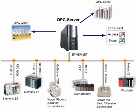
Figure 1. SCADA system based on OPC server architecture
The necessity for communication between production and economic computer systems led to the development of OPC servers. This objective was often met with challenges due to the incompatibilities between custom communication interfaces and the automation hardware and software from different vendors.
The specifications of the OPC refer to a standard COM (Component Object Model) interface for implementation in industrial applications for data acquisition and control.
The specs include a protocol for defining objects, for determining their properties and for standardization of function calls and events. In order to achieve these tasks, the OPC consists of a wide range of data sources.
The data acquisition devices, actuators, communication bus systems and programmable logic controllers (PLC) are included among the input-output devices. The protocols for working with data control systems (DCS) and database applications as well as for access to on-line data, alarm and event control and access to data logs for all these data sources are also included in the specifications [8].
The COM interfaces used for the OPC architecture offer the advantages of a convenient mechanism for extended OPC functionality. The OPC servers created based on their architecture and design allow the data from multiple OPC servers from different vendors running on different nodes on a single object to be accessed by client applications.
Free OPC client interfaces are now provided by all commercially available SCADA systems, process control systems and PC-based controllers for access to any OPC server. Therefore, the main advantage of the OPC interface is the fact that there it is not limited to particular manufacturers, products or hardware.
The technology performs the following tasks: achieving a clear distinction between server and client applications, incorporating product-specific features, easy upgrading to a newer version or replacing with a different product. Due to the independence from the platform, the OPC communication between components running different operating systems and via the Internet can also be achieved.
The OPC standard can only be used with the Windows operating system, since it is based on the DCOM (Distributed Component Object Model) technology; at the same time, the success of OPC was influenced by the DCOM.
The OPC technology has become prevalent in just a few years, due to the rapid acceptance of Windows computers as automation components, while on the other hand, as a result of its increasingly intense use, the OPC standard has to meet new requirements according to the emerging new application fields which determine the general trend towards Web technologies.
The OPC technology used by the application described in section 3 is OPC-UA (Unified Architecture), the next generation of OPC technology, which is a more secure, open, reliable mechanism for transferring information between servers and clients. In contrast to the original OPC, “OPC Classic”, OPC-UA offers such advantages as: more open transports, better security and a more complete information model. OPC-UA is used for moving data between enterprise-type systems and the kinds of controls, monitoring devices and sensors that interact with real world data through a very flexible and adaptable mechanism [8, 9].
OPC-UA is much more complex than previous OPC specifications and is designed to:
- Use cross-platform capable communication instead of Windows DCOM;
- Combine the OPC DA (Data Access), A&E (Alarm &Events), HDA (Historical Data Access) functionality into a single set of services;
- Model complex data structures for collaboration with other standards organizations;
- Be implementable on different platforms, from embedded systems to enterprise systems.
Communication sessions are initiated and data are provided to an OPC-UA client by an OPC-UA server endpoint. In terms of functionality, performance or type of device, there are no standard OPC-UA servers. OPC-UA servers may be represented by devices ranging from small sensors to big computers.
Servers may host a number of data points, ranging from just a couple to thousands of data points. In terms of security, some OPC-UA servers may use mappings with high security and lower performance XML, while others may communicate without security using high performance OPC-UA Binary Encoding. While in the case of some servers the clients can configure the data model views, alarms and events, other servers have no options for configuration.
OPC-UA offers much more flexibility to clients than other networks, with the following benefits: the capability to search out and identify the OPC-UA servers, to determine the method of communication with the OPC-UA server, the capabilities of the OPC-UA servers, and to configure the OPC-UA server to provide specific pieces of data according to their needs. In order to achieve communication with all different types of servers, the OPC-UA clients will generally support many different protocol mappings.

3. Example of OPC-UA Server Based SCADA Application for the Control of an Industrial Process

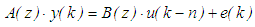
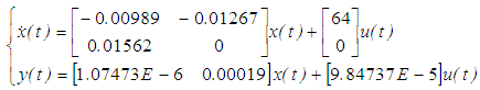
The application presented is achieved in the LabVIEW development environment using Mathscript type Matlab scripts, it uses an OPC-UA type server, TDMS type files and a MySQL type database server. The general architecture of the application is shown in Figure 2.
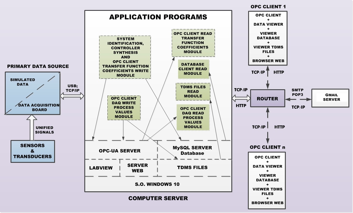
Figure 2. SCADA application architecture
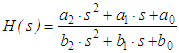
The types of software modules of the experimental model, on the server machine are the following:
- The OPC read-write module; this module will provide intrinsic connection between the data acquired from input modules and the OPC server.
- The MySQL read-write module; this module will achieve MySQL type database query, where obviously data writing and reading are the most used functions.
- The TDMS read-write module; this module will manage data writing and reading in TDMS files, in order to achieve additional cache. These files can be opened in EXCEL, the facilities being thus obvious.
- Interface configuration module for data acquisition channels; this module will achieve the configuration of acquisition channels from various acquisition modules, but in the application presented the process quantities are simulated but maintain a natural similarity to real applications which process data from transducers.
The clients will be programs located on the server computer or on separate computers connected through a router in the same Intranet network. These programs will be Viewer type programs which will access data from the OPC client, from MySQL database or from TDMS files.
Data processing and viewing will be primary, focusing on the data communication itself, in that the data will be acquired by the client uniformly from databases or EXCEL-compatible files, although initially the data sources are heterogeneous (different data acquisition modules, for different protocols) [12, 19].
Most industrial processes (electric, thermal, hydraulic, mechanical, etc.) can be defined around the static operating point by a 2nd order transfer function [14, 15].
Let be the transfer function (on the direct path) of the temperature control process:
(1)
For the identification of the transfer function of the technological process, by using an acquisition board, the step signal applied is acquired and respectively the response (represented in simulated form in Figure 3, (a)).
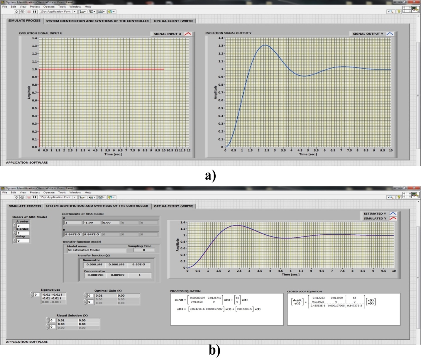
Figure 3. Software interface: a) The step signal applied and the response of the second order system; b) System identification, LQR controller synthesis, state equations and system validation
Using an identification method (ARX model) the coefficients of the transfer function model of the industrial process are obtained [16].
The following equation shows the form of the ARX model.
(2)
Where: u(k) is the system inputs; y(k) is the system outputs; n is the system delay; e(k) is the system disturbance.
A(z) and B(z) are polynomial with respect to the backward shift operator z –1 and defined by the following equations.
(3)
For controller synthesis using LQR (Linear Quadratic Regulator) method is calculated the optimal steady-state feedback gain matrix K that minimizes a linear quadratic cost function [17]:
(4)
Where: u is the input; y is the output; x is the states; t is continuous time; k is discrete time; Q is the state-weighting matrix; R is the input-weighting matrix; N is the cross-weighting matrix between the states and inputs; B is the input matrix; C is the output matrix; D is the direct transmission matrix; I is the identity matrix; X is the solution to the continuous or discrete algebraic Riccati equation.
The optimal gain is:
(5)
The discrete algebraic Riccati equation is defined as:
(6)
The command law is:
(7)
The use of LabVIEW further allows the transfer function coefficients to be determined, a LQR type regulator to be synthesized, a possible state description equations of open circuit, and respectively closed circuit (with regulator) system, as shown in Figure 3, (b).
It is obvious that this procedure is asynchronous and is run on operator request when the operating conditions allow it. The validation of the system and regulator identification is also presented in Figure 3, (b) where it’s seeing that the identified system response is overlaid on the initial response.
The coefficients of ARX model are:
A = [1; -1.99; 0.99], B = [9.847E-5; 9.847E-5].
The numerator and denominator of the transfer function in s are:
Numerator = [0.000198; 0.000198; 9.85E-5],
Denominator = [0.00198; 0.000989; 1].
The optimal gain is: K = [0.01; 0].
The solution of Riccati equation is: R = [0.01 0; 0 0].
A state representation in open loop is given by:
(8)
The OPC-UA Server which supports communication is defined by the software interface in Figure 4, (a), and the software block diagram is presented in Figure 4, (b).
The process quantities defined in the OPC-UA Server as process value PV_1 and PV_2 are transferred synchronously within 1 second and stored in TDMS files with preset time periods (days, weeks, etc.), see Figure 4, (d) and (f).
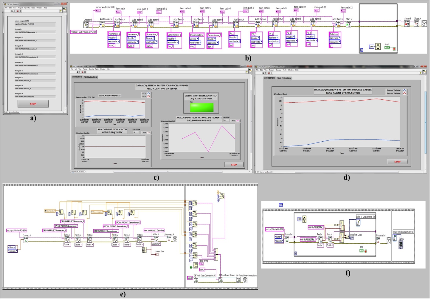
Figure 4. Monitoring system – SCADA integration: (a) OPC-UA Server interface, (b) Software block diagram of the OPC-UA Server (c) Software interface of the process values time evolution, (d), Software interface of the OP UA Client Read, (e) Software block diagram of the OPC-UA Client Write and Database Client Write Module, (f) Software block diagram of the OPC-UA Client Read and Write to TDMS Module
The presented application is modular and can be extended to multiple quantities for an actual industrial process by following the steps implemented in the presentation above. Practically the quantities implemented into SCADA are defined in each software module by groups of interest (quantities accessed synchronously or asynchronously, quantities acquired from the process through acquisition boards from transducers or system description quantities resulting from the process of identification).
The inclusion of several quantities of interest is carried out naturally by following the steps described above.
There will be 8 quantities which will be transferred via the OPC client-server technology, in the presented application (6 digital values and 2 analogue values, namely the process value PV_1 – the temperature reference and PV_2 – the output temperature). The first 6 quantities are the transfer function numerator, respectively denominator coefficients presented in Figure 3, (b).
These quantities will be transferred asynchronously at request and then they will be stored on the MySQL Server (see Figure 5, (a)).
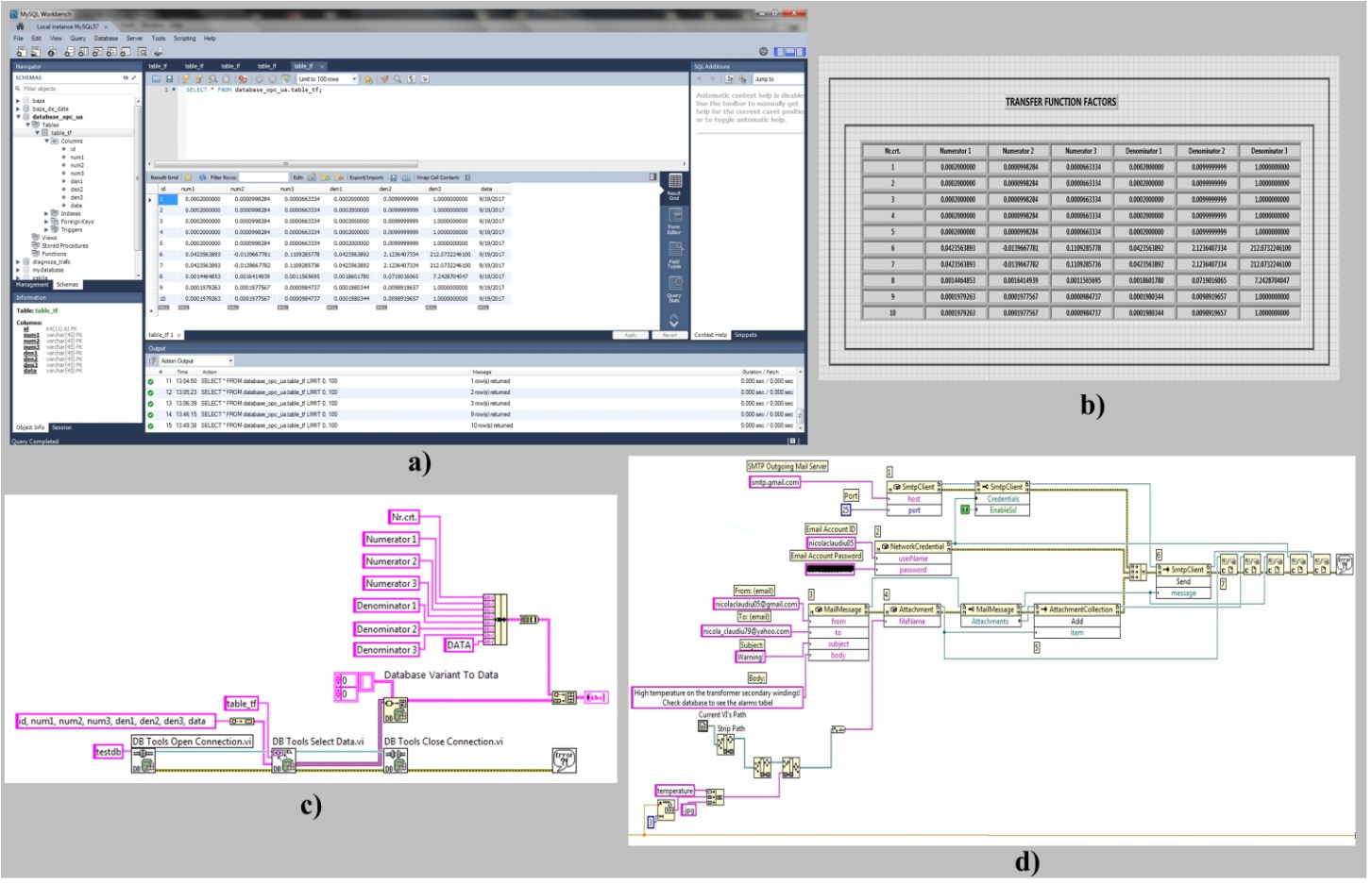
Figure 5. Monitoring system – connection Database and Gmail Server: (a) Database structure, (b) Database selection, (c) Database Client Read Module software block diagram, (d) Send Warning Email Module software block diagram
A DataSources (ODBC) type connection, through which the application program performs the writing and querying of the MySQL Server type database will be used to store the acquired temperatures (PV2) in order to recreate the logging and create automatic reports [18, 19].
Figure 5, (b) shows a sample of the database from which a Word type report can be automatically generated and printed, and Figure 6, (c) shows the block diagram of the Database Client Read Module.
Based on the fact that LabVIEW offers support for Ac-tiveX automation as a server as well as support for ActiveX Containers, and ActiveX Events (ActiveX is an extension of a previous technology called OLE) the application program automatically generates warning emails with alarm reports, to default email addresses when the winding temperature exceeds the alarm threshold.
Figure 5, (d) shows the block diagram of the Send Warning Email Module.
For the exchange of live data with other applications on different computers from Intranet/Internet the presented application program integrates a Web Server through which the application receives queries from a Web Browser and provides the requested data to it for the online display of the process values (See Figure 6, (b)). The structure of the Web Server project developed in LabVIEW is presented in Figure 6, (a).
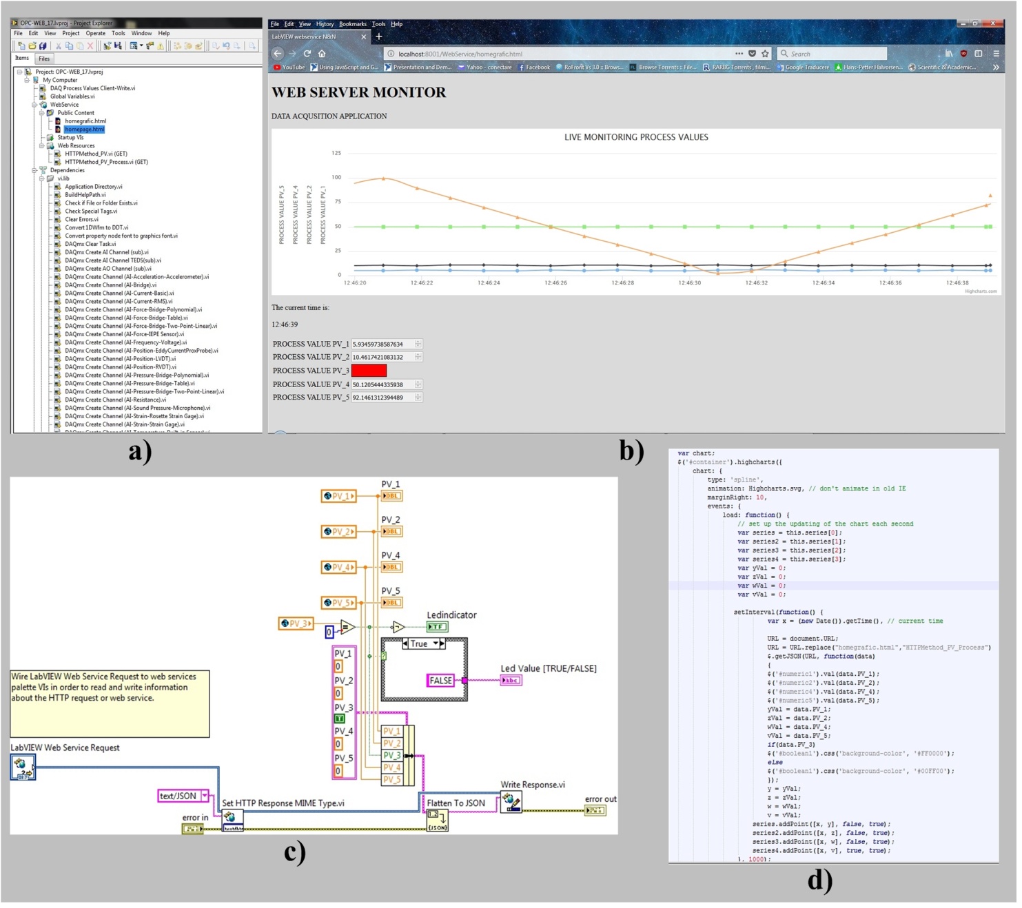
Figure 6. Monitoring system – Intranet/Internet integration: (a) Tree structure of the Web Server project, (b) Process values Web Browser time evolution, (c) LabVIEW WebService request for HTTP Method software block diagram, (d) JSON – HTML implementation
A Web Client can exchange data with a remote LabVIEW stand-alone application over a network through LabVIEW Web Services. A Web Service consists of VI (Virtual In-struments) from LabVIEW and other files running on a server that respond to HTTP (Hypertext Transfer Protocol) requests from clients.
The application program uses URLs and HTTP methods to transmit data directly to controls on the connector pane of Web method VIs, as well as send values as post data using the POST HTTP method.
The LabVIEW Web Service Request is a LabVIEW service which provides communication with the Java Script, and requires the creation, writing and reading of global variables to achieve the data exchange.
The HTML code takes care of most of the visual aspects of the web page and is similar to the front panel which contains indicators and graph charts to display the results.
The Web Service is configured to return the data as JSON (JavaScript Object Notation) which makes it very easy to load as an object in JavaScript. This is done by the JSON. parse function which is available in modern browsers (See Figure 6, (d)). JSON stands for JavaScript Object No-tation and is very similar to LabVIEW clusters. In a JSON object, each piece of data has a key.
In a LabVIEW cluster, each element can have a name, so that you can use the unbundle/bundle by name functions to easily modify clusters. We will be using a function that converts LabVIEW clusters into JSON objects. The function will turn the name of each cluster’s element into a JSON key [20].
The block diagram of the communication modules between the application program and the Web Server integrated into LabVIEW is show in Figure 6, (c).

4. Conclusions

This article summarizes the SCADA systems and the principles of OPC client-server communication. Hence an application was achieved and presented for monitoring a quasi-general industrial process defined by a 2nd order transfer function, for identifying the transfer function and managing the client-server communication of the quantities of interest by online viewing and creating a record using TDMS files and a MySQL database server.
The implemented main software modules achieve the following: writing of the filtered data in the OPC-UA, MySQL, Web servers, showing the instant evolution of the acquired values, achieving automatic reports, storing the evolution in a database, managing the alarms by automatically sending to default email addresses, achieving integration into SCADA and allowing the display of data on the Intranet/Internet through via a Web Server which is embedded in the application.
The issue of data communications in industrial environments is not abstract, but arises practically in industrial and monitoring applications, and can become a separate issue, but it can only be studied on condition that minimal software modules are provided for data communication and management from an actual application.
We consider that by achieving such an experimental model like the one described above, but especially by means of the experiments conducted on it, the main benefit will consist in the increase of the amount of knowledge on this topic and a significant facilitation in achieving future complex monitoring applications for systems with a relatively large volume of data and for heterogeneous data acquisition systems.

ACKNOWLEDGEMENTS

The paper was developed with funds from the Ministry of Education and Scientific Research as part of the NUCLEU Program: PN 16 15 02 06.

References

[1]  M. Nicola, D. Sacerdoțianu, M. Duță, D. Popa, Sisteme SCADA pentru monitorizarea echipamentelor electrice, Ed. Electra (ICPE), Romania: Bucharest, 2011.
[2]  H. Geng, SCADA fundamentals and applications in the IoT. 1st Edition, Wiley Telecom, 2017.
[3]  S. A. Boyer, SCADA: Supervisory. Control and Data. Acquisition. 3rd Edition, ISA The Instrumentation, Systems, and Automation Society, 2004.
[4]  D. Bailey, E. Wright, Practical SCADA for Industry, IDC Technologies, 2003.
[5]  Nicola, M., Nicola, C. I., Sacerdoțianu, and D., Duță, M., 2017, SCADA systems architecture based on OPC Servers and applications for industrial process control, Proc., 23rd Edition International Conference on Hydraulics and Pneumatics (HERVEX), Băile Govora, Romania, 222–232.
[6]  Kumar, N., and Kumar, U., 2012, Simulation of Virtual SCADA system using LabVIEW, Proc., IEEE 5th India International Conference on Power Electronics (IICPE), Delhi, India, 1–5.
[7]  J. Rinaldi. OPC-UA – Unified Architecture: The everyman’s guide to the most important information technology in industrial automation, CreateSpace Independent Publishing Platform, USA: South Carolina, 2016.
[8]  Qing, L. and Yongsheng, Q., 2015, Development of OPC server in a remote industrial control system, Proc., 12th IEEE International Conference on Electronic Measurement & Instruments (ICEMI), Qingdao, China, 552–557.
[9]  Guo, H., and Zhi, D., 2011, Design of several OPC servers communication system, Proc., International Conference on Electric Information and Control Engineering, Wuhan, China, 317–319.
[10]  Dongjiang, L., and Ruiqi, S., 2011, Implement of communication between configuration software and OPC server based on Modbus/TCP, Proc., IEEE 10th International Conference on Electronic Measurement & Instruments, Chengdu, China, 218–221.
[11]  Nunoo, S., and Ofei, A. K., 2010, Distribution automation (DA) using supervisory control and data acquisition (SCADA) with advanced metering infrastructure (AMI), Proc., IEEE Conference on Innovative Technologies for an Efficient and Reliable Electricity Supply (CITRES), Waltham, MA, USA, 454–458.
[12]  Patrascoiu, N., Ioana, C. R., and Barbu, C., 2017, Virtual instrumentation for Data Acquisition and remote control, Proc., 18th International Carpathian Control Conference (ICCC), Sinaia, Romania, 99–102.
[13]  Gîrbea, A., Demeter, R., and Sisak, F., 2011, Automatic address space generation for an OPC-UA server of a flexible manufacturing system, Proc., 6th IEEE International Symposium on Applied Computational Intelligence and Informatics (SACI), Timisoara, Romania, 483–488.
[14]  D. Popescu, A. Gharbi, D. Stefanoiu, P. Borne, Process Control Design for Industrial Applications, Ed. ISTE Ltd Wiley, UK: London, 2017.
[15]  W. Zhang, Quantitative Process Control Theory, CRC Press, USA, 2017.
[16]  J. Kon, and Y. Yamashita, 2010, Model predictive control based on ARX models, Proc., Control Automation and Systems (ICCAS), Gyeonggi-do, South Korea, 448–452.
[17]  A. H. Bajodah, and H. Mibar, 2016, Partial eigenstructure assignment on LQR control for continuous LTI systems, Proc., 4th International Conference on Control Engineering & Information Technology (CEIT), Hammamet, Tunisia, 1–6.
[18]  R. Bitter, T. Mohiuddin, M. Nawrocki. LabvVIEW: Advanced programming techniques, Second Edition. CRC Press, USA, 2006.
[19]  J. Jovitha. Virtual Instrumentation using LabVIEW. PHI Learning, India, 2010.
[20]  S. A. Gabarro. Web Application Design and Implementation: Apache 2, PHP5, MySQL, JavaScript, and Linux/UNIX. Wiley-IEEE Press, 2007.