-
Paper Information
- Paper Submission
-
Journal Information
- About This Journal
- Editorial Board
- Current Issue
- Archive
- Author Guidelines
- Contact Us
International Journal of Control Science and Engineering
p-ISSN: 2168-4952 e-ISSN: 2168-4960
2018; 8(1): 1-12
doi:10.5923/j.control.20180801.01

Mathematical Modeling and Simulation of a Twin-Engine Aircraft Fuel System Using MATLAB-Simulink
 Abstract
 Reference
 Full-Text PDF
 Full-text HTML
Ishola A. Afiz1, Rachel Cunliffe1, Talib Alukaidey2
1Aerospace Engineering Department, University of Hertfordshire, United Kingdom
2Electrical and Electronics Department, University of Hertfordshire, United Kingdom
Correspondence to: Ishola A. Afiz, Aerospace Engineering Department, University of Hertfordshire, United Kingdom.
| Email: |  |
Copyright © 2018 Scientific & Academic Publishing. All Rights Reserved.
This work is licensed under the Creative Commons Attribution International License (CC BY).
http://creativecommons.org/licenses/by/4.0/

Engineering applications of control systems has been in the forefront of technological advancement and development of mechanically automated machines as well as complex interconnected systems. In the aerospace industry, the adoption and integration of control system for fuel system of an aircraft which is a complex series of interconnected devices such as pumps, valves, injectors, switches, metering and monitoring devices that are required to supply fuel in proportion for effective and efficient engine’s throughput. This analysis is involved with fuel depletion rate of a model flight cycle considering all the aircraft static and dynamic variables. A theoretical model is sampled and tuned with a Proportional Integral and Derivative (PID) controller to interface a light-wing two-engine aircraft fuel system in order to control the fuel flow, monitor and optimize efficiency within the fuel system. A mathematical model is developed for the fuel system and simulated on MATLAB-Simulink software. The fuel consumption profile is plotted and the extracted results validated with similar analogous plots by Robert and Vladmir.
Keywords: Control System, Aircraft Fuel System, Mathematical Modeling, PID Controller, MATLAB-Simulink
Cite this paper: Ishola A. Afiz, Rachel Cunliffe, Talib Alukaidey, Mathematical Modeling and Simulation of a Twin-Engine Aircraft Fuel System Using MATLAB-Simulink, International Journal of Control Science and Engineering, Vol. 8 No. 1, 2018, pp. 1-12. doi: 10.5923/j.control.20180801.01.
Article Outline
1. Introduction
- The rapid advancement in modern technology is a critical factor for development and also of economic importance. The capacity to develop and adopt various techniques or strategies which improves the welfare and operational requirements of an aircraft has been a major challenge confronting the aerospace industry. Aerospace organizations are in a continuous state of improvement as advanced and cutting-edge technologies are employed to control, operate, monitor and optimize aircraft performance. The determination to excel in a competitive market is the key to major research and development of improving the efficiency of systems and part components.The aircraft is a complex structure designed on many automated systems that are required to effectively carry out the desired functions, [1]. These technologies, however, adopted are referred to as flight control systems and are integrated in order to maximize performance and optimize efficiency of the aircraft. An aircraft flight control system ensures the safety of passengers and crew members alike if properly designed and incorporated. It is important to know that a major advantage of aircraft control systems reduce overload on pilots with regards to decision making which may lead to flight handling errors, [2]. Most modern aircraft have been improved such that most mechanical and electronic systems that operate different parts of the aircraft are automated and computer controlled. Pilots can control and monitor the entire systems and sub-systems of the aircraft within the cockpit. Control surfaces responsible for aircraft manoeuvers are digitally controlled as well as the auto-pilot which is a common feature in most modern commercial aircraft are the possibilities of control systems engineering, [3, 4]. Aircraft fuel system is a significant feature of an aircraft design because it is responsible for the supply of fuel to the aircraft engines in order to produce propulsion which enables aircraft operations. A requirement for both commercial and military aircraft is to carry aboard fuel supply that will meet the operating range of requirements, [3]. The aircraft engine cannot function without fuel being supplied to its combustion chambers in required proportion, therefore, the fuel system is also designed to control the amount of fuel required by the engine at a particular incidence to produce enough power for the aircraft to function as required. Application of control theory to an aircraft fuel system has a major impact on the fuel system performance and efficiency. In order to optimize the fuel system performance, a control system is incorporated which controls the fuel system components such as pumps, valves, vents, switches and sub-systems, [4]. Generally, most control operations are carried out by means of a control logic. A control logic is a schematic program designed to control a system by interconnecting the system devices in form of inputs and outputs.
1.1. Aims and Objectives
- This research is aimed at the control of an aircraft fuel system by means of adopting control systems engineering principles and methods. To model a low-wing twin-engine light aircraft fuel system model such as the Boeing 737-800. A mathematical representation of the model is developed and simulated in MATLAB-Simulink software to analyse the fuel consumption rate and a tuned system with a PID controller. The objectives are to understand the application of control systems in managing an aircraft fuel system, acquire the technical knowledge of controls and convectional fuel system of an aircraft, gather information on parts and components of aircraft fuel system as well as the functionality of the entire system operations also to develop the principles of mathematical modelling of flow systems and process control.
2. Technical Background
- Aircraft fuel system is developed in closed loop for a feedback control mechanism. Nicholas Minorsky, 1922, developed nonlinear elements in a closed-loop system which was used for the automated process of steering ships, [6]. Minorskys’ theory is the method of control which in modern control engineering is known as the PID (Proportional + Integral + Derivative), [7]. The process of control was basically to switch on or off of devices such as valves, pumps and motors, directly or with the use of relays. Though, mechanical controls were mainly adopted for speed and variations in inputs for navigation purposes but towards the later part of the decade, the knowledge of improving the controls became obtainable by separating measurement and actuation by a unit and the signal generated by the measuring device can be amplified, [7]. However, many control systems that depend on the adjustment of the feedback signals obtained from the measuring devices have been in use before the 1930s. Modern control systems which has wide spread of applications became pronounced in the early 1940s with the use of mathematical and analytical methods which was used to improve systems. Most modern control systems have installed digital controllers which are also referred to as compensators. A computer-controlled system is characterized by discrete-time signals and continuous-time signals. The continuous-time signal is the output process and it is transformed into digital form with the aid of analog-to-digital converter, [8]. The transformation is achieved at sampling times where the computer reads the transformed signal in form of a sequence of numbers then generates a new sequence of numbers. A digital-to-analog converter transforms the new sequence of numbers into analog signal. A real-time clock programmed on the computer performs the synchronization of this process and this is achieved by keeping the control signal constant between the conversions, [8]. Further design conceptualization as reviewed by [4] presents comparison between two fuel system and analysis made using Design Structure Matrix (DSM). As illustrated in figure 1 first fuel system is incorporated with fuel transfer pump while the second system adopts the use of siphon. The two tanks in the first model are pressurized to prevent cavitation in the pump but the siphon model transfer fuel by pressure difference in order to supply the engine feed tank.
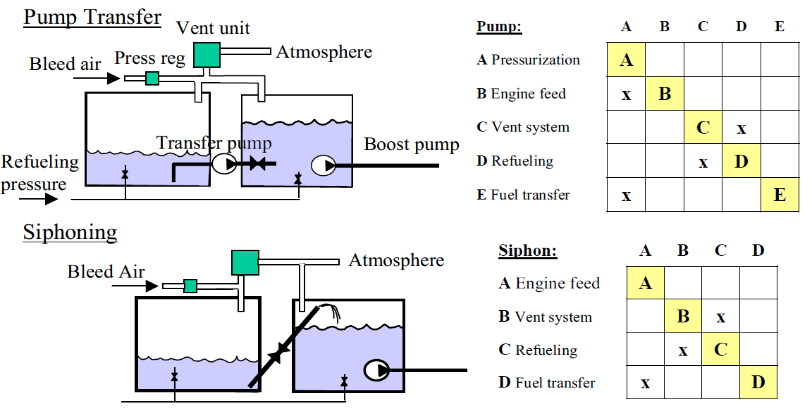 | Figure 1. Design principles of fuel transfer by pump and siphon using DSM, [4] |
2.1. Design Approach and Principles
- In the quest to design an aircraft fuel system which is a complex algorithm of logic positioning, feeding and control, it is necessary to divide into subsystems. The most suitable task for any system to be implemented is to produce a model simple and suitable enough to represent the actual system. The design approach can me descriptive or prescriptive using morphological approach or mathematical approach to analyse the system. As stated by [4], a descriptive process is the sequence of design tasks which occur in practice and often focus on concepts to be analysed and further refined. Fuel system design of early aircraft developed problems due to early stage of research and implementation methods but aircraft modern aircraft are equipped with sophisticated models of integrated fuel systems. The main operational modes in design principles of modern aircraft includes Fuel pressurization, Engine feed, Fuel transfer, Ground /Air refuelling, Vent system, Fuel jettison, Defueling and Fuel flow as heat sink.
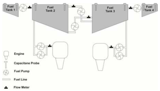 | Figure 2. Block model of aircraft fuel system as developed by Robert and Vladmir, [25] |
2.2. Aircraft Fuel System Model Specifications
- This research focus on the aircraft fuel system of low-wing, twin-engine light aircraft. A typical example of such aircraft is Boeing 737-800 designed to have a dual fuel feed system. A default design principle is that the right tanks feeds the right engine while the left tanks feeds the left engine. A cross-feed fuel line links the right fuel system to the left fuels system. A central tank found at the middle of the fuselage serves as a collector tank while the tanks at the tail area are trim tanks. The cockpit controls are mostly digital control and the fuel system and most subsystems within the aircraft can be monitored in the cockpit display. An actual 737-800 fuel system schematic is displayed in figure 3 showing the fuel connections, valves positioning and engine feed.
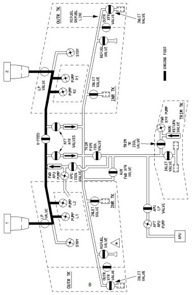 | Figure 3. Schematic diagram of fuel system for Boeing 737-800, [23] |
2.3. Synopsis of an Aircraft Fuel System
- Aircraft fuel system is an important part of the aircraft design; it also plays a major role in the operation and certification of the aircraft. Both military and civil aircraft have installed fuel system within the structure that enable a suitable flying range, [3]. Aircraft fuel system greatly differ between aircraft based on aircraft design, [13]. The fuel system of an aircraft is a series of interconnections of various parts and devices with appreciable complexity. The common types of aircraft are equipped with one, two, or four engines depending on size, speed, and weight. The major function of the fuel system is to supply fuel to the engines at any flight level, condition and manoeuver.
 | Figure 4. Fuel system from an aircraft view, [3] |
3. Fuel System Modelling
- The process of design is a highly technical procedure with regard to fuel supply and control monitoring of the fuel system. It is requirement to consider all technical difficulties that may arise from design, manufacturing and commissioning of the fuel system devices and processes. Depending on the type of aircraft and the operating range, various designs of the fuel system are considered. However, the critical requirement of the fuel system is to store and deliver fuel to the engine in adequate quantity and pressure without failure, [22]. The developed model of the fuel system is a simplified model of the actual fuel system for Boeing 737-800 carrier aircraft. An important aspect is to first create a physical model and then develop the mathematical model of the fuel system. The physical model is carved for analysis purpose only which can be related, improved or implemented for the actual system. In order to achieve a physical model, the most important elements and subsystem are extracted from the actual design. Fault tolerant design of fuel system has been included in the analysis by adopting fuel system independency at wings, cross-feed system in case of pump failure at one wing, fuel jettison for weight reduction in emergency landing and fuel transfer between wing tanks for aircraft stability and aerodynamics. An important detail to note is that the fuel system design is symmetric, therefore, each side if the fuselage is equipped with the same devices and parts.
3.1. Mathematical Modeling of Aircraft Fuel Pump System
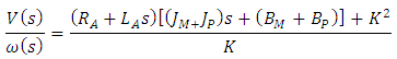
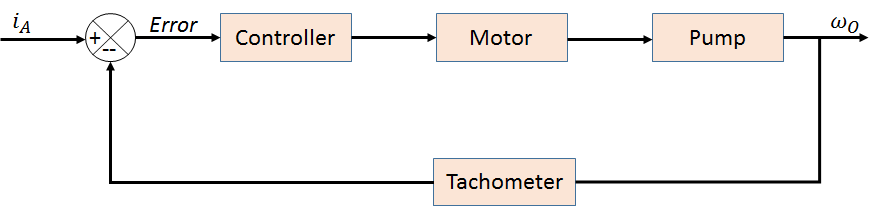
- Control system adopts the mathematical models of system to analyse and optimize the variables. The control system functions on the input and output theory where the output is a desired variable and the input is the introduced variable. The transformation of an input to output is described as a function but the ratio of an output to an input is referred to as the transfer function of the system. An open-loop system has no feedback meaning there is no metering device that measures the output of the system. A cycle of an interconnected system is classified a closed-loop or feedback systems. The fuel pumping process is an example of a subsystem with very important characteristics in the operational requirement of the fuel system. The pump is a device that converts mechanical energy into fluid energy. It is used to transport, lift and increase or reduce pressure of fluid flow. There are different types and classifications of pumps but most modern aircraft use centrifugal pumps which are fitted inside the fuel tanks, variable displacement pumps and vane pumps which are engine powered pumps. The pump system model analysis in this section is concerned with basic mathematical model principle. An electric powered pump is a link between subsystems with voltage input which eventually produce the rotational output.In order to model the pump process of the fuel system, an electrical circuit is designed to pass electric current to the electric motor. The motor transform electrical energy into rotational energy by means of electromagnetic induction. The rotational output of the motor is coupled with the shaft of the pump as input and the output speed is measured to provide information on the speed of the pump. Pump speed is required to provide sufficient flow as required by the main system.
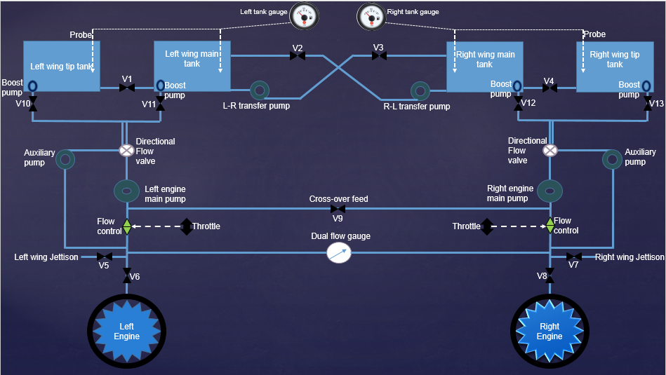 | Figure 5. Simplified network model of the aircraft fuel system |
3.1.1. Mathematical Model of Pump System
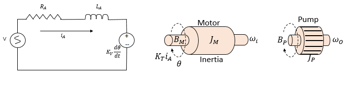
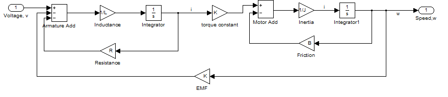
- The pump system as illustrated in figure 6 will require a feedback system to measure the output speed of the shaft. A tachometer is an instrument normally used to take readings from a rotating shaft. The block diagram of the model is shown in figure 7.The mathematical model of the pump system is analysed using the variables as defined as follows:V, input voltage, (volts)
 , armature resistance, (ohms)
 , armature inductance, (Henry)
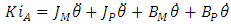
 , armature current, (amps)K, electromotive force, (NmAmp-1)
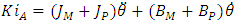
  , angular speed of the shaft, (rads-1)JM, moment of inertia of motor, (Kgm2s-2)JP, moment of inertia of pump, (Kgm2s-2)BM, friction of the motor, (Nms)BP, friction of the pump, (Nms)
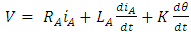 | (1) |
 | (2) |
 | (3) |
 therefore,
  Converting the equations to Laplace form and rearranging equation (3), gives:
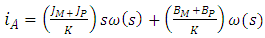 | (4) |
 into the Laplace transform of equation (1) gives:
 | (5) |
 | (6) |
 | (7) |
 | (8) |
 | Figure 6. Pump system interconnection |
 | Figure 7. Block diagram model fuel pump system |
3.1.2. Aircraft Fuel Pump Modeling with MATLAB-Simulink
- The pump system model on MATLAB is a way of analysing the process by simulation. The links are connected as the block diagram shown in figure 7 and values are assigned to the variables. An assumption is that the motor is DC powered, therefore, the system gain (K) values are constant.The block diagram above is modelled into a subsystem by enclosing all variables into a block. A PID controller is connected to the system as shown in figure 8 to tune the response for a suitable system characteristics. This system is monitored using the feedback process to read output information.A signal builder models an input voltage into the system with the input profile diagram while the PID controls the output variable of the system characteristics. The response plot of the block and tuned system are shown in figure 10.
 | Figure 8. Block diagram of pump system on Simulink |
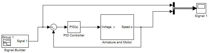 | Figure 9. PID controller attached to the pump system |
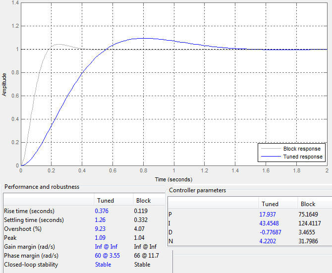 | Figure 10. Response plot of the fuel pump system |
3.2. Mathematical Modeling of Aircraft Fuel System Flow Rate
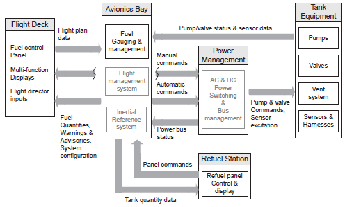
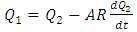
- A feedback system provides a reliable and accurate output variable but it is also accustomed with defects. This is because the data about performance is measured and the data is used to improve the system performance. Generally, systems are characterized with either positive feedback or negative feedback. The positive feedback are known as feed-forward which add-up to system output. The block diagram is a schematic representation of the fuel flow which illustrates the flow function of the fuel system. The system is governed by assumptions and variables in order to simplify the model and analyse the system dynamics. A generalized flow system modelling is shown in figure 11.The representation above gives the implication of a feedback which measure the output variable of a system. A clear observation is that the entire system is an open-loop but each subsystem is a closed-loop. The tank is installed with probes or sensors which measure the level of fuel in the tank. The sensors feeds the control unit which is indicated by a level gauge in the cockpit. The pilot can view the level of fuel in the tank and can make a decision either to refuel or proceed to airborne. A Pump increase the flow of the fuel in the system as well as the pressure, therefore, a flow meter is installed to monitor the flow rate of fuel in the system in order to checkmate that the fuel is flowing at specified volume per time. The throttle input is a variable source that has effect on the engine output. An integrator is included so as to complement the variability of fuel flow required by the engine based on the throttle control. A throttle meter provide information of the fuel consumption rate per travel distance at a particular instance in time. The assumptions adopted for this model are that the four tanks are represented by one tank for a simplified flow dynamics, the fuel pump rate is equal to the fuel consumption rate of the engine and he throttle input is steady over time. The transfer function of the flow system in figure 11 can be expressed in words as follows.A simple theoretical model of fuel flow dynamics as described in figure 12 is an outflow-to-outflow process which replicates the flow process as seen in the aircraft fuel system. The tanks are refueled at the initial condition and gradually depletes during operation of the aircraft. The model feature an outflow (Q1) from the tank of dimensional height (h) and cross-sectional area (A). The pump exerts pressure to the fuel which produces and another outflow (Q2) of greater pressure. A restrictor (R) is situated at the outflow (Q2) to regulate the volume discharge to the engine. The transfer function of the system in mathematical expressions is analysed as follows.
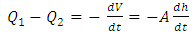 | (9) |
 Substituting Q2 into equation 5, gives,
 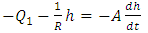 | (10) |
 | (11) |
 | (12) |
 | Figure 11. Block schematic of a generalized flow system |
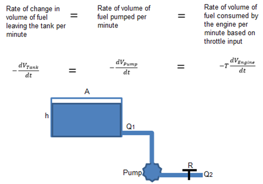 | Figure 12. Flow model (outflow-to-outflow) |
3.3. Simulation Configuration and Running
- Modern modeling technique for fuel system is achieved with the aid of computer software. MATLAB software is a common mathematical tool used for technical and scientific analysis. It is adopted to solve complex equations, arithmetic and mathematical problems. A unique advantage of MATLAB is that it can simulate models of required analysis and its results are mostly accurate. Accurate results can only be achieved if the models are provided with the correct input variables and also the model interpretation on MATLAB is performed properly. MATLAB-Simulink tool is a sub-module within the MATLAB software. Simulink has basic and advanced tools for control system modelling and simulation. A discrete approach is used for the analysis of the fuel system model. As earlier stated, attention is focused on the fuel consumption profile of the aircraft. The process involve simulation of the aircraft fuel system model as proposed in figure 5 using four tanks for the modeling. A simplified model is developed for system by combining all four tanks fuel capacity together. In order to carry out the fuel system model, the assigned variables are provided for the maximum fuel weight and the vehicle weight. A similar model of this system is experimented on MATLAB-Simulink, however a modified model of the system is analysed for this research.The signal input is framed on the Simulink module and programmed with a velocity profile as displayed in figure 14. This is compared with a feedback from the output source and the integrator. The aircraft is programmed to fly a time range of 15,000 seconds (4 hours 17 minutes) following the velocity profile as illustrated in the signal input. The fuel mass aboard is specified for 20,000kg and the precise weight of an empty Boeing 737-800 is 91300lb (41,412.9kg), [24].
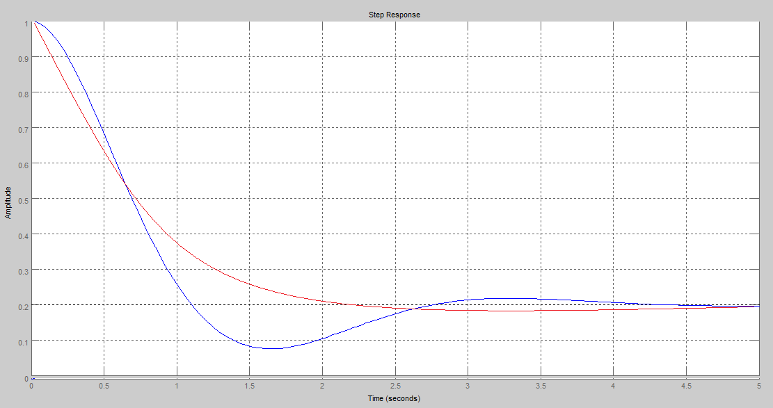 | Figure 13. Step response of fuel outflow model, tuned (red) and block (blue) |
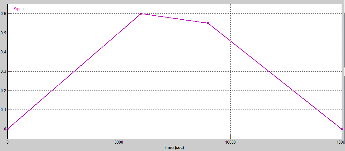 | Figure 14. Signal input of the velocity profile using the signal builder on Simulink |
 | Figure 15. Aircraft fuel system model and configuration on MATLAB-Simulink |
4. Simulation Results
- A PID controller is included in the system to tune the system response for a suitable profile which is fed to the aircraft engine thrust. The drag force of the aircraft is measured for 125 kg/kN while the engine thrust is 343 kg/kN. The fuel system simulation is performed for the fuel consumption analysis.Comparison with the signal input shows that the output follow the same pattern of profile. A noticeable difference is the steep profile on the left side and this is due to the engine thrust which the PID has tuned for a suitable system response. PID tuning play a major role in the performance of the fuel system because it increases system rise-time, decreases overshoot and also eliminates the steady state error. The plot of the fuel consumption profile indicates that the flow system is nonlinear. The time range is suitable as assigned because the aircraft did not run out of fuel while in operation. Also, the depletion rate was steady for almost a third of the entire flight duration. This method can enhance the design for optimal performance of the aircraft fuel system.
4.1. Validation of Results
- As proposed by Robert and Vladmir, [25], the fuel system modeling of a small aircraft composed of four fuel tanks with four valves designed with anti-fire function. There are four main fuel pumps with two backup pumps and also two other pumps for emergency purpose. A two member crew is required with minimal load aboard the aircraft and delivery of fuel is automatically controlled while manual control of the pumps is performed only in the events of emergency. The wing tip fuel tanks and main tanks has a capacity of 350kg and 525kg respectively making a total weight of 1,750kg. Sensors are used in the fuel tanks to monitor the fuel consumption while the fuel system will include connecting valves, shut-off valves and fire prevention valves. The simulation result of the experiment is compared with the theoretical flow system model and fuel system model as proposed by Robert and Vladmir, [25] in order to validate the system profile. The fuel depletion profile of the three models are shown in figure 17. An observation is that the fuel in the tanks drops at a rate as described by the negative exponential curve. The velocity profile signals can also affect the depletion profile of fuel in the tanks. The comparison shown below give a clear indication of the fuel flow and this can be used to design or optimize and aircraft performance.
4.2. Complexity of Aircraft Fuel System Modelling
- The expressions in previous section are basic simplified models of fuel flow control system. The issue with the expressions is that they cannot produce valid models to describe an actual flow process of the system. A complex flow system will require more advanced and sophisticated modeling technique which will be an acceptable mimic of the actual system. The use of equations to describe the system attribute will be an excessive show of mathematical expressions which will be difficult to interpret and implement. The use of computer model such as MATLAB-Simulink provide suitable means of expressing the fuel system. It enables the complexity be managed and modifications can be made to improve the system performance while the data extracted from the simulation can be validated.More often, models of fuel delivery are simulated which allows the view of the functional characteristics of the fuel system. Modeling small commercial aircraft is quite easy due to the simple models used and also the few number of tanks and other fuel system elements. In the advent of fuel depletion which has significant effect on the CG margin, it is important to focus attention on the fuel system operation which can affect the stability of the aircraft. This can make the fuel system modeling more complex when such criteria is considered.
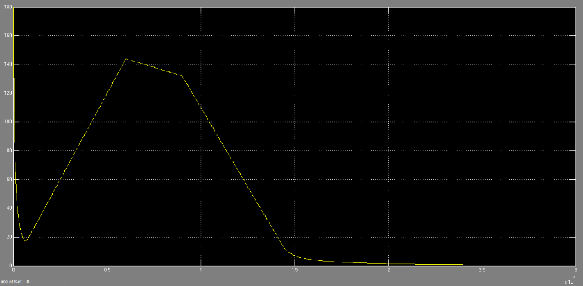 | Figure 16. Output signal of the aircraft velocity profile |
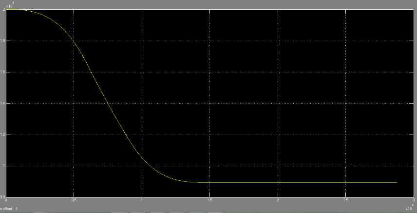 | Figure 17. Fuel consumption profile of the aircraft (Volume/Time) |
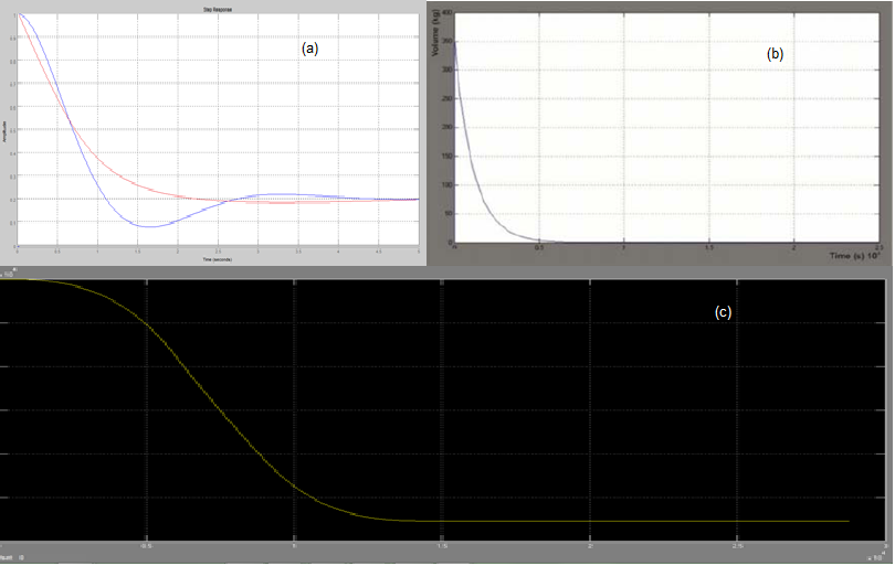 | Figure 18. Comparison of fuel depletion profile (V-t) of an aircraft fuel system (a) Theoretical model, (b) Model of Robert and Vladmir, [25] and (c) Developed model tuned with a PID |
5. Future Development
- Fuel system modeling involves series of interconnection between various elements of the fuel system. However, a design objective can be a resource to manipulate the operational qualities in little proportion. A more detailed approach is required using the four tanks and analysis can be carried out on fuel depletion rate between the wing-tip tanks and the wing main tanks. This will enable a more sophisticated approach in improving one of the major properties in the design of the fuel system which is to optimize the aircraft aerodynamics. This is due to the concept of consuming the fuel at the tip tanks which are outboard before using that of the main tanks inboard the wings. This greatly improves stability and prevent unprecedented banking of the aircraft.
ACKNOWLEDGEMENTS
- I sincerely appreciate the support of the University of Hertfordshire, Aerospace Engineering Department, for permitting the use of control laboratories in the course of developing this research. I also appreciate my supervisors, Dr Rachel Cunliffe and Professor Talib Alukaidey for their immense contribution towards this extensive development of mathematical models and MATLAB modelling. Lastly, I appreciate this journal for publishing this scientific research document for the contribution to science and technology.