-
Paper Information
- Paper Submission
-
Journal Information
- About This Journal
- Editorial Board
- Current Issue
- Archive
- Author Guidelines
- Contact Us
International Journal of Control Science and Engineering
p-ISSN: 2168-4952 e-ISSN: 2168-4960
2016; 6(2): 49-57
doi:10.5923/j.control.20160602.03

A Design Method of Reference Model for near Time Optimal Model-Following Servo Controller: A Case Study for Multi-Zone Heating System with Input Saturation
 Abstract
 Reference
 Full-Text PDF
 Full-text HTML
Kazuhiro Mimura1, Tetsuo Shiotsuki2
1System R&D Department, KELK Ltd., Kanagawa, Japan
2Department of Robotics and Mechatronics, Tokyo Denki University, Tokyo, Japan
Correspondence to: Tetsuo Shiotsuki, Department of Robotics and Mechatronics, Tokyo Denki University, Tokyo, Japan.
| Email: |  |
Copyright © 2016 Scientific & Academic Publishing. All Rights Reserved.
This work is licensed under the Creative Commons Attribution International License (CC BY).
http://creativecommons.org/licenses/by/4.0/

This paper proposes a design method of reference model for model-following servo (MFS) control which overcomes the difficulty of control input saturation. One typical application of MFS control is heating and/or cooling plate control of semiconductor wafer fabrication. The control object is inherently MIMO (Multi Input Multi Output) system with interaction and input saturation and requires both temperature uniformity and faster response. MFS control is a well-known effective technique for tracking control of MIMO system with interaction and disturbances. However input saturation obstacles the accomplishment of the control requirements In order to overcome this difficulty we introduce a new design method of reference model and input signal based on master-slave step response tests and near time optimal simulations. Experimental results indicate the effectiveness of the proposed reference model design method which realizes both faster response and better uniformity.
Keywords: Reference Model, Model-Following Servo Control, Optimal Control, Time Optimal Control
Cite this paper: Kazuhiro Mimura, Tetsuo Shiotsuki, A Design Method of Reference Model for near Time Optimal Model-Following Servo Controller: A Case Study for Multi-Zone Heating System with Input Saturation, International Journal of Control Science and Engineering, Vol. 6 No. 2, 2016, pp. 49-57. doi: 10.5923/j.control.20160602.03.
Article Outline
1. Introduction
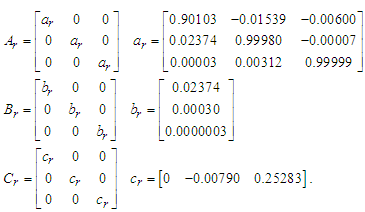
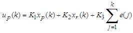
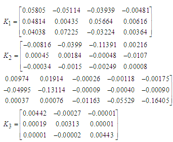
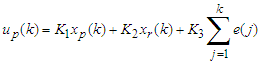
- Many of the industrial processes are MIMO system with interaction. One typical application is heating and/or cooling plate for semiconductor wafer fabrication. The plate usually consists of multiple zones and each zone temperature should be controlled accurately. The requirements to the temperature control are(1) The temperature should reach the set-point variable (SV) as quick as possible to realize high throughput. (2) Temperature uniformity or temperature gradient is kept constant both transient and steady state response.In spite of these requirements, temperature control is very challenging due to the interactions between the neighbour zones and many studies have been conducted [1-3]. Model-following servo (MFS) control [4, 5] is suitable for the MIMO system with interaction because, 1) it has the advantage of the optimal control such as stability and robustness, 2) we need not consider decoupling design explicitly. As shown in Figure 1, the MFS control consists of plant, reference model, integrator, state feedback gain K1 from the plant, feedforward gain K2 from the reference model, and gain K3 for the integrator. A low order system that has a desired dynamics is usually chosen as a reference model. The process variable, yp, follows the step response of the reference model, yr.
 | Figure 1. The structure of the model following servo control |
2. Disadvantage of Conventional MFS Control
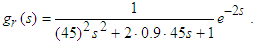
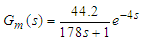
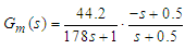
- Figure 2 illustrates test plant for the temperature control of an aluminium plate which size is 400 x 150 x t4. Three Peltier modules for heating and cooling are allocated unsymmetrically in a longitudinal direction of the plate. Plate temperatures are measured by three Type-K thermocouples. Each of them is allocated near the Peltier module. Zone number is assigned as zone 1, 2, and 3 from the left.We designed conventional MFS controller for this test plant. In order to obtain a plant model we conducted step response experiment for one zone at a time. Each response data is approximated by a first order plus dead time model. Whole test plant model is expressed by transfer function matrix as shown in eq. (1).
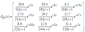 | (1) |
 | (2) |
 | (3) |
 | (4) |
 | (5) |
 | (6) |
 | (7) |
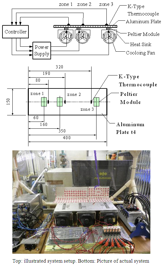 | Figure 2. Test plant for the temperature control of aluminium plate |
 | (8) |
 | (9) |
 | (10) |
 | (11) |
 | (12) |
 | (13) |
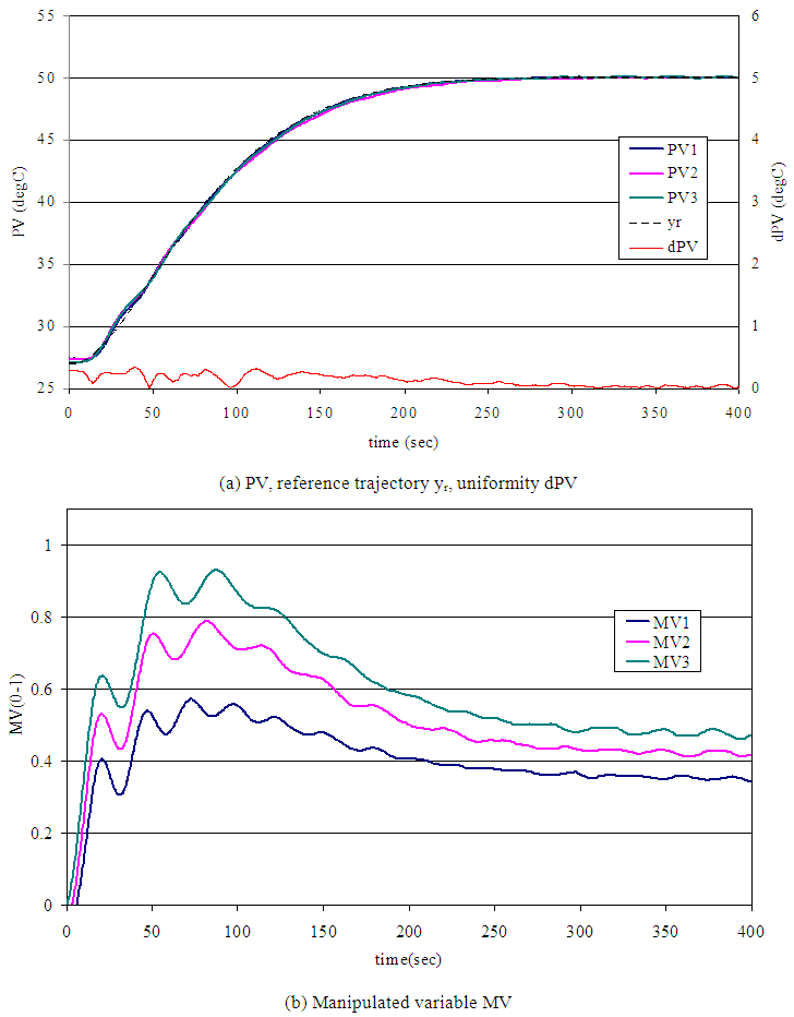 | Figure 3. Experimental result of set-point response. Reference model parameter ω0=1/45 rad/sec, ζ=0.9 |
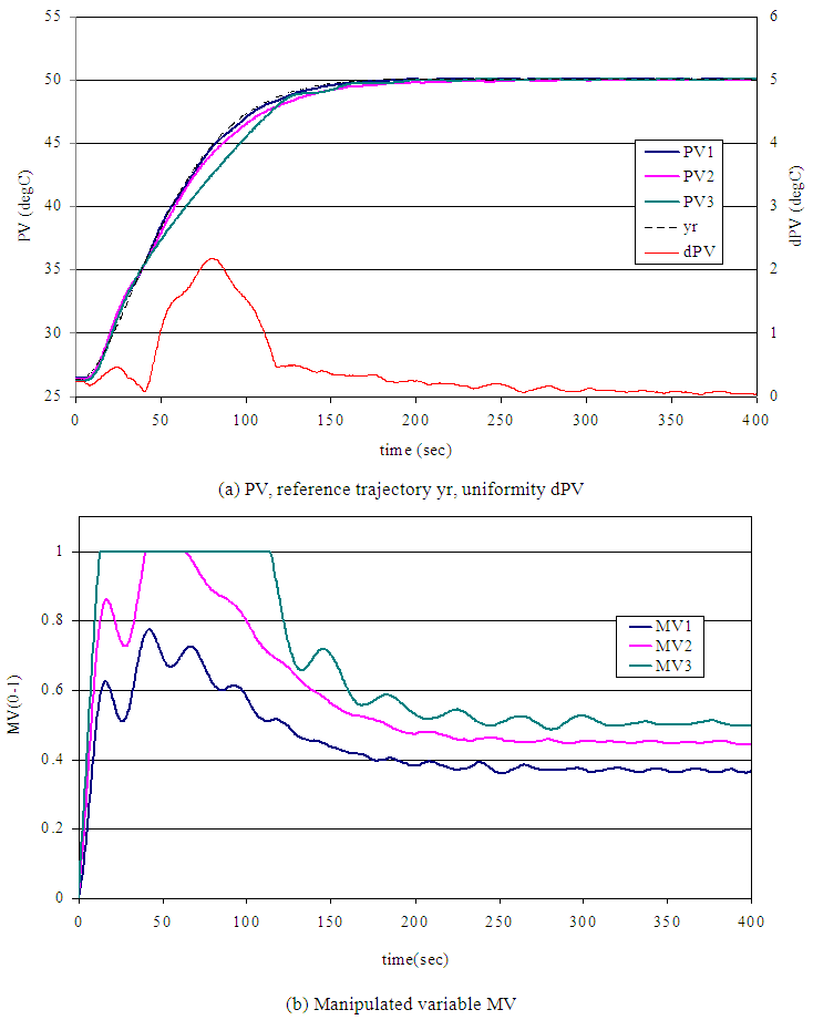 | Figure 4. Experimental result of set-point response. Reference model parameter ω0=1/30 rad/sec, ζ=0.9 |
3. Proposed Design Method
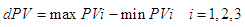
- Figure 5 shows a staircase MV pattern that achieves time optimal response. The MV should be maximum until PV reaches to a point X. After passing the point X the MV should be changed to minimum to decelerate the speed. When the PV reaches to the SV, the MV is switched to a steady state value, MVss that can keep PV at SV. There are two ways to observe switching point, one is to watch PV and switch MV at the optimal point X, another is to time and switch MV at the optimal time t1 and t2.
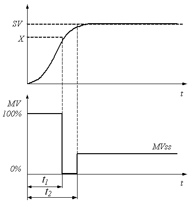 | Figure 5. Ideal manipulate variable pattern for the time optimal control |
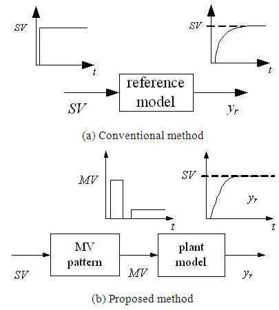 | Figure 6. Comparison of the reference model |
 | Figure 7. Experimental result for the master-slave response |
 | (14) |
4. Experiment for Validation
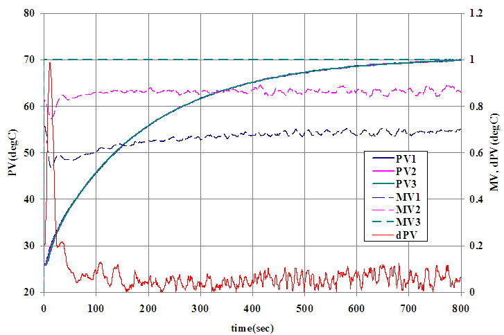
- In order to validate the effectiveness, the proposed method was applied to the test plant controller and the same experiment shown in section 2 was conducted.1) Master-Slave step response experimentZone 3 was the slowest zone and assigned as master zone. Under the master-slave PID control configuration, maximum MV was set to the master zone and made rest of the zones follow. Figure 7 shows the result. Since MV3 for the master zone is maximum, this response is the fastest that can maintain uniformity of PVs. The uniformity after 50 seconds form the beginning is less than 0.1 deg C.2) System IdentificationA first order plus dead time model was identified as (15).
 | (15) |
 | (16) |
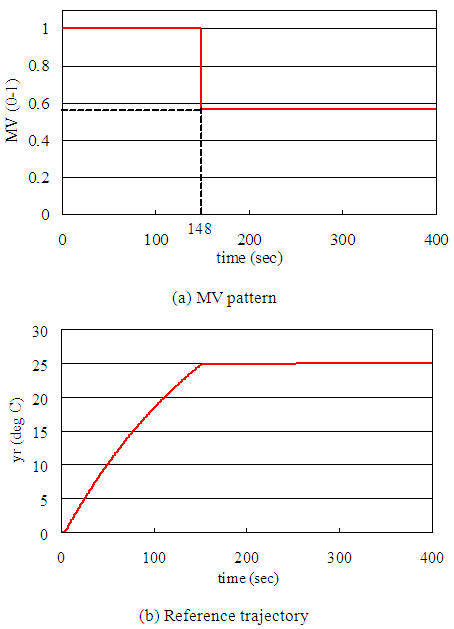 | Figure 8. MV pattern and reference trajectory |
 | (17) |
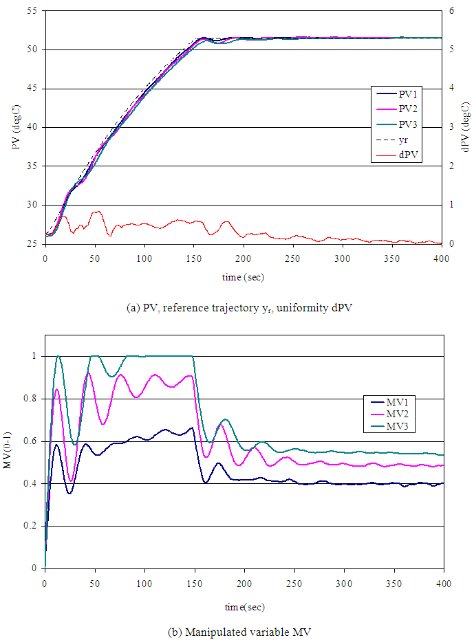 | Figure 9. Experimental result of proposed method |
5. Conclusions
- We proposed a simple yet practical design method of reference model for the MFS control. It is suitable for the MIMO system with interaction and input saturation. In this paper we first claimed disadvantages of conventional method by showing experimental result. It indicates input saturation worsens both uniformity of PVs and response speed. In our proposed method we introduced unique reference model design and input signal design. The reference model is obtained by master-slave step response test. Using this model, staircase input signal that realizes near time optimal response is obtained by simulation. We showed the effectiveness of our method by experimental result. The result showed improvement of both response speed and temperature uniformity compare to the conventional method. Future work is to create method applicable to both heating and cooling that have different dynamics.
Appendix
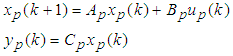
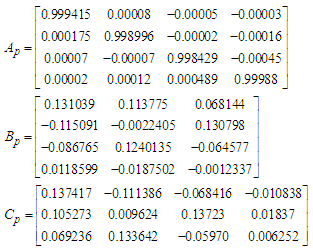
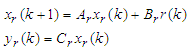
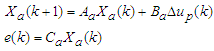
- Discrete time MFS controlConsider an m-inputs m-outputs plant

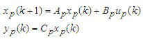
 (A1a)(A1b)where
 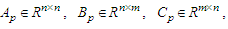 and
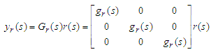
and  are states, manipulated variable, and process variable respectively. We assume (Ap, Bp) is controllable, and (Cp, Ap) is observable. A reference model is expressed m-inputs and m-outputs system shown eq. (A2).
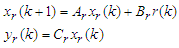
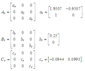
 (A2a)(A2b)where
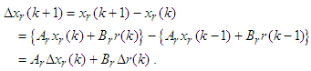
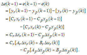
  and xr, r, yr are states, reference, and reference output respectively. We assume (Ar, Br) is controllable, (Cr, Ar) is observable, and the model is asymptotically stable. Considering difference equation of eq. (A1a) and (A2a), we obtain
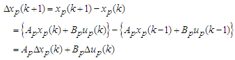 | (A3) |
 | (A4) |
 | (A5) |
 | (A6) |

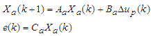
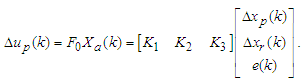
 (A7a)(A7b)Where
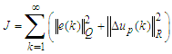
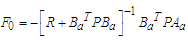
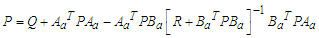
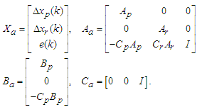 The optimal control law minimizing the performance index (A8)
 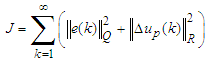 | (A8) |
 | (A9) |
 | (A10) |
 | (A11) |
 | (A12) |