Wiesław Madej
Department of Electronics and Computer Studies Technical University of Koszalin 2 Śniadeckich St. 75-453, Koszalin Poland
Correspondence to: Wiesław Madej, Department of Electronics and Computer Studies Technical University of Koszalin 2 Śniadeckich St. 75-453, Koszalin Poland.
| Email: |  |
Copyright © 2012 Scientific & Academic Publishing. All Rights Reserved.
Abstract
Specialized digital prediction systems are necessary elements of the automated system of the fire control of anti-aircraft artillery. They constitute the basic subsystem which realizes tasks of the ballistic module. This module is responsible for working out appropriate settings for performance of the fire task. In the paper the algorithm of computations and necessary functions for the proper operating of the specialized prediction system realizing prediction of the meeting point. i.e. coordinates of the point in which, according to the computations, the meeting of the target and the missile should take place, for small caliber anti-aircraft artillery are presented. This algorithm can be implemented using industrial computers, microprocessor systems containing a signal processor or a programmable logic controller (PLC) which can be programmed in the C programming language.
Keywords:
Module of the Ballistic Computations, Real Time System, Digital Prediction System, Resolver, Shooting Conditions
Cite this paper: Wiesław Madej, Specialized Digital Prediction System with a Simple Hypothesis of the Target Movement, International Journal of Control Science and Engineering, Vol. 3 No. 2, 2013, pp. 31-40. doi: 10.5923/j.control.20130302.01.
1. Introduction
The task of the prediction of the meeting point belongs to main tasks of the anti-aircraft artillery which should be performed during data preparation for shooting. Till now, this problem was carried out by analogue prediction systems, based mainly on the analogue lamp counting machines. These systems became old-fashioned and very fallible. That is why the necessity of designing of the new prediction systems, to the existing anti-aircraft artillery systems, arose, what is also the base for testing of solutions enabling designing of the prediction systems to the newly created systems. Issues connected with designing of the artillery prediction systems appear in the literature for a few years. Different aspects connected with designing of the specialized digital prediction systems are presented in papers[1-7]. In the paper[1], the author presents the influence of the lack of taking into account the corrections on the accuracy of work of the specialized prediction system. Papers[2-3] concern the analysis of the necessity of application of the appropriate filters required for the proper determination of the velocities for working out appropriate advance coordinates of the target. In papers[4, 5], authors discuss the influence of the application of the algorithms with the alternate period of sampling and accelerated algorithm of computations on the accuracy of computations of the advance coordinates of the target. However, these papers do not present the explicit functions which should be taken into account in the algorithm of computations for the exact mapping of the track of the missile flight to the target and, as a result, the correct solution of the task of their meeting. The trial of the presentation of such functions was contained in paper[6]. However, the authors, considering the full set of equations of the missile movement, state that the time necessary for computations is to long to realize such algorithm in the industrial computers or the programmable controllers. In connection with it, the necessity arose to elaborate such functions which will precisely map the track of the missile. At the same time it will influence the correctness of the solution of the issue of the hitting and will bring the possibility of realization of the function and the algorithm in the industrial computer, programmable logic controller PLC, or in the microprocessor system with a signal processor.
2. The Issue of the Prediction Task of the Meeting Point and a General Algorithm of its Solution
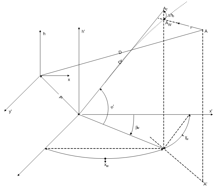 | Figure 1. Issue of the prediction of the meeting point |
Shooting to the air targets moving in the air with the high velocity and possessing maneuverable possibilities requires consideration of the advance corresponding the shift of the target in time of the flight of the missile to the target. The gun is pointed not in the point As (fig.1), where the target is in the moment of the shooting but in the point Aw being on the future track of the target in which, according to the computations, the missile should meet with the target. This point is called the meeting point. To direct a missile into the meeting point one should know its geometric coordinates, on the basis of whose the settings on the guns are determined. In order to solve the meeting task, one should know the current coordinates of the target, value and direction of the velocity vector of the target and also the character of the target movement in time of the missile flight to the meeting point.The current coordinates of the target are determined as a result of its tracing by the radiolocation station or by the optical devices. Determination of the value and direction of the velocity vector of the target, solution of the meeting task and determination of the settings on the guns are performed by the controller continuously. The worked out settings – advance azimuth and the elevation angle are transmitted to the guns continuously so they are pointed to the meeting point.
2.1. Hypothesis about the Movement of the Target
To solve the task of the meeting of the target and the missile, in a given point in space and in a given moment of time, it is necessary to know the law governing the movement of both objects and the possibility of directing one of them, in our case, by the settings of the guns. The law of the missile movement was elaborated in ballistics, and one can, with the high accuracy, know the track of the missile velocity in different points of the track and the time of the flight to different points in space. The influence of the ballistic and meteorological conditions on the flight of the missile and its position as a function of time is known. That is why after proper aiming of the gun one can get desired trajectory of the missile going through the meeting point. The law of the movement of the target for a given gunshot can be determined only to the point in space in which the target is at the moment of the gunshot – point As, during the continuous determination of the current coordinates and parameters of the movement of the target. During the continued movement, it means at the advance time, on the line segment As Aw determined law of the movement of the target can be disturbed either by the will of the pilot (in the form of the manoeuvre) or without the reasons depending on his will. One can however assume that the target, in the advance time, will keep the former character of the movement. For shorter the advance time, it will be more probable that the character of the movement in this time will differ less from the character of his movement till the moment of the gunshot. So, it follows that it is necessary to assume some hypothesis of the target movement in the advance time. Different hypothesis about the movement of the target are possible and for the needs of this paper the simple hypothesis is assumed which sounds “In the advance time the target moves along the determined straight line continuously”.
2.2. The Issue of the Task of Prediction of the Meeting Point
Prediction of the meeting point (solution of the meeting task of the target and the missile) is the essential stage of the preparation of the gunshot at the time of which the geometric coordinates of the meeting point Aw are determined. Aiming of the missile to the point As is senseless because at the time of the flight the target will move from this point for a distance  (
( – time of the flight to this point) and the meeting of the missile and the target will not happen. It results that to meet the target and the missile it is necessary to aim the missile to the point Aw lying on the course of the target in the distance about
  from the point As. The essence of the solution of the meeting task the target and the missile lies in the reconciliation in time the routes of the missile and the target coming with different velocities (constant of the target and changeable of the missile) and from different points, giving on their crossing the meeting point Aw. The solution alone lies in the determination of the geometric coordinates of the meeting point in any set of coordinates. Where: x,y,h – set of coordinates connected with the telemetric device.x’, y’, h’ – set of coordinates connected with the object of control.P – vector of the parallax
  – ballistic loweringAw – predicted meeting point
2.2.1. Prediction of the Meeting Point
In the case of the simple hypothesis about the target movement, the target in the advance time moves along the straight line with the constant velocity. When it’s right angle coordinates x, y, h and the components of the velocity are known, it is necessary to determine coordinates of the point  The algorithm of computations of the coordinates of the meeting point is the following:1. Computation of the horizontal distance to the target Dp from the gun:
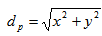 | (1) |
2. Computation of the real distance of the target D from the gun: | (2) |
3. Computation of the time of flight of the missile to the meeting point according to the ballistic tables as a ballistic function: | (3) |
In the first approximation the real distance D is taken as an ostensible distance DT defined by eqs. (5-6), a real height h is taken as an advance height hw according to eq(4).4. Computation of the coordinates of the meeting point: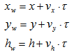 | (4) |
5. Computation of the ostensible height ht: | (5) |
where  – ballistic lowering.6. Computation of the horizontal distance to the meeting point Dpw and the ostensible distance DT:
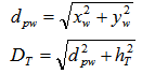 | (6) |
7. Computation of the azimuth angle  and the elevation angle
  :
:  | (7) |
Returning to point 3.
2.3. Ballistic Table and Ballistic Functions
The ballistic tables for the anti-aircraft gun are the base of the theoretical computations during solving of the problems concerning the ballistic curve of the missile. They are made on the base of experimental shooting and partially theoretical computations. In this work, the tables of the anti-aircraft gun S-60 are used. These tables include numerical data of the trajectory of the flight of the anti-aircraft missile shot by the medium worn barrel, in the so called tabular atmospheric and ballistic conditions. Influence of the deviations from the tabular conditions on the trajectory of the missile flight is inscribed as a deviations table and correction of coordinates.To the important factors decisive about movement of the missile, so factors which should be considered at the shooting, belong:– muzzle velocity v0– temperature of the gunpowder load  – kind of the missile– air density Gp– air temperature tp– components of the wind vector (longitudinal wind and crosswind) wd, wz– derivation of the missile z.Moreover, ballistic tables contain information about a natural space dispersion allowing solving the probability of the target hitting, as well as they characterize accuracy of the gun.On the basis of the ballistic tables we can reconstruct a progress of each from the following quantities as the function of one of them taking the third as a constant value:– horizontal distance Dp– real distance D– elevation angle
  – angle of the aiming
  – derivation z– time of the flight of the missile
  – gradient
  – missile velocity v– throw angle
  – deviation of the range
  – deviation of the height
  Moreover indirectly we can calculate a progress of:– ballistic drop
  – apparent distance DTApparent distance DT is a distance between a projection of any point of trajectory of the missile AT on the tangential line to the trajectory in the muzzle and muzzle point.Ballistic lowering
  is the distance between any point of a trajectory of the missile and a corresponding the apparent point AT.These two quantities above are particularly helpful to build an algorithm of the artillery resolver because of the efficiency of the computations in the resolver.To make the ballistic tables, the horizontal distance with a step 500m was taken as an independent variable, and a height with a step 500m was taken as a constant parameter. The time of the flight of the missile to the meeting point is given in these tables with an accuracy of 0.1s and with a step to 2 s. Because of a too big step and too small accuracy of the time of the missile flight the ballistic tables can not be immediately written to the computer memory in an unprocessed form. The linear interpolation can not be used because the ballistic functions are strongly nonlinear, but the interpolation taking into account nonlinear functions would require a large number of nonlinear auxiliary functions in the resolver's algorithm.Under the assumption, that the algorithmic error of determination of the coordinates of the meeting point should not be greater than one central deviation of the natural dispersion at the middle distances of shooting (5km), i.e. about 1.5 m, the accuracy of time computation of the missile flight to the meeting point with the velocity of the target 300 m/s and the course angle 45 degrees can not be worse then 0.01s. The accuracy of time computation of the missile flight to the meeting point, like above-quoted, was taken in this work. Because the coordinates of the predicted advance point are functions of the time of the flight of the missile, the accuracies of their determination are a total differential because of the right angle coordinates of the target and its velocity vector.Therefore there exists the necessity of the approximation of the ballistic tables by the mathematical functions respectively to the algorithm of prediction of the meeting point. These functions should be relatively simple, because of the limited calculation time and should provide the necessary accuracy of calculations of coordinates of the meeting point.In the algorithm of calculations presented in point 3.1, to calculate of the current time of the flight of the missile to the meeting point, the loops of the feedbacks with adequate ballistic functions are implemented.The following form of these functions are assumed:
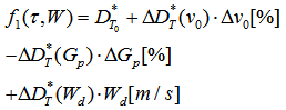 | (8) |
where: – theoretical distance from the gun to the ostensible point AT at tabular conditions of shooting
 – change of the ostensible distance for 1% change of the muzzle velocity
 – percentage deviation of the muzzle velocity
 – change of the ostensible distance for 1% change of the air density
 – percentage deviation of the air density
 – change of the ostensible distance for 1 m/s change of the longitudinal component of the wind velocity
 – value of the longitudinal component of the velocity of the wind
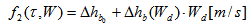 | (9) |
where: – theoretical value of the ballistic lowering with tabular conditions of shooting
 – change of the ballistic lowering for the change of the longitudinal component of the velocity of the wind equal to 1m/s
 | (10) |
where: – correction of the advance azimuth for the rotational movement of the missile
 – change of the advance azimuth for the component of the crosswind equal to 1m/s
 – value of the component of the crosswind
 | (11) |
This function is an empty set under the assumption that leveling of the gun is correct. The explicit expressions representing these functions above are not published anywhere.Functions presented in this work approximate the ballistic tables with the accuracy not worse than 0.3% of the time of the missile flight to the meeting point at the height to 1500 m and not worse than 0.5% of the flight time of the missile to the meeting point at the height bigger than 3000 m.Considering the fact that the time of the missile flight to the meeting point given in the ballistic tables is rounded up to 0.1 s we can state, that above-quoted functions guarantee attainment of the required prediction accuracy of the meeting point. In the resolver, the deviation of the missile weight is not taken into account because of the little impact in the zone of fire. Deviation of the air temperature one can take into account indirectly by the numeral coefficient as an additional deviation of the air density.The algorithm of the resolver should be designed to enable computation and transmission of the coordinates of the gun settings in the real time, with frequency not lower than 50 points per second.Mathematical equations of the resolver algorithm can not have singular points even of the first kind in the interval of the possible values of variables and parameters.Because meteorological deviations of the tabularized conditions of the shooting depend on the height of the target, therefore one should input to the resolver, during preparation to the shooting, necessary data for various heights, and during the shooting a system should automatically select adequate corrections.Because of the practical reasons the most typical method of deviation determination of the muzzle velocity is to solve it using the elongation of the missile chamber  or from the number of the gunshots (N).The functions of the deviation of the muzzle velocity
  or
or  are given in the tabular form in ballistic tables.It is advisable to write to the computer memory the complete set of tables and algorithm of the computations, on their basis, of the summary deviation of the muzzle velocity from the tabular value.
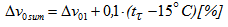 | (12) |
Similarly the summary ballistic deviation of the air density taken into account in the resolver is a sum of a few components: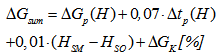 | (13) |
where:HSM – altitude of the meteorological station Hso – altitude of the fire position – correction for the sort of the missile
 – deviation of the air temperature at the determined height
 – deviation of the air density at the determined height
3. The Ballistic Functions
During the work, the resolver determines the following ballistic functions:√ time of the flight of the missile to the meeting point as a function of the distance and the height of the target – Fig. 2 – as a result of iterations;√ the ostensible distance DT0 according to the formula: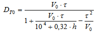 | (14) |
√ correction of the ostensible distance with the change of the muzzle velocity  – Fig. 3 – from the formula:
 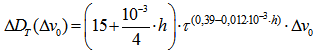 | (15) |
√ correction of the ostensible distance with the change of the air density  – Fig. 4 – from the formula:
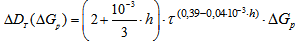 | (16) |
√ correction of the ostensible distance with the change of the longitudinal component of the velocity of the wind from the formula: 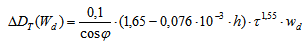 | (17) |
√ the ballistic lowering  from the formula:
  | (18) |
√ correction of the height with the change of the longitudinal component of the wind velocity – fig. 5 – from the formula: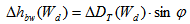 | (19) |
√ correction of the advance azimuth for the rotational movement of the missile  for various heights from the formula:
 | (20) |
√ correction of the advance azimuth for the component of the crosswind  from the formula:
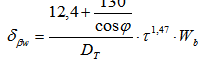 | (21) |
 | Figure 2. Time of the flight of the missile to the meeting point as a function of the distance and the height of the target |
 | Figure 3. Correction of the ostensible distance with the change of the muzzle velocity  |
 | Figure 4. Correction of the ostensible distance with the change of the air density  |
 | Figure 5. Correction of the height with the change of the longitudinal component of the wind velocity |
4. Algorithm of the Meeting Point Prediction
4.1. Procedure of Computation
Settings of the gun, in the digital controller, are computed with the assumption of the straight line movement of the target with a constant velocity. During the first 3 seconds of the controller work, only the reading of the input data and smoothing of the right-angle coordinates of the target and computing of right angle coordinates vx, vy, vh of the velocity vector are performed. Next, the full algorithm of the digital controller is turned on.The algorithm of computations of the digital resolver is the following:1. Taking data: right angle coordinates of the target x, y, h2. Computation of the smoothed right angles coordinates of the target xc, yc, hc3. Computation of right angle coordinates vx, vy, vh of the velocity of the target and the velocity of the target vc4. Computation of the deviation of the air density  5. Computation of the coordinates of the wind: longitudinal Wd and crosswind Wb for the meeting point from the formulae
 where:W – velocity of the wind
 – azimuth of the wind
 – azimuth of the meeting point6. Computation of
 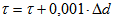 where
where  – difference computed in point 19. When the algorithm starts
  =1.7. Computation of the coordinates of the meeting point xw, yw, hw from the formula:
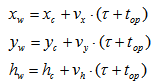 where top – time of the delay introduced by the input filters8. Computation of the ballistic lowering
  (18) and the correction of the height for the change of the longitudinal component of the wind
  (19)9. Computation of the height of the ostensible point as a sum:
 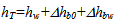 10. Computation of the horizontal distance to the meeting point
  from the formula:
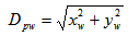 11. Computation of the elevation angle of the ostensible point
  from the formula:
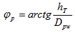 12. Computation of the azimuth of the meeting point
  as a function
  13. Computation of the distance to the ostensible point
 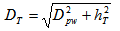 14. Computation of the ostensible distance as a ballistic function (14)15. Computation of the correction
  of the ostensible distance with the change of the muzzle velocity (15)16. Computation of the correction
  of the ostensible distance with the change of the air density (16)17. Computation of the correction
  of the ostensible distance with the change of the longitudinal component of the wind (17)18. Computation of the summary correction of the ostensible distance
  as a sum of the corrections computed in points 15, 16, 17 and adding of this to the ostensible distance DT019. Computation of the difference
  20. If the module of the difference
  returning to the point 6 else going forward21. Computation of the correction of the advance azimuth for the rotational movement of the missile
  (20)22. Computation of the correction of the advance azimuth for the component of the crosswind
  (21)23. Addition corrections computed at the points 21 and 22 to the azimuth of the meeting point24. If the azimuth of the meeting point is larger or equal than
  recount the azimuth to the interval
  25. Displaying the coordinates of the target and the meeting point 26. Returning to point 1.The deviations of the air density, azimuth and the velocity of the wind are computed based on the data of the meteorological announcement.
4.2. Receiving, Processing and Filtering of the Input Data
The input data are values of the right angle coordinates of the target x, y, h received from the telemetric device. These values are given on the inputs of the controller, and next given on the inputs of the smoothing filter of the second order with the analogue transmittance: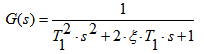 | (22) |
where:T1 – time constant of the filter – coefficient of suppressions– complex variable realized as a digital filter obtained through the bilinear transformation putting[15]
 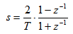 | (23) |
where T – sampling periodAfter smoothing, these data are taken by the program realizing prediction of the meeting point as smoothed right angle coordinates xc, yc, hc.The right angles coordinates of the velocity vector are computed on the basis of the right angles coordinates of the target by giving them to the inputs of the equivalent derivative digital filter of the second order with the analogue transmittance: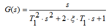 | (24) |
This filter is realized as a digital filter obtained by the bilinear transformation like a smoothing filter (23).Finally, the velocity vector coordinates are computer from the dependence: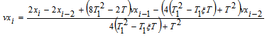 Where:T1 – time constant of the filter
 – coefficient of suppressionvxi, vxi-1,vxi-2 – values of the velocity vector components (coordinate x) in times: i, i-1, i-2xi, xi-2 – right angles coordinates of the target in times: i, i-2For the remaining components of the velocity vector the formulae are analogical.The components of the velocity vector are taken by the program realizing prediction of the meeting point.
4.3. Testing of the Algorithm
Preliminary investigations of the correctness of the algorithm were performed in the laboratory and they were based on the introduction of the test data contained in a ballistic tables and checking of the results of computations with the functions contained in the resolver. As a result of static investigations (for the static target) the obtained errors of the angels of the azimuth and elevation were smaller than 1 mrad. For the dynamic investigation (for the moving target) errors of the same angels were smaller than 2 mrad.The algorithm was tested for two cases: not moving target and a moving target. The test program was implement in the C language. For the not moving target, its coordinates, like the tested coordinates in the ballistic tables, were introduced to the inputs of the computer. During simulation, the results of computation were compared (i.e. time of the flight of the target, azimuth of the meeting point and the elevation of the ostensible point) with the tabulated data from the ballistic tables. For all tested data the relative error of theoretical data and data received as results of computations was not worse then 0,5%. In the second case tests were realized for the target moving along the straight lines with different velocities. For example results of the test for the target moving with the velocity 100 m/s at the height 500 m along the y axis are presented in Fig. 6 – Fig. 9. The last tests were proceeded on the anti aircraft range during shooting to real targets. All tests on the anti aircraft range were successful.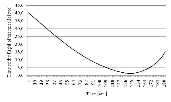 | Figure 6. Results of the test for the moving target – time of the flight of the shell versus time of observation |
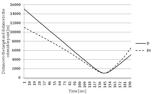 | Figure 7. Results of the test for the moving target – distance to the target and distance to the ostensible point versus time of observation |
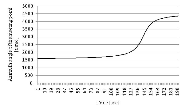 | Figure 8. Results of the test for the moving target – azimuth of the meeting point versus time of observation |
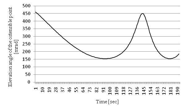 | Figure 9. Results of the test for the moving target – elevation angle of the ostensible point versus time of observation |
5. Conclusions
In this work, the procedure of proceeding with designing of the specialized digital control system destined for the anti aircraft artillery was presented. The ballistic functions for the S-60 gunfire and the algorithm of computations for the simple hypothesis of the moving of the target was presented. The algorithm was verified and tested for the moving and not moving target. The algorithm was tested for the target moving along the straight lines with different velocities. The correctness of the algorithm was tested and one can affirm that using the algorithm with ballistic functions and the functions of corrections presented in this work guarantee the accurate solving of the issue of the hitting with acceptable errors and in the time adequate for realization of this task.
References
| [1] | Borowczyk W., Kaczmarek W. (2005) Study of impact of corrections on calculation exactness of sectional settings basing on simplified ballistic tables. Biuletyn WAT, Vol. LIV, nr 9, pp. 39-48 |
| [2] | Borowczyk W. (2005) Analysis of usability of different filters advance determination of target coordinates and methods for theirs elaboration. Biuletyn WAT, Vol. LIV, nr 9, pp. 23-37. |
| [3] | Borowczyk W. (2005) Analysis of influence of grade of used digital filters for advance determination on accuracy of hitting problem solution. Biuletyn WAT, Vol. LIV, nr 9, pp. 5-21. |
| [4] | Borowczyk W., KaczmarekW. (2008) Analysis of calculation of gun-setting errors using time-variable algorithm. Biuletyn WAT, Vol. LVII, nr 1, pp. 7–18 |
| [5] | Borowczyk W., Kaczmarek W. (2008) Analysis and calculation gun-setting errors in sights of anti- aircraft artillery systems of close range. Biuletyn WAT, Vol. LVII, nr 1, pp. 19–30 |
| [6] | Machowski, B. ; Motyl, K. (1998) Analysis of development possibility of resolver for artillery system on the basis of missile motion equation. Biuletyn WAT, 548 (4), pp. 109-117 |
| [7] | Borowczyk W., Kaczmarek W. (2007) Calculation of current co-ordinates of aerial target based on the coordinates measured by distant tracking systems. Biuletyn WAT, Vol. LVI, nr 3, pp. 211–228 |
| [8] | Madej W.(2009) Measuring Errors’ Spectrum of the Artillery Radar Stations. Defence Science Journal, 59 (2), pp. 162-165 |
| [9] | Madej W., Drabarek J. (2008) Realization of reading out of coordinates in the specialized digital predictive system with the application of the reprogrammable digital circuits. Elektronika, nr 11, pp. 189-190 |
| [10] | Bartkiewicz S., Madej W. (2001) Błędy strzelania jako miara jakości zintegrowanego systemu uzbrojenia’, KKM Warszawa, pp. 577 – 580 |
| [11] | Bartkiewicz S., Ociepa Z., Boroń S., Madej W. (1995) The Digital realisation of a selsyn’s connection- V Krajowa Konferencja„Automatyzacja i eksploatacja systemów sterowania” |
| [12] | Boroń S., Madej W., Bartkiewicz S., Ociepa Z. (1995) Artillery digital controller - V Krajowa Konferencja„ Automatyzacja i eksploatacja systemów sterowania” |
| [13] | Madej W., Boroń S., Bartkiewicz S., Ociepa Z. (1995) The potential ways of improving efficiency of a anti-aircraft artillery set - V Krajowa Konferencja „Automatyzacja i eksploatacja systemów sterowania” |
| [14] | Ociepa Z., Bartkiewicz S., Boroń S., Madej W. (1995) Digital control driving system of a cannon - V Krajowa Konferencja„ Automatyzacja i eksploatacja systemów sterowania” |
| [15] | Oppenheim A.V. & R.W. Schafer. (1975) Digital Signal Processing. Englewood Cliffs, New Jersey: Prentice-Hall. |
 Abstract
 Reference
 Full-Text PDF
 Full-text HTML