Omur Akyazi1, Mehmet Ali Usta2, Adem Sefa Akpinar2
1Surmene Abdullah Kanca VHS, Karadeniz Technical University, Trabzon, Turkey
2Dept. of Electrical and Electronics Engineering, Karadeniz Technical University, Trabzon, Turkey
Correspondence to: Omur Akyazi, Surmene Abdullah Kanca VHS, Karadeniz Technical University, Trabzon, Turkey.
| Email: |  |
Copyright © 2012 Scientific & Academic Publishing. All Rights Reserved.
Abstract
In this paper, an aircraft roll control system based on autopilot operating conditions is modeled and simulated using Matlab/Simulink. The modeling phase begins with the derivation of required mathematical model to describe the lateral directional motion of an aircraft. Then, Linear Quadratic Regulator (LQR), Fuzzy Logic Controller (FLC) and Self-Tuning Fuzzy Logic Controller (STFLC) are applied for controlling the roll angle of the modeled aircraft system. Simulation results of roll controllers are presented in time domain and the results obtained with STFLC are compared with the results of FLC and LQR. Finally, the performances of roll control systems are analysed in order to decide which control method gives better performance with respect to the desired roll angle. According to simulation results, it is shown that STFLC deliver better performance than FLC and LQR.
Keywords:
Aircraft Roll Control, Linear Quadratic Regulator (LQR), Fuzzy Logic Controller (FLC) and Self-Tuning Fuzzy Logic Controller (STFLC)
Cite this paper:
Omur Akyazi, Mehmet Ali Usta, Adem Sefa Akpinar, "A Self-Tuning Fuzzy Logic Controller for Aircraft Roll Control System", International Journal of Control Science and Engineering, Vol. 2 No. 6, 2012, pp. 181-188. doi: 10.5923/j.control.20120206.06.
1. Introduction
The development of autopilots closely followed the successful development of powered man-carrying airplane by the Wright brothers[1]. The first automatic flight controller in the world is designed by the Sperry brothers in 1912. The Sperry brothers developed an autopilot that is sensitive to the movements of an aircraft. When an aircraft deviated from a particular flight route, this autopilot adjusted the pitch, roll and heading angles of an aircraft. Then, in 1914, the Sperry brothers demonstrated this autopilot at the Paris air-show. To demonstrate the effectiveness of their design, Lawrence Sperry trimmed his airplane for straight and level flight and then engaged the autopilot[1]. Since then, the fast advancement of high performance military, commercial and general aviation aircraft design has required the development of many technologies; these are aerodynamics, structures, materials, propulsion and flight controls[2]. Currently, the aircraft design relies heavily on automatic control systems to monitor and control many of the aircraft subsystems[2]. Therefore, the development of automatic control systems has played an important role in the growth of civil and military aviation[1]. Modern aircrafts are much more complex and includes a variety of automatic control system.Generally, an aircraft is controlled by three main surfaces. These are elevator, rudder and ailerons. Pitch control can be achieved by changing the lift on either a forward or aft control surface. If a flap is used, the flapped portion of the tail surface is called an elevator. Yaw control is achieved by deflecting a flap on the vertical tail called the rudder and roll control can be achieved by deflecting small flaps located outboard toward the wing tips in a differential manner[1]. These flaps are called ailerons. Elevator, rudder and ailerons are depicted in Figure 1.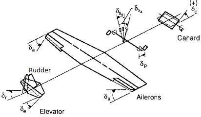 | Figure 1. Aerodynamic controls of an aircraft[1] |
The two ailerons are typically interconnected and both ailerons usually move in opposition to each other. The ailerons are used to bank the aircraft. The banking creates an unbalanced side force component of the large wing lift force which causes the aircraft’s flight path to curve[3]. Thus, when the pilot applies right push force on the stick, as the aileron on the right wing is deflected upward, the aileron on the left wing is deflected downward. As a result of this, the lift on the left wing is increased, while the lift on the right wing is decreased. So, the aircraft performs a rolling motion to the right as viewed from the rear of the aircraft.The rolling motion of an aircraft is controlled by adjusting the roll angle. In this study, an autopilot is designed to control the roll angle of an aircraft. In aircraft modeling phase, the aerodynamic forces (lift and drug) as well as the aircraft’s inertia are taken into account[4]. The actual model is a third order nonlinear system, which is linearized about the operating point[4]. A modern linear quadrature regulator (LQR) and intelligent controllers (FLC and STFLC) are developed for the roll control of the modeled aircraft system. Performances of these controllers are analysed with respect to the desired roll angle. Comparison of these control theory is presented and discussed in terms of performance analysis.
2. Modeling of A Roll Control System
The equations governing the motion of an aircraft are very complicated as a set of six nonlinear coupled differential equations. However, under certain assumptions, they can be decoupled and linearized into the longitudinal and lateral equations. Roll control is a lateral problem and this work is developed to control the roll angle of an aircraft for roll control in order to stabilize the system when an aircraft performs the rolling motion. The roll control system is shown in Figure 2.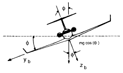 | Figure 2. Description of roll control system[1] |
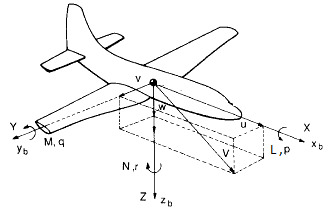 | Figure 3. Definition of forces, moments and velocity components in a body fixed frame[1] |
In this figure, Yb and Zb represent the aerodynamics force components,ϕ and δa represent the orientation of aircraft (roll angle) in the earth-axis system and aileron deflection angle respectively. The forces, moments and velocity components in the body fixed frame of an aircraft system are shown in Figure 3 where L, M and N represent the aerodynamic moment components, the term p, q and rrepresent the angular rates components of roll, pitch and yaw axis and the term u, v and w represent the velocity components of roll, pitch and yaw axis.Referring to Figure 2 and Figure 3, the rigid body equations of motion are obtained from Newton’s second law, see[1]. But, a few assumption and approximation need to be considered before obtaining the equations of motion. Assume that the aircraft is in steady-cruise at constant altitude and velocity, thus, the thrust and drag cancel out and the lift and weight balance out each other. Also, assume that change in pitch angle does not change the speed of an aircraft under any circumstance[4]. Under these assumptions, the lateral directional motion of an aircraft is well described by the following kinematic and dynamic differential equations.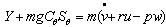 | (1) |
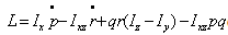 | (2) |
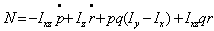 | (3) |
Equation (1), (2) and (3) are nonlinear and they can be linearized by using small-disturbance theory. According to small-disturbance theory, all the variables in the equation (1), (2) and (3) are replaced by a reference value plus a perturbation or disturbance, as given in equation (4).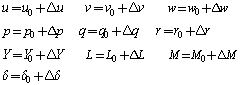 | (4) |
For convenience, the reference flight condition is assumed to be symmetric and the propulsive forces are assumed to remain constant. This implies that,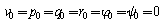 | (5) |
After linearization the following equations are obtained, see[1].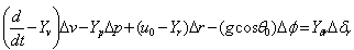 | (6) |
 | (7) |
 | (8) |
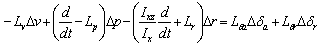
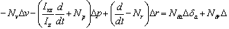
The lateral directional equations of motion consist of the side force, rolling moment and yawing moment equations of motion. It is sometimes convenient to use the sideslip angle Δβinstead of the side velocityΔv. These two quantities are related to each other in the following way;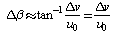 | (9) |
Using this relationship and if the product of inertia Ixz=0, the lateral equations of motion can be rearranged and reduced into the state space form in the following manner.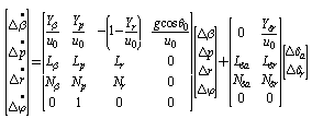 | (10) |
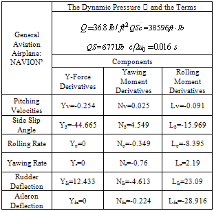
For this system, the input will be the aileron deflection angle and the output will be the roll angle. In this study, the data from General Aviation Airplane: NAVIONa[1] is used in system analysis and modeling. The lateral directional derivatives stability parameters for this airplane are given Table I.Table 1. The lateral directional derivatives stability parameters
 |
| |
|
Before obtaining transfer function, let’s plug in numerical values given Table I by using equation (10). This work presents the roll control schemes for roll angle of an aircraft system. So, the rudder deflection given in equation (10) is not used.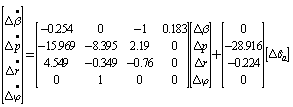 | (11) |
Transfer function from aileron deflection angle to roll angle is given by the following equation.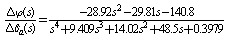 | (12) |
3. Design Process of The Proposed Controller
Fuzzy Logic Controller (FLC), Self-Tuning Fuzzy Logic Controller (STFLC) and Linear Quadratic Regulator (LQR) are proposed for the roll control system and in this section; these controllers are described in detail.
3.1. Linear Quadratic Regulator (LQR)
During last decades, a new approach to control system design has evolved. This approach is commonly called modern control theory. Linear Quadratic Regulator (LQR) is a method in modern control theory and it is an alternative and very powerful method for flight control system designing. The method is based on the manipulation of the equations of motion in state space form and makes full use of the appropriate computational tools in the analytical process[5]. LQR control system for the lateral directional control of an aircraft is shown in Figure 4.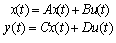 | (13) |
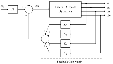 | Figure 4. Full-state feedback controller with reference input for the roll control system |
 | (14) |
So as to minimize the performance index, | (15) |
Where Q is state-cost matrix and R is performance index matrix. For this study, R=1 and Q=CTxC where C is the matrix from state equation (13) and CT is the matrix transpose of C. For designing LQR controller, the value of the feedback gain matrix, K, must be determined. The following block is shown how to determine the values of K.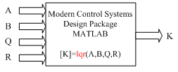 | Figure 5. Determine the values of matrix K. |
K=[0.5284, -0.5349, -0.0917 -8.6567] values are obtained by using method is depicted as Figure 5 as the weighting factor equals 75. To obtain the desired output in other words to reduce steady-state error, one must use a feed-forward scaling factor called N. Because, the full-state feedback system does not compare the output to the reference, it compares all states multiplied by the feedback gain matrix to the reference. These are shown in Figure 4. So, the reference must be scaled by scaling factor N. The scaling factor N is obtained from Matlab function that is a designer-defined function in m-file code. In this case, N=-8.6603 is determined.
3.2. Fuzzy Logic Controller (FLC)
In most research literature, a fuzzy controller system is commonly defined as a system that emulates a human expert. In this case, the knowledge of the human operator would be put in the form of a set of fuzzy linguistic rules. These rules would produce an approximate decision in the same manner a human would do. The fuzzy controller is composed of four elements. These are fuzzification, rule base, inference mechanism and defuzzification. A block diagram of a fuzzy control system is shown in Figure 6.In Figure 6, the values of error (e(k)) and its change (Δe(k)) occurring during the operation of the system form the crisp inputs of the system. These two inputs defined as in (16) and (17). | (16) |
 | (17) |
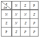
r(k), y(k) and k are expressed as the reference input, the actual output of the system and the sampling step respectively. These crisp inputs e(k) and Δe(k) are converted to fuzzy membership value on the fuzzy subsets. There are three main fuzzy subsets defined as negative (N), zero (Z) and positive (P). Depending on these subsets the number of rules can be derived.These fuzzy membership values are used in the rule base in order to execute the related rules so that an output can be generated. A rule base consists of a data table which includes information related to the system. As an example, if a fuzzy logic controller with nine rules is desired to realize, these rules can be defined in Table II.Table 2. Rules for the fuzzy logic controller
 |
| |
|
An inference mechanism emulates the expert’s decision making in interpreting and applying knowledge about how best to control the plant. Adefuzzification interface converts the conclusions of the inference mechanism into the crisp inputs for the process. A general overlooked view of the FLC is given in Figure 7 where the processes from inputs e and Δe to output Δu are shown. The input data blocks to represent fuzzy membership functions for the error e, error change ∆e and the controlled output change ∆u are shown in Figure 7. The user is able to edit and change the parameters of the membership functions on this stage without going into the detail of the FLC.Figure 7The input and output of the FLC.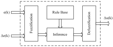 | Figure 6. The basic structure of fuzzy logic based controller |
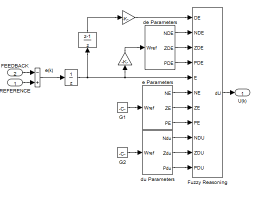 | Figure 7. The input and output of the FLC |
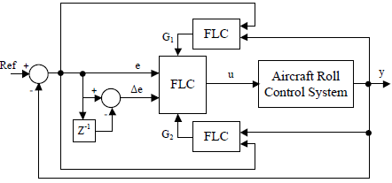 | Figure 8. The structure of Self-Tuning FLC |
3.3. Self-Tuning Fuzzy Logic Controller (STFLC)
STFLC is developed to improve the controller performance by tuning the range values of fuzzy subsets of error and its change used in direct fuzzy controller. The symbols of on-line changing fuzzy gains are G1 and G2 respectively for error (e) and change of error (Δe). In order to adjust the gain parameters G1 and G2, two different fuzzy logic controllers are used[8]. The inputs of gain-adjusting FLCs are system output and error signal which is the difference between system output and reference signal. Structure of self-tuning FLC is shown in Figure 8.
4. Simulation and Results
An aircraft roll control system is simulated using LQR, FLC and Self-Tuning FLC in order to present and discuss simulation results. Simulink model of the system with these controllers is shown in Figure 9. 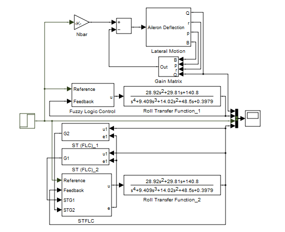 | Figure 9. Simulink model of the system with three proposed controllers. |
For all simulations, the reference value is selected as 0.15 radian which is equal to 8.625 degrees. Firstly, the various membership functions of FLC are examined and the best membership function for this system is determined. Figure 10 shows the comparison of membership functions.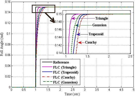 | Figure 10. The system response with various membership functions |
It is observed that the triangle membership function gives the best response as compared to others. After determining the membership function, the various rule tables of FLC is examined to understand which fuzzy rule table gives better response. FLC with nine rules gives better response than others. It is shown in Figure 11.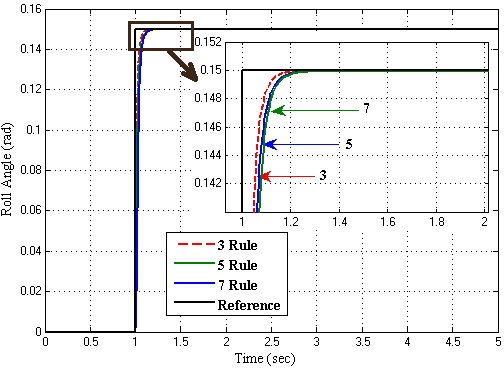 | Figure 11. The system response with various fuzzy rule tables |
Obtained fuzzy rule table and membership function which gives the best response for this system is used with both FLC and Self-Tuning FLC. Then the system responses of LQR, FLC and Self-Tuning FLC are plotted on the same graph for a better comparison. The system responses with these controllers are shown in Figure 12.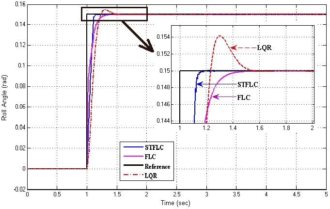 | Figure 12. The performance comparison of proposed controllers |
It is observed that STFL controller gives faster response as compared to FLC and LQR in terms of rising time. But, the results clearly demonstrate that LQR controller is occurred overshoot more than FLC and STFLC.
5. Conclusions
In this paper, the model of an aircraft roll control system that is helpful in developing the control strategy for an actual aircraft system was designed for Matlab/Simulink environment and control methods were proposed for this system. LQR, FLC and Self-Tuning FLC are successfully designed and presented for this system. As a result, among these controllers, STFLC gives the best performance in terms of rising time, settling time, steady-state error and percent overshoot. According to the results from simulation and analysis, STFLC has good and acceptable performances.
References
| [1] | R. C. Nelson, 1998, Flight Stability and Automatic Control, McGraw Hill, Second Edition. |
| [2] | Lucio R. Riberio and Neusa Maria F. Oliveira, “UAV Autopilot Controllers Test Platform Using Matlab/Simulink and X-Plane”, 40th ASEE/IEEE Frontiers in Education Conference, October 27-30, 2010, Washington, DC. |
| [3] | M. A. Usta, O. Akyazi and A. S. Akpinar, “Aircraft Roll Control System Using LQR and Fuzzy Logic Controller”, International Symposium on INnovations in Intelligent SysTems and Applications (INISTA 2011), pp. 223-227, June 15-18, 2011, Istanbul, Turkey. |
| [4] | Nurbaiti Wahid and MohdFua’adRahmat, “Pitch Control System Using LQR and Fuzzy Controller”, 2010 IEEE Symposium on Industrial Electronics and Applications (ISIEA 2010), October 3-5, 2010, Penang, Malaysia |
| [5] | Mıchael V. Cook, 2007, Flight Dynamics Prıncıples, Elsevıer, Second Edition. |
| [6] | I. H. Altas and A. M. Sharaf, “A Generalized Direct Approach for Designing Fuzzy Logic Controllers in Matlab/Simulink GUI Environment”, Accepted for publication in International Journal of Information Technology and Intelligent Computing, Int. J. IT&IC no.4 vol.1. |
| [7] | Joao P. Hespanha, April 1,2007, Umdergraduate Lecture Notes on LQG/LQR Controller Design. |
| [8] | S. Ramesh and A. Krishnan, “A Self –Tuning Fuzzy Logic Controller for a Frequency Stabilization in a Parallel AC – DC Two Area Interconnected Power System”, European Journal of Scientific Research ISSN 1450-216X Vol.51 No.1 (2011), pp.6-17, © Euro Journals Publishing, Inc. 2011 |
 Abstract
 Reference
 Full-Text PDF
 Full-Text HTML