-
Paper Information
- Next Paper
- Previous Paper
- Paper Submission
-
Journal Information
- About This Journal
- Editorial Board
- Current Issue
- Archive
- Author Guidelines
- Contact Us
International Journal of Control Science and Engineering
p-ISSN: 2168-4952 e-ISSN: 2168-4960
2012; 2(5): 102-110
doi: 10.5923/j.control.20120205.02
Applications of Fuzzy Supervisory PID Controller to a Power System
 Abstract
 Reference
 Full-Text PDF
 Full-Text HTML
G. Shabib
Faculty of Energy Engineering, Aswan University, Aswan, 81528, Egypt
Correspondence to: G. Shabib , Faculty of Energy Engineering, Aswan University, Aswan, 81528, Egypt.
| Email: |  |
Copyright © 2012 Scientific & Academic Publishing. All Rights Reserved.
This paper presents a way that fuzzy logic can be used in high level control functions. Specifically, we examine the use of fuzzy logic in supervisory control, for selecting discrete control actions, identifying the operating environment and evaluating controller performance. Proportional integral derivative (PID) controllers are widely used in excitation control of power systems, they exhibit poor performance when the controlled systems contain unknown linearities. The main objective of this paper is to simulate the use of fuzzy logic to provide new control functions that are outside the domain of the PID control-where fuzzy control is likely to provide the greatest payoff. Simply, a supervisory correction term is added to the input of the PID controller. The supervisory correction term is the output of fuzzy supervisory controller. A performance demonstration of the proposed scheme via the excitation control of a single-machine infinite-bus system subjected to a wide variety of transient disturbances is presented in this paper. Our results show that the fuzzy supervisory PID controllers have high performance compared to PID controllers with significant reduction in overshoot and undershoot. The scheme can be easily implemented in practice by adding a fuzzy supervisory controller to the existing PID controller
Keywords: PID Controller, Dynamic Stability, Fuzzy Logic Control, Supervisory Control, Single-Machine with Infinite-Bus
Cite this paper: G. Shabib , "Applications of Fuzzy Supervisory PID Controller to a Power System", International Journal of Control Science and Engineering, Vol. 2 No. 5, 2012, pp. 102-110. doi: 10.5923/j.control.20120205.02.
Article Outline
1. Introduction
- PID controllers are widely used to generate supplementary control signals for the excitation control system as well as the speed governor system in order to damp out the low frequency electro-mechanical oscillations (0.2-2.5Hz). It is also used in existing power systems to enhance their dynamic stability. Since the power system is nonlinear, PID controllers with fixed parameters suffer from poor performance when applied directly to the excitation control system. The nonlinearities in power system are due to the fact that their parameters are constantly changing because of load variations and its configurations[1-4]. When a large fault occurs, the behavior of the power system also changes. A linear controller design based on an approximate linearized model may not provide satisfactory results over a wide range of operating conditions. For this reason, the scope of this study is extended to deal with the unknown nonlinearities to control power system. Applications of new techniques based on expert system, neural network, optimal control techniques and rule based fuzzy logic for PID controller designs are used to face system conditions which is far beyond the design of existing PID controllers.Optimal control techniques are used to control power systems with nonsmooth nonlinearities[5, 6]. Successful application of the optimal control to enhance power system dynamic stability requires that the constraints imposed by power system nonlinearities should be used effectively and a limited number of feedback signal included. These methods utilize a state space representation of power system model to design different controller structure. However utilities prefer to use conventional PID controllers due to their simple structure and reliability[1].Many of fuzzy control researches in the field of power system focus on the design of fuzzy controller with a set point error and error change as their input. The output is a signal added to the AVR loop. In this situation fuzzy control is not very different from PID controller, its output is the same as PID controller output, except that fuzzy control provides nonlinear input/output mapping[7]. Hence, fuzzy control is often viewed as a form of nonlinear PID control. Comparisons between fuzzy control and PID control have been done in many studies. The performance improvement offered by fuzzy PID controller is well established and can solve most of the control problems at minimal cost; with a little incentive to switch from PID control to a more complex nonlinear form of PID control.The purpose of this paper is to examine how fuzzy logic can be used in control applications beyond fuzzy PID control[8-14]. In particular, the emphasis here is on the use of fuzzy logic to perform high level control functions that fall outside the domain of PID controls. A design philosophy reflected in this paper to prove that fuzzy methods can be used efficiently to complement control methods for performance improvement. This paper aims at finding how to compensate for overshoots and undershoots in transient response.
2. Power System Model
- The power system considered in this study is a single -machine connected to an infinite-bus through a transmission line as shown in Fig. (1). A fourteen orders model including the electrical network, shaft, excitation system and mechanical system is presented. The system dynamic behavior is described by a set of Parks d-q differential equations with reference frame based on the rotor[15]. The differential equations describing the different subsystems of the power system can be presented as follows:1. Machine windings is represented by fifth order and given by:
 | (1) |
 , while X1, R1, V1 and X2 are parameter matrices ( see appendix A1 ).2. The IEEE Type ST1 excitation system is used in this study[15]. It can be represented as follows
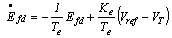 | (2) |
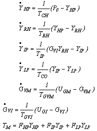
 5.0 pu in this study.3. The mechanical shaft is represented by a second order swing equation as follows
 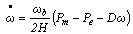 | (3) |
 | (4) |
 | (5) |
 | (6) |
 | Figure (1). Power system equipped with supervisory fuzzy PID controller |
 is a vector of the state variables,
  is an input vector representing the output of the exciter Efd ,
  is a set of non-linear functions describing the differential equations of the complete power system under study.
3. Fuzzy Supervisory PID Controller
- Fig. (1) illustrates the basic control structure of power system equipped with supervisory fuzzy PID controller. The scheme consists of a PID control structure together with our proposed fuzzy supervisory control. The fuzzy supervisory control uses the output speed deviation
 and the shifted speed deviation
  to generate the supervisory command signal.
 | (7) |
 | (8) |
 | (9) |
 | (10) |
 is the tracking error between the reference output
  and the output of the synchronous generator
 is the change in the tracking error. The term
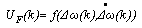
  is a nonlinear mapping of
  based on fuzzy logic routine. This is to be described in the next section.The term
  represents a supervisory or correction term, so that the supervisory control signal e’(k) is simply the sum of the external commands
  .The correction is based on the error
  and the change of error
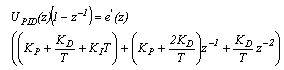
 .The supervisory command signal e’(k) is applied to a PID controller as shown in Fig. 1. The supervisory command signal can be written as follows;
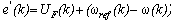 | (11) |
 | (12) |
 can be written as follows:
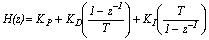 | (13) |
 | (14) |
 | (15) |
 | (16) |
 and the output speed
  of the power system. The purpose of the fuzzy supervisory is to modify the command signal to compensate for the overshoots and undershoots present in the output response when the power system has unknown linearties. Such nonlinearities result in significant overshoots and undershoots if an existing PID control scheme is used.
4. Fuzzy Logic Controller
- Unlike classical control system design, which required a plant model for designing the controller, fuzzy logic incorporates an alternative way which allows us to design a controller using a higher level abstraction without knowing the plant model. This makes fuzzy logic controller very attractive for ill-defined systems or systems with uncertain parameters. The basic configuration of a fuzzy supervisory is like the fuzzy controller which is composed of three parts: the fuzzifier, the knowledge and inference decision stage and the defuzzifier. The fuzzifier maps the input values into fuzzy variables using normalized membership function and input gains. The knowledge and inference decision stage deduce the proper control action based on the available rule base. Finally, the defuzzifier transforms the fuzzy output to a crisp output using normalized membership function and output gains[16].In this paper, the rotor speed deviation
 , and its derivative
 , is considered as the inputs of the fuzzy supervisory controller. Other input signal such as the deviation in the accelerating power (electrical power or mechanical power) of the synchronous machine can be also considered.After
  and
and  signal pass through two appropriate scaling factors, they are fed to the fuzzy supervisory controller. The output signal is also scaled by passing through the output scaling factor. To convert the measured input variables of the fuzzy supervisory into suitable linguistic variables, seven fuzzy subsets are chosen. Membership functions of these subsets are triangular shape. Fig. (2) shows the membership functions for speed deviation and similar membership functions are used for the derivative of the speed deviation and for the output of the fuzzy supervisory. The fuzzy set values of the linguistic values are chosen as;[NB Negative Big; NM Negative Medium; NS Negative Small; Z Zero; PS Positive Small; PM Positive Medium; and PB Positive Big]
 | Figure (2). Membership functions |
 is zero and
  is negative small the output UF (k) is a tendency for negative small.IF
  is Z AND
 is NS then UF (k) is NSAND operation in the above rule is realized by “min” operation, i.e. = min (μ(
 ), μ(
), μ( )), other rules can be interpreted in the same way.Once the error and the change of error are translated from the crisp domain into the fuzzy environment via the fuzzification procedure, the output fuzzy sets are found using the fuzzy sets resulting from the 49 rules using union procedure. This procedure is called defuzzification. Defuzzification describes the mapping from a space of fuzzy control action into a nonfuzzy control action. There are numerous defuzzification methods; however, in this study the center-of-gravity method is used[16]. The center-of-gravity method computes the centroid of the area determined by the joint membership function of the fuzzy action. Technically this value is computed by the following formula:
 | (17) |
5. Evaluation of Effectiveness of the Proposed Fuzzy Supervisory PID Controller
- A single-machine connected to an infinite-bus system is used in this study as shown in Fig. (1). A nonlinear model of fourteen orders is used for representation of the system. A complete system representation and detailed data are given in appendix A2[17]. The performance of the proposed fuzzy supervisory PID controller was evaluated in simulation studies of a single machine infinite bus system and is compared with the cases with a PID controller and with a fuzzy logic controller. Different study cases are simulated using C++ language program to evaluate the effectiveness of the proposed control scheme in providing additional damping to the infinite machine power system. Details of this study cases are presented as follows:
5.1. Effectiveness after 15% Step Increase in Load
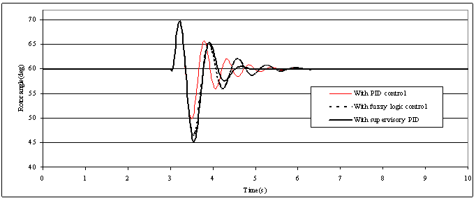
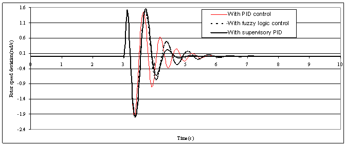
- With the single-machine connected to an infinite-bus system operates at (P=0.8 pu, Q=0.26 pu), a 15% step increase in the load (P=0.92 pu, Q=0.26 pu) is done. The parameters of the PID controller are selected to be KP =1.3, KI =30.0, and KD =-2.0001. The input scaling factors for the error and the derivative of error
 are adjusted off-line and equal to G1=2.2183 and G2 =22.2369. Figs. (3-4) show a comparison between PID control, fuzzy logic control and the proposed supervisory PID control in terms of rotor angle and rotor speed deviation. It can be seen that supervisory fuzzy PID represents a marked improvement in the amount of positive damping of rotor angle and speed deviation over PID and fuzzy logic controller. It is clear from Fig. (3) that the proposed supervisory fuzzy PID controller has virtually no overshoot, while the others controllers have significant overshoot. The supervisory fuzzy PID controller has a little oscillation but still the settling time of three controllers is approximately the same.
 5.2. Effectiveness after Long-term Operation of Sudden Change in the Output Torque
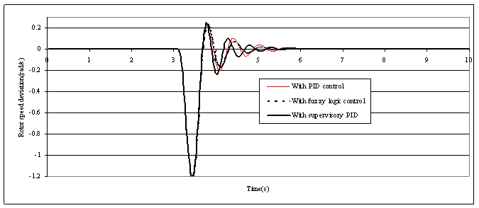
- Initially the generator is operating at a power of 0.8 pu, 0.87 power factor lagging, then it was subjected to a 15% step increase in the input torque reference at t = 3 sec, the disturbance was removed and replaced at t = 5 sec by a 15% step decrease in the input reference torque, then at t = 8 sec, the disturbance was removed and replaced by a 15% step increase in the input torque reference continued till 12 sec. Figs. (5-6) show the system time responses of rotor angle and rotor speed deviation in the case of long-term operation of sudden change in output torque. I observed that the system response in the case of supervisory fuzzy PID controller has virtually no overshoot
5.3. Effectiveness after Three Phase Faults
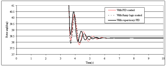
- A three-phase fault of 100ms duration is simulated at the terminal of the synchronous generator when the operating conditions of the single-machine connected to an infinite-bus system in p.u. are (P=0.8, Q=0.26). The parameters of the conventional PID controller are selected to be KP=1.3, KI =30.0, and KD =-0.50. The input scaling factors for the error and the derivative of error
 are adjusted off-line and equal to G1 =4.44 and G2 =45.4. Figs. (7-8) present the comparison of the system responses with the synchronous generator equipped with the three different types of controllers. The result shows that still the PID controller suffers from overshoot while a better result is obtained from the supervisory fuzzy PID controller.
 5.4. Effectiveness after Sudden Change in Reference Voltage
- With the single-machine connected to an infinite-bus system operated at (P=0.8 pu, Q=0.26 pu) and a step change in the AVR reference voltage is applied. Figs. (9-10) show the system responses under 20% step increase in the AVR reference voltage occurring at 3s. Fig. (9) shows the dominant part of the system responses to indicate the effectiveness of the proposed scheme under this type of fault. The rotor angle was dropped from operating rotor angle
 to a new operating rotor angle which is
  . It is noted that these simulation results indicate good dynamic behavior of the proposed fuzzy supervisory PID controller.
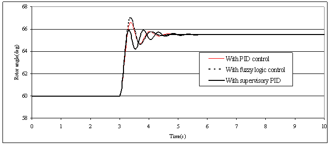 | Figure (3). Rotor angle responses to a simulated 15% step change in the load |
 | Figure (4). Rotor speed deviation responses to a simulated 15% step change in the load |
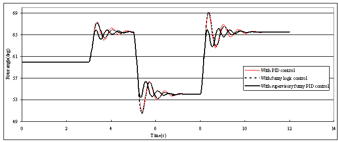 | Figure (5). Cascaded 15% step change in the load of simulated rotor angle responses |
 | Figure (6). Cascaded 15% step change in the load of simulated rotor speed deviation responses |
 | Figure (7). Rotor angle responses to a three phase short circuit for 100ms duration |
 | Figure (8). Rotor speed deviation responses to a three phase short circuit for 100ms duration. |
 | Figure (9). Rotor angle responses to a 20% step change in the reference voltage |
 | Figure (10). Rotor speed deviation responses to a 20% step change in the reference voltage |
6. Conclusions
- To improve the performances of an existing PID controller:• Fuzzy logic is used to handle the nonlinearities of the power systems.• a supervisory correction term is added to the input of the PID controller, which is the output of fuzzy supervisory controller • Results obtained in this paper showed that fuzzy logic can perform high level control functions that fall outside the domain of an existing PID controller.• We employed a fuzzy logic-based supervisory scheme for PID controllers and applied it successfully to a single-machine infinite-bus system. • The proposed control scheme has an efficient performance compared to the existing PID controller especially in reducing the overshoot of the system.• As an example; in case of 15% step increase in load study case the first swing peak of the rotor angle response is 66.53º for PID control, 67º for fuzzy logic control and 65.9º for the proposed supervisory PID control. • The advantage gained from the proposed control scheme is that an existing PID control system can be easily modified into our control structure simply by adding the fuzzy supervisor. • The proposed control scheme can be applied to a flexible AC transmission systems element (FACTS) which is suggested as future work.• The work can be extended to include multimachine power systems.
Appendix A1
- The parameter matrices R1, X1, G1, and V1 are given as follows


APPENDIX A2
- The parameters of the generating unit and the connected power system are given as follows; Generator ωb=377 rad/s, Xd =2.0 pu, Xq=1.91pu,Xfd=1.97 pu, Xkd=1.94 pu, Xkq=1.9 pu, Ra=0.005 pu,rfd =0.0015 pu, rkd=0.0078 pu, rkq=0.0084 pu, H =3.25, D =0.0 Exciter Te=0.01s, Ke=100, -5≤Efd≤5 puTurbine and governor systemFHP= 0.24, FIP= 0.34, FLP= 0.42, THP= 0.3s, TRH=10s , TIP= 0.3s, P0=1.2, TGVM= 0.1s, TGVI=0 .1sMaximum opening and closing rates for both intercept and inlet valves are restricted to =6.7 pu /s.Transmission line Re=0.063pu, Xe =0.4 puOperating pointP=0.8 pu, Q=0.45 pu, VB=1.0 puConventional power system stabilizerK =0.08, T1=10s, T2=0.15s, T3=0.05s