-
Paper Information
- Previous Paper
- Paper Submission
-
Journal Information
- About This Journal
- Editorial Board
- Current Issue
- Archive
- Author Guidelines
- Contact Us
International Journal of Control Science and Engineering
2012; 2(4): 88-92
doi: 10.5923/j.control.20120204.06
MLD Model of Boiler-Turbine System Based on PWA Linearization Approach
 Abstract
 Reference
 Full-Text PDF
 Full-Text HTML
M. Sarailoo , B. Rezaie , Z. Rahmani
Intelligent System Research Group, Faculty of Electrical and Computer Engineering, Babol University of Technology,Babol, 47148-71167 Iran
Correspondence to: M. Sarailoo , Intelligent System Research Group, Faculty of Electrical and Computer Engineering, Babol University of Technology,Babol, 47148-71167 Iran.
| Email: |  |
Copyright © 2012 Scientific & Academic Publishing. All Rights Reserved.
In this paper we consider boiler-turbine’s nonlinear dynamics and linearize the nonlinear parts based on the piecewise affine method in order to obtain a mixed logical dynamical model of the system. By using piecewise affine approach for linearization of the system’s nonlinear equations, the obtained linearized model switches between different modes based on its parameters, so acquired piecewise affine model can be categorized in the switching hybrid system class. We model the linearized boiler-turbine system in a mixed logical dynamical model of the hybrid systems using hybrid system’s description language and hybrid toolbox. Mixed logical dynamical model describes system by two linear equations and one linear inequality with a reasonable accuracy and considering the constraints in the system. We provide a comparison between the acquired mixed logical dynamical model using piecewise affine linearization method and the actual boiler-turbine system through simulation and show the efficiency of the mixed logical dynamical model to describe the Boiler-Turbine system.
Keywords: Boiler-Turbine System, Hybrid System, Piecewise Affine Method, Mixed Logical Dynamical Model, Modelling Nonlinear System
Article Outline
1. Introduction
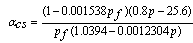
- In the study of power systems having a desirable model of system is important. A boiler-turbine system is an energy conversion system that consists of a steam boiler and a turbine which uses chemical energy to generate electricity. Boiler-turbine system model first was represented at 1972 using nonlinear equations based on the boiler-turbine plant P16/G16 at the Sydsvenska Kraft AB Plant in Malmo, Sweden[1]. A schematic diagram of the boiler-turbine unit is shown in Figure.1. After that the boiler-turbine’s nonlinear model was studied widely in many articles and was undergone a number of amends to provide a better description of system[2,3]. In order to design a controller some researchers used nonlinear form of system’s equations[5,6, 10 ] and in other works the linear form of the system was used[4,7-9].The boiler-turbine system can be modeled as a multi-input multi-output (MIMO) nonlinear system. This system is strongly coupled and is subject to various constraints on both inputs and outputs. In literatures that used the linearized form of boiler-turbine system, they obtained a linearized model using a truncated Tylor series expansion of nonlinearequations around operating points[4,7-9]. Linearization around operating points provides a relatively accurate description about system behaviour around these points, however for using of this method we should have nominal states’ and inputs’ values at operating points which are not readily available.
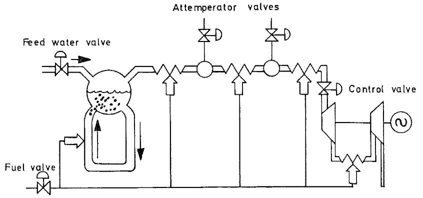 | Figure 1. schematic diagram of the boiler-turbine unit |
2. Mathematical and Linear Model of Boiler-Turbine System
- In this section, we consider the boiler-turbine system’s continuous-time dynamical equations as follow[3]:
 | (1-1) |
 | (1-2) |
 ), power output (MW) and fluid density (
 ), respectively. The inputs to the system are u1, u2 and u3 which respectively indicate to fuel flow valve position, steam control valve position and feedwater flow valve position, and have a value in the interval [0,1]. Changes in valves' position have the following limitations:
 | (2-1) |
 | (2-2) |
 | (2-3) |
 | (3-1) |
 | (3-2) |
 | (3-3) |
 ) and
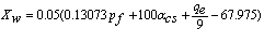
) and  is the steam quality.For obtaining the MLD model of the boiler-turbine system according equations (1), (3) and by using Hybrid Systems Description Language (HYSDEL), first the nonlinear terms in these equations must be omitted. These nonlinear terms are presented at equation (4).
 | (4) |
 | (5-1) |
 | (5-2) |
 and
and  are constant factors related to the i-th section.For example according to equation (5-1) the surface which describes the nonlinear terms f3 in the interval pf=[300,400] and p=[107.5,126.3] is as follow:
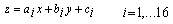
 similarly, we can obtain the linear form of equations (4) in each section. Comparisons between nonlinear and linear form of f1, f2, f3, and f4 are shown in Figure.2.Now according to linearized form of nonlinear terms, the boiler-turbine system’s dynamics can be written in the PWA configuration which Equation (6) shows general formulation of that[11].
 | (6) |
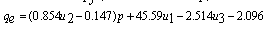
 indicates a set of conditions which defines i-th section of space (for boiler-turbine we have 64 section). Ai, Bi, hi, Ci, Di, and gi are proper time-invariant matrix related to section i. The concept of PWA model is depicted in Figure.3.In next section according to the linear discrete-time equations of boiler-turbine system, which were obtained in this section, and using HYSDEL we will acquire the MLD model of system.
 | Figure 2. comparison between nonlinear and linear form of f1 (a), f2 (b), f3 (c), and f4 (d): left pictures are showed linearized form and right pictures are showed nonlinear form |
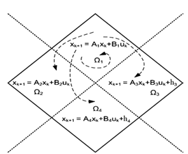 | Figure 3. a bounded PWA model: in each section linear dynamics describe system behaviour |
3. Mixed Logical Dynamical Model and Simulation
- There are many different methods for modelling of hybrid system, namely Piecewise affine, Mixed logical dynamical, Linear complementarity, and Max-min-plus-scaling[12]. Among these models, MLD method is more common and has less complexity than other methods which models hybrid system using two linear equations (7-1) and (7-2) and one linear inequality (7-3). MLD approach has the following structure[13]:
 | (7-1) |
 | (7-2) |
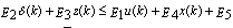 | (7-3) |
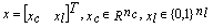 is the system state,
 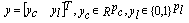 and
and  are the output and the input signal, respectively.
  denotes the logical auxiliary variables, and
  denotes the continuous auxiliary variables. The indexes c and l represent the type of the variables and respectively indicate continuous and logical.
  are proper and time-invariant matrixes.
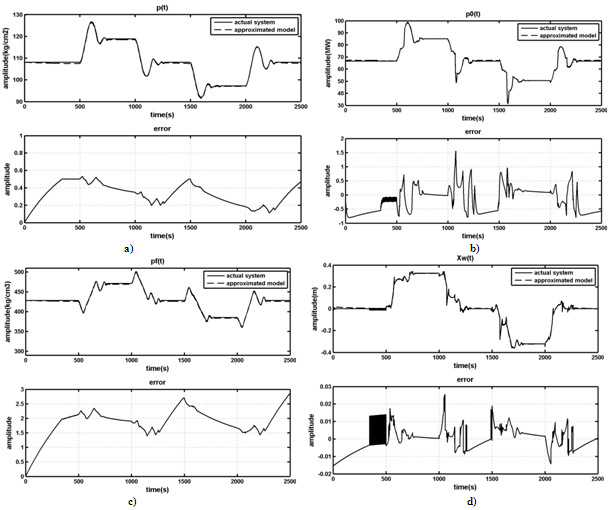 | Figure 4. actual system’s states and outputs (solid-line) in comparison of MLD model’s states and outputs (dashed-line) under identical conditions and inputs’ signals: a)drum pressure, b) power output, c)fluid density, and d)drum water level |
- Before obtaining the MLD model of boiler-turbine system based on the PWA model (equation (6)), in order to impose the inputs’ constraints that were defined at equations (2); we introduce 3 new states (8-1) and 3 new equations (8-2) as follow:
 | (8-1) |
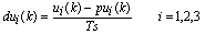 | (8-2) |
 and
and  denote the new state variable and input’s pace, respectively.Now the MLD model (7) of boiler-turbine system is obtained by using HYSDEL and hybrid toolbox[14,15]. The MLD model of the system by using PWA method for linearization has the following properties:1. Sampling time (Ts) is 1s.2. 6 states (6 continuous: -0 binary), 3 inputs (3 continuous: -0 binary), 3 outputs (3 continuous: -0 binary).3. 63 continuous auxiliary variables, 45 binary auxiliary variables, 392mixed-integer linear inequalities.In following, we provide a comparison between approximated MLD model and actual system under identical conditions and inputs signals. The results of simulation are shown in Figure.4.By looking at Fig.4, it is obvious that using piecewise affine approach for linearization describes actual system behavior at a reasonable accuracy level. In order to increase the accuracy of the MLD model of boiler-turbine system we should increase the number of partitions of the piecewise affine approach. However according to the MLD models’ properties, we should consider that increase in partitions’ number causes increase in the number of auxiliary variables and mixed-integer linear inequalities related to the MLD model. Consequently, we need more computational effort to use this MLD model in order to design a controller for the actual boiler-turbine system
4. Conclusions
- As we showed in this paper hybrid systems modelling approaches can be used not only for systems with inherently hybrid behaviours but also nonlinear systems, by using local linearization method namely PWA. We showed using MLD model method for modelling boiler-turbine system as a hybrid system makes us able to impose constraint directly into the system model and provides a very simple, systematic, and relatively accurate model of system. This accuracy comes from the PWA method which we used for linearization of nonlinear terms but increase in accuracy also causes increase in computational effort for designing a proper controller based on the MLD model. So we should make a balance between accuracy and computational cost according to our purposes and available equipments.