M. Saifizi , D. Hazry , Rudzuan M. Nor
School of Mechatronic Engineering, University Malaysia Perlis, Perlis, 02600, Malaysia
Correspondence to: M. Saifizi , School of Mechatronic Engineering, University Malaysia Perlis, Perlis, 02600, Malaysia.
| Email: |  |
Copyright © 2012 Scientific & Academic Publishing. All Rights Reserved.
Abstract
The purpose of the vision system is to recognize the circle as landmark and identify the distance and orientation in a series of reference target image automatically from the closed-range navigation. In order to identify position in an indoor environment, a mobile robot requires attention to characteristics of a target which is to allow mobile robots to make inference in which the distance and orientation of the target and a robot. In this study, fuzzy logic is applied to generate target trajectory movement with the information extracted from vision system such as the distance and the orientation of target. The fuzzy logic controller (FLC) which computes the required speed and angular speed needed by the two motors to drives the robot for target trajectory.
Keywords:
Control, Fuzzy Logic, Navigation, Differential Drive, Mobile Robot, Vision System
1. Introduction
The navigation system plays very an important role and challenging competence for mobile robot. Navigation of mobile robot includes a variety of theories and technologies such odometry technique, ultrasonic mapping, and vision system. In the application of navigation, it consists of two areas: global navigation and local navigation[1]. Global navigation such as GPS (Global Positioning System) and INS (inertial Navigation System) is often used in various open areas. Meanwhile, local navigation such as vision techniques are very effective base in the closed range navigation. There are many applications in indoor environment vehicles and mobile robots. Navigation using vision approach has many tasks, including target matching, target identification and others[1]. Practically, the use of optical sensors and image processing are the major factors affecting the accuracy of navigation[1]. In navigation application, a mobile robot must interpret its sensors data to extract environment information, with which the mobile robot can determine its position[2]. After mobile robot can localize its position, it must decide how to act to achieve its purpose. Lastly, the mobile robot must control its drive system to achieve the desired path[2][3]. The increment distance of the robot‘s movement sensed with wheel encoders is integrated to calculate position. Because measurement errors from encoders are integrated, the position error is accumulated over time. Using additional sensors can help to reduce the cumulative errors. There are many error sources of differential encoder system from environmental factors, such as misalignment of the wheels, uncertainty of wheel diameter, variation in the contact point between wheel and floor and slipping[3][4].
2. Vision Sensing
This work presents an approach using computer vision which applied feature matching technique after the image has been proceeds by Canny edge detector. Features like circular marking, the distance between two vertical lines used by the fuzzy system to analyze whether it has relation with the door being analyzed to design an expert system to detect rectangular shaped door. In this study, vision system is applied to extract the information such as the distance of target and the orientation of target.
2.1. Canny Edge Detector
In this study, the value of threshold 0.95 for Canny edge detector was chose for both low threshold and high threshold. This process provides a continuous edge and eliminates edge the streaking significant edge[5][6].
2.2. Circle Detection
The circle detection technique used in this study is a features matching technique. This technique has two steps, features extraction and representation between the features. Feature extraction is a process of extracting high-level geometric features of the curves obtained by curve extraction process. The curves and segmentation of the curves are used to create circular features.A curve is a set of edge points that are connected to form a continuous contour. Curves usually represent a boundary of the part in the image. The curve extraction process consists of three steps of finding seed point curves, tracing the curve, and refining the curves.
2.3. Distance and Orientation of Circle
By using a vision sensor to calculate the target distance (Dt) and circle orientation (θc) as shown in Equation (1) and (2) that refer in [7]. By knowing the diameter and circle center coordination of the circle, the distance and orientation of circle can be calculated. Therefore, the information distance from the target mobile robot can be known through the image circle diameter.To align the target in the world coordinate frame is to use the actual object size and the computation of object position. The set-up for this test is shown below in Fig.1. The camera is placed directly in front of the target circle.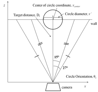 | Figure 1. The projection of the circle onto the camera image plane |
Essentially, by knowing the diameter of the circle and the calibration of the camera object distance can be measured by the length the image circle diameter. The distance between the vision sensor and the landmark is inversely proportional, k to the length the image circle diameter. Diameter circle, x’ is used to calculate the distance door-to-mobile robots. The calculation used is present in following equation: | (1) |
 | (2) |
The Equation (2) was used for the angle orientation of the landmark. The Circle landmark orientation θc by vision sensor can be calculated using the x-axis pixel position of the center point is calculated at the circle marking. The center circle coordinate, xcenter is used to calculate the angle of the circle position in the grabbing image using n and c which are constants derived from the camera calibration.
3. Mobile Robot Control System
The posture provides information about how the mobile robot moves with respect to the floor.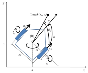 | Figure 2. Differential steering system of the mobile robot |
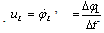
The differential steering system the mobile robot is shown above. As shown in Fig.2,(x, y): reference frame(X, Y): robot coordinates fameR: position of robot in (x, y)θ: orientation angle of robot in (x, y)r: wheel radius2d: distance between wheelsuR/L: speed of right and left wheels respectivelyv: speed of robotω: angular speed of robot : angular speed of right and left wheels respectivelyThe speed relative to the ground of the right wheel and the left wheel can be expressed as follows, respectively.
 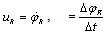 | (3) |
 | (4) |
The speed and the angular speed of a mobile robot are related to the wheel speeds, and it can be expressed as follows: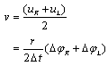 | (5) |
 | (6) |
3.1. Fuzzy Logic Controller
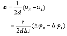
The master controller is a fuzzy logic controller (FLC) which computes the required speed and angular speed needed by the two motors to drives the robot for target trajectory.A block diagram of the fuzzy controller is shown in Fig.3. The desired θd and target distance Dt are acquired by calculating the position of the target in the image representing the environment detected by webcam camera. The command signal θd and Dt are transmitted from the vision system to the fuzzy controller inside the PC. The error between the command signal and the actual position, as well as the change in error of signal are calculated and fed into the fuzzy controller embedded in the Data Acquisition (DAQ). From the Equation (1) and Equation (2), it can be seen that the differences between the speed of the right and left wheels determines the turn speed. The fuzzy controller is designed to output pulse width modulation (PWM) signal corresponding to uR and uL to the right motor and left motor respectively to control the mobile robot turn angle θ to the desired angle θd and target distance Dt.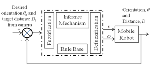 | Figure 3. A cascade control system for target trajectory |
The fuzzification procedure maps the crisp input values to the membership values between 0 and 1. In this study, three membership functions for target distance Dt and five membership functions desired angle θd was used as shown in Fig. 4 and Fig. 5 illustrate the input membership functions for Dt and θd respectively. | Figure 4. Input membership functions for target distance Dt |
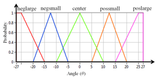 | Figure 5. Input membership functions for desired angle θd |
The rule base stores the rules relating to the knowledge input output relationship of the offered fuzzy controller. The inference mechanism is accountable for decision making in the control system using estimated sensors that give the information of the target object [8]. The operation involved in this thesis is “AND” because two inputs Dt and θd are involved. Fig. 6 and Fig. 7 show the output membership functions. Note that the output PWM signals should be selected to meet the convergence requirements. The membership of the input and output was designed based on the training of mobile robot modelling it based differential drive technique.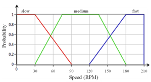 | Figure 6. Output membership functions for the speed |
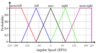 | Figure 7. Output membership functions for the angular speed |
The control rules are designed based on expert knowledge and testing. For example, if θd is “poslarge” and is Dt “far”, then the left motor should be much than the right motor, i.e., uL-uR should be “more left” and speed uL+uR should be “fast”. Based on knowledge, 15 rules were obtained. Table 1 represents how to control the turn angle given the angle and distance as inputs. The input and output linguistic variables are shown in the table.| Table 1. Table rules for the trajectory steering system |
| | | | θd | | | | Neglarge | Negsmall | center | Possmall | Poslarge | | Dt | far | more left, fast | left, fast | zero, fast | right, fast | more right, fast | | close | more left, medium | left, medium | zero, medium | right, medium | more right, medium | | too close | more left, slow | left, slow | zero, slow | right, slow | more right, slow |
|
|
4. Experiments and Results
Experiment results from distance and orientation calculation are shown in Table 2 and Table 3. Absolute and relative errors are also presented. The relative error was calculated using as following equation:| Table 2. Experimental results for the calculation of the distance to a landmark |
| | ManualMeasured[ meter] | VisionMeasured[ meter] | AbsoluteError[ meter] | Relative Error[ %] | | 1.50 | 1.52 | 0.02 | 1.33 | | 2.00 | 2.13 | 0.13 | 6.50 | | 2.50 | 2.53 | 0.03 | 1.20 | | 3.00 | 2.90 | 0.10 | 3.20 | | 3.50 | 3.40 | 0.10 | 2.85 | | 4.00 | 3.82 | 0.18 | 4.50 |
|
|
| Table 3. Experimental results for the calculation of the angle orientation to a landmark |
| | ManualMeasured[ °] | VisionMeasured[ °] | Absolute Error[ °] | Relative Error[ %] | | 27 | 22.31 | 4.69 | 17.37 | | 15 | 12.12 | 2.88 | 19.20 | | 0 | 0.01 | 0.01 | - | | -15 | 11.21 | 3.79 | 25.27 | | -27 | 22.71 | 4.29 | 15.89 |
|
|
Although the vision system is only using a single webcam, distance calculation of target showed quite accurately. The average absolute error was 0.093 meter and the average relative error was 3.26% for distance measurement. Given the measurement angle of orientation, it also revealed quite accurately with a mean absolute error of 3.16, and the average relative error of 15.66%. Referring to[7], the comparison can be made that Equations (1) and (2) can be used not only in the target in shape of a rectangular but can also be applied to the target in the shape of a circle to enable the calculation of the distance and orientation of objects using monocular vision.Due to the design of the landmarks and the usage of single webcam, the preliminary step of calibration is necessary. This calibration has to be done for the extraction of distance and orientation form an image. The usage of only one image makes it more difficult to have extremely accurate results although mathematical geometry is used the process is still dependent on camera calibration.Considering the mobile robot motion, although low error values are present in the calculation of both distance and orientation, in the robot’s movement these values will be constantly corrected. The mobile robot captures images periodically and even if some measurements have some error.By providing information from the vision system, fuzzy logic monitors the status of the robot. The robot is able to navigate in the laboratory, thus fuzzy logic controls the robot to move and position itself in the right conditions. The vision systems recognize the circle, the position of the circle and then align the robot to be in the center of the circle marking.As the performance of an autonomous robot depend on the interaction of the robot with the real world for any meaningful conclusion to be drawn, experiments have to be done to demonstrate that the robot can perform the desired tasks. Overall performance test of mobile robot was conducted to analyzed combination of fuzzy logic controller (FLC) rules with desired speed.The developed fuzzy logic control system combined with the vision system as a sensor to extract much information (target distance and target orientation) from the image to achieve a high level of self-adaptability is very important. The robot moved in different distances from the target and stop at 1.5 meter from the target because that is the minimum distance that circle can recognize.The Tables 4 and 5 show the performance of mobile robot in implementation of fuzzy logic controller. When the robot moving to the target, the results show that he average absolute error was about 0.03 meter and the average relative error was less than 3% for distance of robot to achieve it target. Given the measurement angle of orientation, it also revealed quite accurately with a mean absolute error of about 20◦, and the average relative error of about 22%.| Table 4. The orientation of the robot when arrived at target |
| | DepartureDistance[ meter] | RobotOrientation[ °] | Absolute Error[°] | Relative Error[ %] | | 6.5 | 115 | 25 | 27.78 | | 5.5 | 85 | 5 | 5.5 | | 4.5 | 60 | 30 | 33 | | 3.5 | 75 | 15 | 16.67 | | 2.5 | 65 | 25 | 27.8 | | Average | 20 | 22.154 |
|
|
| Table 5. The distance of the robot when arrived at target |
| | Departure Distance[ meter] | RobotDistance[ meter] | Absolute Error[meter] | Relative Error[ %] | | 6.5 | 1.51 | 0.01 | 0.67 | | 5.5 | 1.4 | 0.1 | 6.67 | | 4.5 | 1.47 | 0.03 | 3 | | 3.5 | 1.52 | 0.02 | 2 | | 2.5 | 1.49 | 0.01 | 1 | | Average | 0.034 | 2.668 |
|
|
5. Conclusions
Landmark recognition is not an easy task but it is very important area in developing mobile robots that is need to accomplish positioning, path planning and navigation.A robot vision system using fuzzy logic technique to identify the object in real time was presented. The system is able to find and recognize the circle and then calculate the position of the robot to navigate in a laboratory. The technique used is based on image processing and optimization in real time. It hard to an able a mobile robot navigates in indoor environment. The output is very useful for a mobile robot in real time to find and detect objects. Usually a robot vision system is very slow due to computational time used for image processing. Image processing time was minimized by the techniques used and the detection of door can be done about less than 1 second.An analysis and design of fuzzy control law for steering control of the developed nonholonomic mobile robot are presented. The proposed fuzzy controller is implemented on the developed mobile robot. The system can perform and satisfactory results are obtained which show that the proposed fuzzy controller can achieve the desired turn angle thus it can make the autonomous mobile robot moving to the target. The control system need PID controller to guarantee the stability of the straight conveying and turning trajectory.
ACKNOWLEDGEMENTS
The First of all, I would like to acknowledge the contributions of the many people who provided invaluable help and support for the completion of this thesis. My supervisor, Assoc. Professor Dr. Hazry Desa, deserve thanks for not only guiding me with a steady hand, but also leaving me the freedom to pursue my own research interests.
References
| [1] | Batlin and Maxim A, “Mobile robot navigation using a sensor network”. In: IEEE international conference on robotics and automation, 2004. |
| [2] | Saidon M.S, D. Hazry, Nagarajan R, Paul Raj MP, “Vision based tracking control of an autonomous mobile robot in an indoor environment”, Proceedings- 2011 IEEE Control and System Graduate Research Colloquium, ICSGRC 2011 (2011), Article number 5991819, Pages 1-6, 2011. |
| [3] | Saidon M.S, D. Hazry, Rudzuan M.N, ‘A Differential Steering Control with Proportional Controller for an Autonomous Mobile Robot”, Proceedings - 2011 IEEE 7th International Colloquium on Signal Processing and Its Applications, CSPA 2011 (2011), Article number 5759849, Pages 90-94, 2011 |
| [4] | D. Hazry and M. Sugisaka, “Optimal Parameter Tuning in Proportional Control for the Unicycle Mobile Robot: An Experimental Study”, Proceedings of the 11th International Symposium on Artificial Life and Robotics (AROB 2006), 2006 |
| [5] | Canny, J., “A Computational Approach to Edge Detection”, In: IEEE Transactions on Pattern Analysis and Machine Intelligence. Vol. 8, No. 6, pp. 679-698, 1986. |
| [6] | Khalil, A., A. Aggoun, A. ELmabrouk, “On Edge Detector Using Local Histogram Analysis”, In: SPIE Visual Communications and Image Processing. Vol. 5150, 2003. |
| [7] | Yoon, K.-J., G.-J. Jang, S.-H. Kim, and I. S. Kweon, “Fast Landmark tracking and localization algorithm for the mobile robot self-localization”, In: IFAC Workshop on Mobile Robot Technology, pages 190-195, 2001. |
| [8] | Driankov, D., H. Hellendoorn and M. Reinfrank, “An Introduction to Fuzzy”, Control. Springer, Berlin, 1998. |
 Abstract
 Reference
 Full-Text PDF
 Full-Text HTML