-
Paper Information
- Next Paper
- Previous Paper
- Paper Submission
-
Journal Information
- About This Journal
- Editorial Board
- Current Issue
- Archive
- Author Guidelines
- Contact Us
International Journal of Control Science and Engineering
2012; 2(4): 60-68
doi: 10.5923/j.control.20120204.02
Phase Advanced Dynamic Voltage Restorer Control System Design
 Abstract
 Reference
 Full-Text PDF
 Full-Text HTML
M. A. Taghikhani
Department of Engineering, Imam Khomeini International University, Qazvin, Iran
Correspondence to: M. A. Taghikhani , Department of Engineering, Imam Khomeini International University, Qazvin, Iran.
| Email: |  |
Copyright © 2012 Scientific & Academic Publishing. All Rights Reserved.
The increment of voltage-sensitive load equipment has made industrial processes much more susceptible to degradation in the quality of power supply. Voltage deviations, often in the form of voltage sags, can cause severe process disruptions and result in substantial economic loss. Among the several novel custom power devices, the dynamic voltage restorer (DVR) for application in distribution systems is a recent invention.The compensation capability of a DVR depends primarily on the maximum voltage injection ability and the amount of stored energy available within the restorer. In this paper a new phase advance compensation (PAC) strategy for the DVR is proposed in order to enhance the voltage restoration property of the device. Also a method of determining the exact amount of voltage injection required to systematically correct a specific voltage drop is proposed with minimum active power injection. Using the proposed method it can be shown that a particular disturbance can be corrected with less amount of storage energy compared to that of existing in-phase boosting method. Analytical expressions for both the magnitude and angle of the injected voltage are also derived. A closed-loop controller that consists of an inner current loop and an outer voltage loop is also incorporated into the DVR system. Theoretical analysis shows that the capacitor current feedback scheme is superior over the inductor current feedback scheme in terms of steady state error and disturbance rejection.
Keywords: DVR, Minimal energy control, Power quality, FACTS
Article Outline
1. Introduction
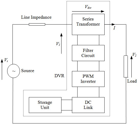
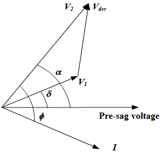
- A dynamic voltage restorer is a power quality (custom power) device used to correct the voltage disturbances by injecting voltage as well as power into the system. Voltage deviations, often in the form of voltage sags, can cause severe process disruptions and result in substantial economic loss. Therefore, cost-effective solutions, which can help such sensitive loads, ride through momentary power supply disturbances, have attracted much research attention. Among the several novel custom power devices, the dynamic voltage restorer (DVR) for application in distribution systems is a recent invention.A series-connected converter-based mitigation device DVR[1-6] has been proposed for protecting sensitive loads from such voltage sags. The series interconnection allows the DVR injected voltage to be added to the utility supply voltage. The amplitude and phase angles of the injected three-phase voltages can be varied, thereby allowing control of real and reactive power exchanged between the DVR and the distribution system. The reactive power can be internally generated without AC passive components, while the real power exchange between the DVR and the load needs to be supplied by external means. The amount of real power and reactive power provided by the DVR depends on the type of voltage disturbance, the power requirements of the protected load and the direction and magnitude of the injected voltage.The compensation capacity of a particular DVR depends on voltage injection ability and the maximum real power that can be supplied by the DVR. Thus the capacity of the energy storage device can become a limiting factor in compensating long duration voltage sags. If the DC-link energy storage can be further supplied by some means during compensation, the DVR can mitigate long duration voltage sags effectively[7]. A schematic diagram of the DVR incorporated into a distribution network is shown in Fig.1. In the figure, Vs is the source voltage, V1 is the incoming supply voltage before compensation, Vdvr is the series injected voltage of the DVR, and I is the line current[5, 6]. The restorer typically consist of an injection transformer, the secondary winding of which connected in series with the distribution line, a voltage-sourced PWM inverter bridge connected to the primary of the injection transformer and an energy storage device connected at the dc-link of the inverter bridge. The inverter bridge output is filtered in order to mitigate the switching frequency harmonics generated in the inverter. The injection of an appropriate Vdvr in the face of an up-stream voltage disturbance requires a certain amount of real and reactive power supply from the DVR. It is quite usual for the real power requirement of the DVR to be provided by the energy storage device in the form of a battery, a capacitor bank, or a flywheel. The inverter generates the reactive power requirement. Widely used in present DVR control is the so-called in-phase voltage injection technique where the load voltage V2 is assumed to be in-phase with the presag voltage. As the DVR is required to inject active power into the distribution line during the period of compensation, the capacity of the energy storage unit can become a limiting factor in the disturbance compensation process[8-11]. For sags of long duration, this could result in poor load ride-through capability but it is not necessary for V2 to be in-phase with the presag voltage[5]. Indeed, V2 vector can lie anywhere on the periphery of a circle, the radius of which equals to the amplitude of the presag voltage (Fig.2). The disturbance correction capability of the restorer depends very much on the maximum voltage injection capability of the device and the amount of energy it can supply over the sag period. In progressive phase advance technique, all three-phase voltages are progressively advanced by a certain angle to minimize the amount of real power supplied by the DVR. Mitigation of deep sag with long duration cannot be solved with the progressive phase advance technique alone, as it is only a way of optimizing existing DVR energy storage[12]. This method is also referred as Phase Advance Compensation (PAC). Furthermore, the PAC method is to include a new closed-loop load voltage and inner-loop current mode control[13-17]. In essence, the control scheme requires the filter capacitor current to be fed back to achieve a sinusoidal capacitor current while an outer voltage loop is included to regulate the output voltage. A feed-forward loop has also been incorporated to reduce the steady-state error in the load voltage. This paper is therefore organized as follows: the general principles of the DVR operation is described in section 2; the simulation of an example for DVR operation is presented in section 3; the basic control methods of the DVR are presented in section 4 and the effectiveness of the proposed DVR control systems are evaluated, with an example presented in section 5.
2. Basic Operation of Dynamic Voltage Restorer
- The corresponding phasor diagram describing the voltage sag is depicted in Fig.2, where only the affected phase is shown for clarity. With the voltage quantities as defined in section 1, let I,
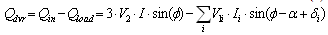
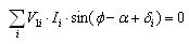
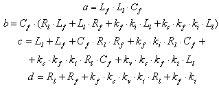
 δ and α represent the load current, load power factor angle, supply voltage phase angle, and load voltage advance angle, respectively. Unlike the in-phase voltage injection technique, the proposed PAC technique is realized by the adjustment in α. One distinct advantage of the proposed scheme is that less real power is needed to be injected from the DVR energy storage unit into the distribution system[2,18,19]. Assume that the load has an inductance Ll , a resistance Rl , and the DVR harmonic filter has an inductance Lf , a resistance Rf , and a capacitance Cf. The DVR injection transformer has a combined winding resistance Rt and a inductance Lt. Consider the power flow contributions of the DVR under the PAC scheme. If Pin and Pload are the input power from the source and the load power respectively, and similarly, if Qin and Qload are the input reactive power from the source and load reactive power respectively, then
  | (1) |
 | (2) |
 | (3) |
 | (4) |
 | (5) |
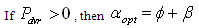
 .Else if
  then
then 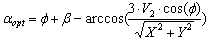 | (6) |
 | Figure 1. Schematic of a power distribution system compensated by a DVR |
 | Figure 2. Phasor diagram of power distribution system during a sag |
3. Comparison of In-Phase Injection with PAC
- In this section single-phase, two-phase, and three-phase voltage sags are simulated with mentioned power injection equations. Consider the typical system arrangement as shown in Fig.1 where the sensitive load is assumed to have a power factor of 0.8 lag and the presag load voltage and current are at 1 p.u. The voltage sags for three cases are 10-70%. Fig.3. shows the relationship between the real power supplied by the DVR and the corresponding phase advance angle α. In case (a), it can be seen that the power required for in-phase injection (α = 0) and 30% sag is 0.08 p.u. and this decreases with the advance in α. Negative DVR real power means that the DVR absorbs the power from the line which is undesirable. In case (a) for 30% sag the DVR required 0.06 p.u. reactive power for in-phase injection and this increases with the α.For cases (b) and (c) it can be seen that the DVR can control the load voltage without supplying any real power to the load for a balanced sag level of up to 0.2 p.u. Based on the above analysis , the amount of storage energy can be reduced, thus resulting in a more economical restorer in terms of a more compact design and it is possible to ride through some sags without the need to supply energy from the DVR. Therefore, the sag duration is not an important issue for this type of sag, while it can be extremely critical for the in-phase boosting technique. But with PAC, magnitude of the injected voltage is larger than that of based on in-phase injection method and as the phase advancement angle needs to be determined in real time, the control system is more complex.
4. DVR Inverter Modeling and Control System Design
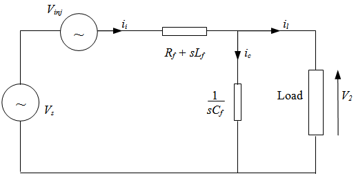
- In the presence of semiconductor switches in the inverter bridge, the DVR inverter model is non-linear. However it is possible to describe the DVR behaviour in differential or difference form using the state space averaging technique. The dynamic characteristics of the inverter are mainly governed by the LC filter and connected load[4, 9, 10]. The connected load can either be linear static, non-linear, dynamic or their combination. Modeling of a non-linear load may require a different approach. In this study the load is assumed to be linear RL type with an added disturbance to represent load dynamics. By modeling the load in this manner, it is possible to observe the controller behaviour due to the dynamic changes in the load. The equivalent single line diagram of the DVR inverter is shown in Fig.4 where negligible line impedance between the DVR and the supply voltage bus bar (point of common coupling) is assumed. Using this diagram the following expression can be derived in state space form.
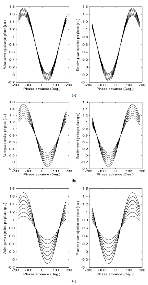 | Figure 3. Active and reactive power injected from DVR versus phase advance α for: (a) single phase voltage sags; (b) two phase voltage sags; (c) three phase voltage sags |
 | Figure 4. Equivalent circuit of the DVR inverter |
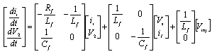 | (7) |
 .The transfer function between load voltage and input reference is expressed as follows
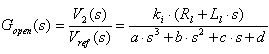 | (8) |
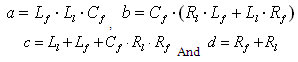 .Using Routh-Hurwitz stability criteria it can be shown that the system is inherently stable for all possible values of system parameters. One root is a real root and is approximately located at –Rl /Ll and real parts of other two dominant complex roots are given by –Rf /2Lf. Therefore the damping of the system is governed by filter resistance Rf. Increasing the filter resistance to improve damping and to control overshoot at the instant that DVR begins its operation may lead to other problems such as increasing power loss, introduction of a phase angle between the inverter and filter outputs and filter voltage drop[20,21]. Therefore an increasing in the filter resistance may not be beneficial in view of system efficiency and accuracy. One of the essential requirements of the DVR controller is its ability to correct the load voltage towards its desired level. Required injected voltage is achieved by appropriately controlling the inverter output voltage[22, 23]. The inner current loop can be formed using filter inductor current, filter capacitor current or combination of the two currents. The following sections present those controller options with a comparative analysis of their merits and limitations.
4.1. Closed-Loop Controller with Filter Inductor Current Feedback
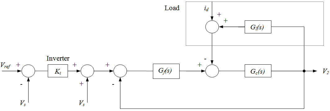
- In this control option, inner loop is formed using filter inductor current and there is also a feed forward loop consisting of difference between the reference voltage and the input supply voltage. This loop intends to enhance dynamic performance in terms of response time and steady state error. The controller block diagram is shown in Fig.6. Transfer function is
 | (9) |
 .
.4.2. Controller with Capacitor Current Feedback
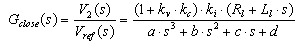
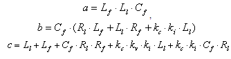
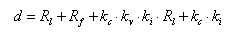
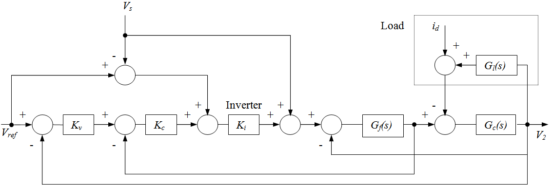
- The block diagram of this control system is similar to that of shown in Fig.6 except that the current feedback is taken from the capacitor current ic. The transfer function between load voltage and input voltage reference is
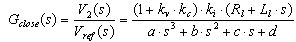 | (10) |
 | Figure 5. Open loop controller block diagram of the DVR inverter |
 | Figure 6. Closed loop control system with inductor current feedback |
 | Figure 7. Multi-loop feedback controller block diagram for voltage regulation |
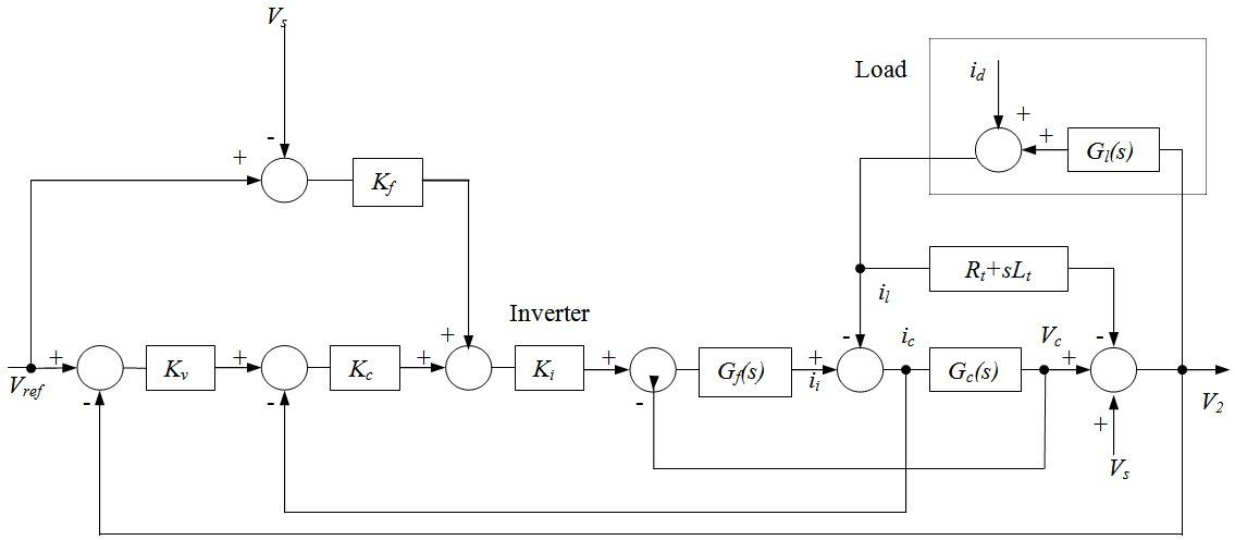
4.3. Closed-Loop Controller with Combination of Capacitor and Inductor Current Feedback
- As the load current has direct relationship with the inductor current, if a portion of the inductor current is added to the capacitor current feedback, the system performance can be further improved. This can be verified by deriving the transfer functions between the load voltage and input voltage reference. The transfer function is
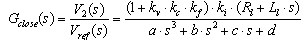 | (11) |
 .
.5. Simulation Results
- A detailed simulation of the proposed DVR control system has been carried out using MATLAB software. The system parameters are given in the Appendix.
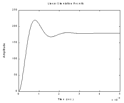
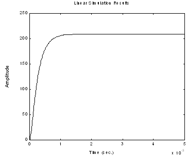
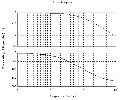
5.1. Controller with Inductor Current Feedback
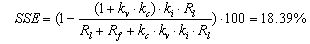
- For a step input, the steady state error between the reference voltage and the load voltage can be expressed as
 | (12) |
 | Figure 8. Step response of controller with inductor current feedback |
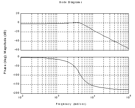
 | Figure 9. Bode diagram of controller with inductor current feedback |
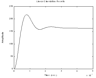
5.2. Controller with Capacitor Current Feedback
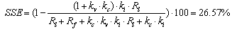
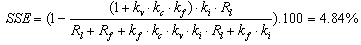
- For a step input, the steady state error between the reference voltage and the load voltage is
 | (13) |
 | Figure 10. Step response of controller with capacitor current feedback |
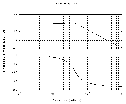
 | Figure 11. Bode diagram of controller with capacitor current feedback |
5.3. Controller with Combination of Capacitor and Inductor Current Feedback
- For a step input, the steady state error can be expressed as
 | (14) |
 | Figure 12. Step response of controller with combination of capacitor and inductor current feedback |
 | Figure 13. Bode diagram of controller with combination of capacitor and inductor current feedback |
6. Conclusions
- A new phase advanced multi-loop control scheme has been proposed for the dynamic voltage restorer. Through analysis simulation, it is shown that the proposed scheme is superior compared to the conventional in-phase injection technique in terms of energy saving and dynamic performance. Such characteristics are highly desirable as the design is seen to lead in a more economical restorer which can improve the ride-through capability of sensitive loads and industrial processes. The analysis has shown that the DVR has poor dynamic performance and low stability margin when it is operated with the open loop controller. The closed-loop control scheme with an inner current loop and outer voltage loop has increased the quality of load voltage by improving the damping, stability and the dynamic performance. Theoretical analysis has proven that the capacitor current feedback scheme is superior over the inductor current feedback scheme in terms of steady state error and disturbance rejection. Controller robustness to load variations can further be improved by taking a combination of inductor and capacitor current feedback loops into the inner current loop.
Appendix
- System parameters are :Supply voltage(rms) : 220 VFilter inductance : 5 mHFilter resistance : 0.4 ΩFilter capacitance : 30μFLoad inductance : 114 mHLoad resistance : 57 Ωkv = 0.1, kc = 35, ki = 0.5, kf = 6