-
Paper Information
- Paper Submission
-
Journal Information
- About This Journal
- Editorial Board
- Current Issue
- Archive
- Author Guidelines
- Contact Us
Computer Science and Engineering
p-ISSN: 2163-1484 e-ISSN: 2163-1492
2025; 15(1): 14-21
doi:10.5923/j.computer.20251501.02
Received: Jan. 7, 2025; Accepted: Feb. 2, 2025; Published: Feb. 26, 2025

Resilient IP Network Architectures: Innovative Methods for Congestion Mitigation During Unplanned Failures
 Abstract
 Reference
 Full-Text PDF
 Full-text HTML
Simon Tembo1, Ken-Ichi Yukimatsu2, Ryota Takahashi2, Shohei Kamamura3
1Department of Electrical and Electronic Engineering, University of Zambia, Lusaka, Zambia
2Department of Computer Science and Engineering, Akita University, Akita-shi, Akita, Japan
3Department of Computer Science, Seikei University, Musashino-shi, Tokyo, Japan
Correspondence to: Simon Tembo, Department of Electrical and Electronic Engineering, University of Zambia, Lusaka, Zambia.
| Email: |  |
Copyright © 2025 The Author(s). Published by Scientific & Academic Publishing.
This work is licensed under the Creative Commons Attribution International License (CC BY).
http://creativecommons.org/licenses/by/4.0/

Research has identified significant shortcomings in modern IP backbone networks, with approximately 20% of failures occurring during scheduled maintenance and the remaining 80% arising unexpectedly. To mitigate service disruption, IP Fast Reroute (IPFRR) minimizes recovery time by precomputing backup routes that enable immediate traffic redirection in the event of a failure. Among IPFRR techniques, the Multiple Routing Configurations (MRC) scheme generates backup topologies to guide rerouting; however, scaling MRC often results in excessive resource usage, including increased demands on forwarding table space and link-state messaging. Simplifying MRC by reducing backup topologies can lead to link congestion, especially under high-traffic conditions. This paper introduces an innovative backup topology design algorithm that addresses congestion during unplanned failures. The proposed method leverages Special Nodes—nodes characterized by high connectivity (node degree) within the backup topology—to redistribute traffic from overloaded links to alternative paths. Considering critical network conditions such as traffic matrices and topological structure, the algorithm achieves efficient load balancing across the network. Experimental evaluations show that the maximum link load can be brought down to roughly a quarter of what traditional methods experience—even though both strategies employ the same number of backup topologies, which underscore this solution’s scalability across any network size. Its effectiveness is especially pronounced in large-scale environments, where designating a select subset of nodes (around one out of every five) based on strategic considerations minimizes congestion and significantly strengthens overall network resilience.
Keywords: Unplanned Failures, IPFRR, Backup Topologies, Congestion Prevention, Traffic Splitting, Special Nodes
Cite this paper: Simon Tembo, Ken-Ichi Yukimatsu, Ryota Takahashi, Shohei Kamamura, Resilient IP Network Architectures: Innovative Methods for Congestion Mitigation During Unplanned Failures, Computer Science and Engineering, Vol. 15 No. 1, 2025, pp. 14-21. doi: 10.5923/j.computer.20251501.02.
Article Outline
1. Introduction
- Modern IP backbone networks are prone to failures that significantly impact their reliability and availability. Research findings in [7] reveal that approximately 20% of network failures occur during scheduled maintenance activities, while the remaining 80% are unplanned. Among these unplanned failures, 30% involve multiple links, often due to issues with routers and optical equipment, whereas 70% affect only a single link. To address these challenges, IP Fast Reroute (IP FRR) methods have been extensively studied for achieving rapid failure recovery, often within a few milliseconds. IP FRR enhances network resilience by precomputing backup routes that reroute traffic immediately after a failure, bypassing the delays associated with routing convergence [1-6], as illustrated in Figure 1. However, a critical limitation arises when rerouted traffic overloads backup routes, leading to congestion unless traffic is carefully distributed based on available capacity [26,28-29]. To mitigate congestion, the Multiple Routing Configurations (MRC) method [2] has been proposed, which precomputes multiple backup topologies [5-6] to ensure packet delivery under various failure scenarios.
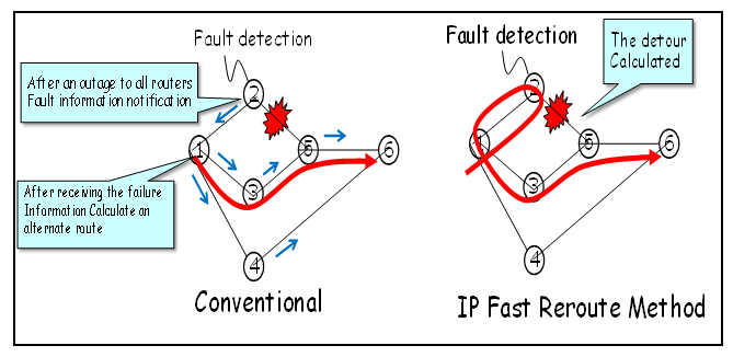 | Figure 1. Traditional IP Network versus IP Fast Reroute Network |
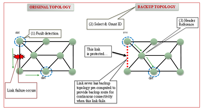 | Figure 2. Original Topology with Backup Topology [5,6] |
2. Related Works and Problem Statement
- In this section, we outline the features of backup configurations employed in the MRC method [3] and highlight the challenges associated with this approach. Subsequently, we present a novel backup topology design mechanism that mitigates congestion during unplanned failures by leveraging optimized backup topologies.
2.1. Characteristics of Backup Configurations
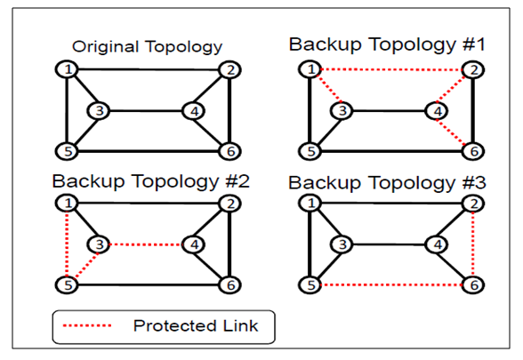
- IP Fast Reroute can be achieved by leveraging pre-computed backup topologies, as outlined in [2]. In this approach, backup topologies are calculated in advance and deployed across all routers in the network. Each backup topology is characterized by a unique set of link metrics, enabling routers to determine the shortest paths and configure routing entries not only for the primary topology but also for the alternative backup topologies. When a link failure occurs, the affected router identifies the backup topology that circumvents the failed link and encodes its identifier into the IP header’s Type of Service (TOS) field. The packets are then forwarded to the next hop based on the routing information of the chosen backup topology, and subsequent routers use the TOS field to consistently maintain the packet's trajectory along the designated alternate path.In a backup topology, certain links—termed protected links—are intentionally set aside so that they do not carry traffic in the event of a failure [5-6]. Backup routes are then established exclusively using the remaining links that are not designated as protected. To guarantee that the network can recover from any single link failure, the following conditions must be satisfied:1. Every link within the network must be assigned as a protected link in at least one backup topology.2. Each backup topology must form a connected graph that deliberately omits its designated protected links.By adhering to these criteria, the system ensures that for any potential link failure, there is always at least one backup topology available to effectively reroute traffic around the problematic link [5-6].
2.2. Overview of Fast Reroute Using Backup Topology
- Effective failure recovery in IP networks is critical for maintaining robustness and delivering high-quality service. The core challenge is to achieve swift recovery without incurring excessive complexity or resource overhead. Traditional recovery strategies generally fall into two categories: route recalculation and lower-layer protection. Route recalculation methods, however, often introduce delays of several seconds, while lower-layer protection—such as that implemented in IP Fast Reroute (IPFRR) systems—necessitates the reservation of redundant bandwidth.IPFRR overcomes these limitations by equipping routers with supplementary routing information, enabling them to immediately forward packets along alternative paths as soon as a failure is detected [1–5], [10–11], [14–27]. In this scheme, routers maintain several Forwarding Information Bases (FIBs): a. one for the original network topology and b. others for various backup topologies. When a packet arrives, the router determines which FIB to consult by using a key that combines the failure identifier with the destination IP address and then directs the packet to the next-hop node specified in the selected FIB. For example, consider the scenario depicted in Figure 3. When node 1 detects a failure on link 1-2 while transmitting packets destined for node 2, it immediately switches to backup configuration #1—a topology specifically designed to mitigate the impact of this failure. In this backup mode, node 1 uses the TOS field to route packets to nodes 5, 6, and 2. Importantly, the failure identifier is appended only to those packets that would have otherwise been sent over the compromised link, while all other traffic continues to be forwarded according to the original topology [5-6].
 | Figure 3. Overview of the Backup System Architecture [5-6] |
2.3. Problem Statement
- Our backup topology design approach focuses on maintaining balanced link loads after a network failure, with a particular emphasis on IP fast reroute. In such a topology, a subset of links is pre-assigned as protected, which limits the number of links available for rerouting traffic during failures. This limitation forces the recovered traffic to concentrate on a small number of backup links, often resulting in overloading. Such overloaded links can lead to increased network congestion, ultimately degrading the overall quality of service.Figure 4(a) demonstrates that the conventional IP fast failure recovery method described in [2] inadvertently causes link 5-7 to become overloaded. This bottleneck occurs because traffic from source nodes 1, 3, and 6 destined for node 7 is routed exclusively via link 5-7—the only link lacking protection. With links 4-7, 6-7, and 7-8 already safeguarded and unavailable for rerouting, the concentration of traffic on link 5-7 results in significant congestion, ultimately degrading network performance [5,6].
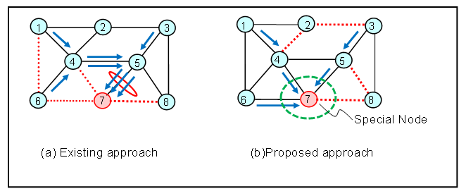 | Figure 4. (a) Congestion challenges in the existing approach.. (b) Our approach using a Special Node to redistribute hotspot traffic [5,6] |
3. Algorithm for Congestion Mitigation
3.1. Overview
- At the heart of our algorithm lies the strategic selection of a Special Node within the backup topology. This node is chosen based on vital network parameters—such as the traffic matrix or the overall topology—which guide its determination. Depending on the specific network conditions at play, we adopt one of two strategies to designate this Special Node: either through the Load Order method or the Degree Order method.
3.2. Special Node Selection Approaches
- 1. Load Order Method:This approach identifies the Special Node based on a detailed traffic matrix. The algorithm begins by calculating the total traffic for each node, summing both incoming and outgoing flows. The node with the highest overall traffic is then selected as the Special Node. As this method depends on the availability of comprehensive traffic data, it requires a complete traffic matrix for accurate computation.2. Degree Order Method:In contrast, the Degree Order Method determines the Special Node through an analysis of the network's topology. Here, the focus is on the node degree, which is defined as the number of links connected to a node. The algorithm computes the degree for every node and designates the node with the highest degree as the Special Node. This method relies solely on structural information and does not require any traffic data.Both methods offer distinct criteria for node selection—one based on dynamic traffic metrics and the other on static network structure—thereby providing complementary perspectives for identifying key nodes within a network. To demonstrate the selection of Special Node, we have used the simulation of the HLDA topology (Figure 5) [9] and its given traffic matrix. Figures 6 and 7 illustrates the selected Special Nodes using the Load Order and Degree Order methods. In both cases Node 2 is the Special Node.
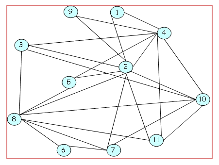 | Figure 5. Hierarchical Load Distribution Architecture (HLDA) [9] |
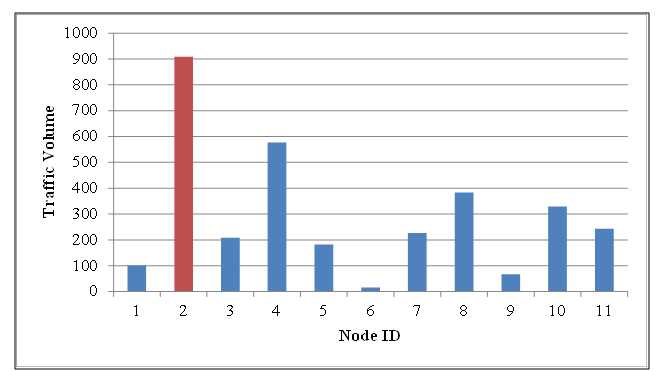 | Figure 6. Selecting Special Nodes using Load Order for HLDA Topology |
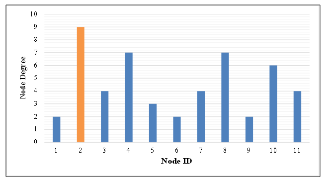 | Figure 7. Selecting Special Nodes using Degree Order - HLDA Topology |
3.3. Algorithm
- Figure 8 outlines the flow diagram of our algorithm. It takes the network topology as input along with an optional traffic matrix. The primary input parameter is the number of Special Nodes (K), and the algorithm outputs the number of backup topologies (N). Initially, N is set to one, and then the algorithm proceeds by continuously iterating through Steps 1 to 4. Below outlines a four‐step algorithm for selecting Special Nodes and designing backup topologies to protect network links:
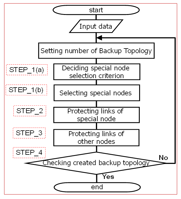 | Figure 8. Flow Diagram for the Proposed Algorithm [5,6] |
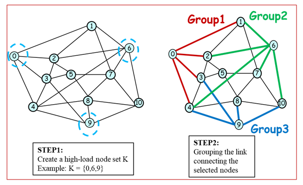 | Figure 9. Steps 1 & 2 for Special Nodes Selection for Proposed Algorithm |
4. Performance Evaluation
- In this section, we quantitatively evaluate the effectiveness of the proposed methods by measuring the link load following a potential single link failure.
4.1. Simulations Conditions
- In our simulation, we use HLDA [9] (optimum model), COST239 [10] (actual European model) and COST266 [11] (actual European model), as network topology models as shown in Figures 10 and 11. The routing algorithm is assumed to be a minimum cost routing. We use a gravity model type of traffic demand according to the population distribution.
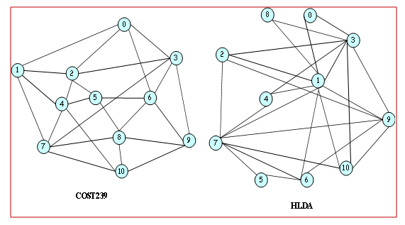 | Figure 10. COST239(11 Nodes, 25 Links) & HLDA(11 Nodes, 25 Links) |
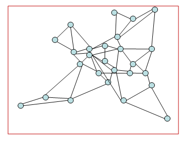 | Figure 11. COST266 (26 Nodes, 49 Links) |
4.2. Results and Discussion
4.2.1. Results Analysis Considering Traffic Volume
- Figure 12 illustrates the correlation between node degree and traffic volume, which helps explain the varying effectiveness of the Degree Order method when applied to different models. For the HLDA model, the node degree shows a strong positive correlation with traffic volume, making the Degree Order method, which relies on node degree, more effective in reducing load. In contrast, the COST239 model exhibits a weaker correlation between node degree and traffic volume, resulting in less effective load reduction when using the Degree Order method. This highlights the model-specific dependency of the Degree Order approach, with HLDA benefiting from this method due to its higher correlation, while COST239 does not. The evaluation results, depicted in Figure 13, highlight the impact of traffic volume on the load reduction performance of our congestion mitigation algorithm applied to HLDA and COST239 topologies. Using the traditional method (with backup topologies of N=3, With NO Special Nodes, i.e. K = 0), we observed traffic concentration on certain links. However, employing the Load Order and Degree Order methods (with backup topologies of N=3, and with Special Nodes of K=3) for IP fast failure recovery resulted in improved load reduction. The Load Order method achieved a 75% reduction in load for COST239 and 73% for HLDA, while the Degree Order method led to a 53% reduction for COST239 and 73% for HLDA. The results in Figure 9 demonstrate that the Load Order method effectively reduces high link load. Specifically, in the COST239 network model, selecting high-load nodes as Special Nodes enhances load reduction. The Load Order method’s effectiveness improves for COST239 due to the choice of higher-load nodes, whereas the Degree Order method shows minimal improvement. In contrast, for HLDA, the load reduction performance of both Load Order and Degree Order methods remains unchanged, regardless of the selection method.
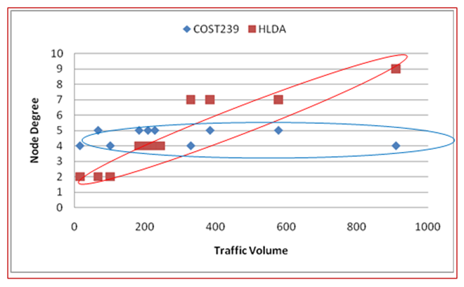 | Figure 12. Correlation between Node Degree and Traffic Volume for COST239 and HLDA network models [5,6] |
 | Figure 13. A Comparative Analysis of Load Reduction in COST239 and HLDA [5,6] |
4.2.2. Results Analysis Considering Node Position
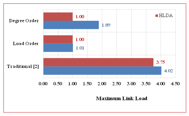
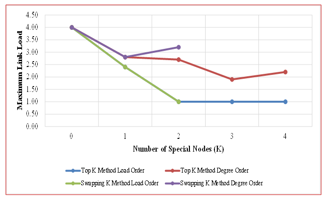
- Figures 14 and 15 compare three approaches for selecting Special Nodes in backup topologies—Load Order, Degree Order, and a Traditional method (K=0, meaning no Special Nodes)—using the COST239 and COST266 network models. The performance metric of interest is the minimum value of the maximum link load.
 | Figure 14. Top K & Swapping K Methods Applied to the COST239 |
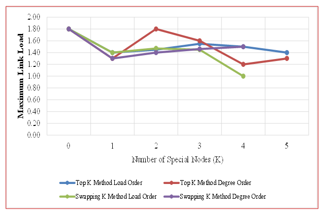 | Figure 15. Top K & Swapping K Methods Applied to the COST266 |
4.2.3. Comparative Analysis
- In the larger COST266 network (Figure 15), the Load Order method only surpasses the Degree Order method when node positions are explicitly considered through the Swapping K technique. In contrast, under the Top K method, the Degree Order approach achieves a lower maximum link load is 1.2 (at K=4) than the Load Order approach is 1.4 (at K=5). Furthermore, because the COST266 model includes more nodes than the COST239 model, the likelihood of choosing adjacent nodes as Special Nodes increases considerably.Selecting adjacent nodes as Special Nodes in the Load Order method fails to maximize the number of accessible links, resulting in a higher minimum value for the maximum link load compared to the Degree Order approach (see Figure 15 at K=5). This reduced effectiveness is influenced by the network’s structure and the nature of its traffic matrix, and it can remain suboptimal if node position is not considered. However, when node position is considered through the Swapping K technique, the Load Order method outperforms the Degree Order method (see Figure 15 at K=4). Notably, while the Degree Order method achieves a minimum maximum link load of 1.3 at K=1, the Load Order method lowers it to 1.0 at K=4. From these findings, we conclude that in larger networks, incorporating node position when choosing Special Nodes for the Load Order method is a valuable strategy. The results indicate that the optimal reduction in link load occurs when Special Nodes constitute approximately 20% of the total nodes in a network topology. In the COST239 model, the maximum reduction effect was observed at K = 2 (Figure 14), whereas in the COST266 model, the best reduction effect was achieved at K = 4 (Figure 15).
4.2.4. Scalability Analysis
- In IP Fast Reroute, backup routes are precomputed using backup topologies to minimize service disruption during failures. The existing approach prepares these topologies in advance, determining backup routes after a failure. However, increasing the number of backup topologies consumes significant network resources, as it directly impacts the size of router forwarding tables and the volume of link-state messages. To enhance scalability, a refined approach, in this paper has been introduced to reduce the number of backup topologies, thereby lowering memory load on routers [3-6]. However, fewer backup topologies can lead to link overload. To mitigate this, selecting approximately 20% of nodes as special nodes, with strategic positioning in large networks, has proven effective in optimizing performance.
4.2.5. Implementation Challenges
- However, in each network configuration, if the number of special nodes K is increased further, the integrity of the backup topology without protected links cannot be preserved—failing to meet the backup topology's requirements. Raising K past these ideal points results in a disconnection of the backup topology due to the omission of protected links. The highest feasible K corresponds to the point where connectivity remains intact, indicated by the furthest right data point on the graph. While theoretically, a higher K might provoke competition among Special Nodes and heighten link load, the network loses connectivity before such dynamics emerge. Particularly in extensive networks, the selection of a Special Node should strategically consider node placement to maximize effectiveness; special nodes must not be adjacent. Thus, it is vital to determine the highest practical K value that sustains connectivity without surpassing this limit.
5. Related Works
- In modern communication networks, failure recovery mechanisms are essential to maintain reachability, scalability, support for multiple simultaneous failures, and congestion avoidance on detour paths. Existing IP Fast Reroute (IPFRR) techniques, widely explored in the literature, can achieve traffic restoration within a few milliseconds [1–6], [12–13], [16–23]. To ensure scalability, a backup topology design approach is needed to reduce the number of backup topologies and, consequently, the memory load on routers [3–4]. For recovering from multiple simultaneous failures, researchers have proposed both a backup topology design algorithm and extensions to the forwarding mechanism [12]. Additionally, Kvalbein et al. [13] introduced a link load balancing method based on route optimization [14], aiming to mitigate congestion through optimized backup topologies.In IP networks, route optimization translates to optimizing link metrics because IP routing decisions are determined by link costs. The fundamental principle of link metric optimization [14] is to maximize traffic distribution by creating multiple routes between source and destination nodes, referred to as Equal Cost Multi-Paths (ECMPs) [8,15]. In [12], the authors first constructed a backup topology following the procedure outlined in [2] and then applied link metric optimization [12] to the unprotected links. However, a limitation of the approach in [13] is that its backup topologies sometimes lack sufficient path diversity. As illustrated in Figure 4(a), the lack of diverse paths to node 7 can lead to congestion. Hence, if a backup topology does not offer enough alternative paths, congestion remains an issue [2]. This phenomenon is further validated in our simulation results (Figures 13, 14–15).While the route optimization framework used in [2] can be effective, the resulting backup topologies often restrict the set of available links, which compromises path diversity for reachability. As a result, it does not fully resolve the congestion mitigation challenge because too few links are available in a single backup topology.
6. Conclusions
- In this paper, we introduce a backup topology design method aimed at minimizing congestion and ensuring efficient IP fast restoration. Through extensive simulations, we show that our approach outperforms the conventional method [2] by reducing congestion by up to 75%—all while using the same number of backup topologies.A key innovation lies in the introduction of Special Nodes, comprising about 20% of all nodes. By carefully selecting these Special Nodes—particularly high-load nodes located in strategic positions—we can significantly lower link loads during failures. In smaller networks, such as COST239 and HLDA, choosing Special Nodes based on the Load Order (high-load nodes) yields a 75% congestion reduction in COST239 and 73% in HLDA. The Degree Order (high-degree nodes) strategy also performs well but can be slightly less effective, depending on network structure and traffic patterns.In larger networks like COST266, both the network topology and the traffic matrix shape the method’s effectiveness. Our results reveal that paying attention to node position is especially critical when selecting high-load nodes for the Load Order approach; doing so enhances performance more than the Degree Order method.In summary, our backup topology method benefits from:1. Introducing Special Nodes to minimize congestion.2. Adapting node selection strategies (Load Order or Degree Order) based on network size and topology.3. Considering node position in larger networks to maximize congestion reduction.For future work, we are combining the backup topology design with route optimization method to further reduce the number of backup topologies and overall network traffic.