-
Paper Information
- Paper Submission
-
Journal Information
- About This Journal
- Editorial Board
- Current Issue
- Archive
- Author Guidelines
- Contact Us
Computer Science and Engineering
p-ISSN: 2163-1484 e-ISSN: 2163-1492
2018; 8(2): 17-22
doi:10.5923/j.computer.20180802.01

Automatic Detection System to the Sticky Bomb
 Abstract
 Reference
 Full-Text PDF
 Full-text HTML
Raed Majeed1, Hiyam Hatem2, Muhanad Mohammed3
1Department of Computer Information Technology, Collage of Computer Science and Information Technology, University of Sumer, Iraq
2Department of Computer Science, Collage of Computer Science and Information Technology, University of Sumer, Iraq
3Collage of Science and Mathematics, University of Thi-Qar, Iraq
Correspondence to: Raed Majeed, Department of Computer Information Technology, Collage of Computer Science and Information Technology, University of Sumer, Iraq.
| Email: |  |
Copyright © 2018 The Author(s). Published by Scientific & Academic Publishing.
This work is licensed under the Creative Commons Attribution International License (CC BY).
http://creativecommons.org/licenses/by/4.0/

The detection of explosives has become an important area in recent years for preventing terrorist activities, particularly in areas away from static checkpoints. Day by day, terrorism is becoming increasingly dangerous and threatens the lives of individuals, new technology approaches are needed for tighter security rises. One of the most common terrorist activities is sticky bomb (an explosive device that affixed to a vehicle either by magnetism or an adhesive). A diversity of Under-Vehicle Inspection System (UVIS) presented to detect such threats. UVIS needed at border customs stations, airports, embassies, sporting events, etc. In this paper, we present a mobile UVIS, an efficient and moderate cost sticky bomb detection system that enables individuals to examine their vehicle from explosive material, while maintaining the security of the vehicle owner.
Keywords: Under-Vehicle Inspection System (UVIS), Panoramic Image Recognition, 3D Image Reconstruction, Principle of Triangulation
Cite this paper: Raed Majeed, Hiyam Hatem, Muhanad Mohammed, Automatic Detection System to the Sticky Bomb, Computer Science and Engineering, Vol. 8 No. 2, 2018, pp. 17-22. doi: 10.5923/j.computer.20180802.01.
Article Outline
1. Introduction
- Probably the most criminal activities of terrorism are sticky bombs. In which individuals targeted by pasting explosive devices in their vehicles and detonated by timer or through remote control. An under-vehicle inspection system UVIS is used to discover threats likes explosive materials which are unobserved under the vehicles. Usually a photographic device used to captures images for the underneath vehicle for manual or computerized persona inspection. The practice of inspecting the under-vehicles is not new. It starts at the height of the Cold War, where East German border patrols used inspection mirrors to check for weapons. They applications are limited and place security personnel in close proximity to potential danger. images and video technologies provide security personnel a very well defined overview of the vehicle’s undercarriage from a safer position while protecting them life form danger [1].The digital technology is growing more complex, with the addition of LED and infrared lighting, motion-activated imaging sensors and network capabilities. The most important key variables we consider related to UVIS are:Ÿ Total cost of ownership: The main purpose of this research is to introduce a low cost system than can be owned by vehicle owner. Ÿ Image clarity: One of the major Services from using UVIS system is to indicate the shape, location and dimension of the object attached to the vehicle. Than involve other image processing tools like: (zooming, filtering, segmentation, etc.). The more cleared image we get, the better UVIS we have. Ÿ Processing Speed: the most important and critical fundamental different between the UVIS technologies is the time required to finish all the activity of such systems and present images to the security examiner.Ÿ Usability: its refer to level of comfortable that person feel while using new UVIS technology, no matter how good the system performs and its efficient rather than the cost saving it can offer. Ÿ Risk Management: The Main challenge is; It represents the ability to control the security strategies while been maintain the threat detection to minimize the impacts on persons we serve.The paper is organized as follows. Section 1.1 describes how the general UVIS system works referring to the important factors related to the design. Section 1.2 gives an overview of the improvised explosive device (IED). Section 2 is a survey of the existing hardware and software systems available for under vehicle inspection, highlighting the drawbacks for each technique, Section 3 gives an overview of the hardware requirements for the proposed under vehicle inspection system. Section 4 presents our inspection system and the development of the hardware and software designs, respectively. Finally, we present concludes with closing remarks.
1.1. Structure of UVIS System
- The general working mechanism for UVIS can be summarized as: the vehicle achieve at the inspection area and go over the imaging unit, and then it snapshot multiple image from different angles to the vehicle undercarriage, then forward the captured images to the control unit which show them for examiner. Depending on the UVIS system design, the control unit and can be placed outside or inside the inspection area., images of the vehicle’s undercarriage can be stored for later viewing or can be manipulated for closer inspection while the vehicle is detained, figure 1.
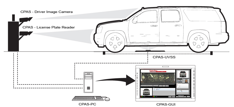 | Figure 1. Basic UVIS design |
1.2. Improvised Explosive Device (IED)
- An improvised explosive device (IED) refer to a bomb constructed in ways other than in conventional military action. like artillery round, attached to a detonating mechanism It can be constructed of conventional military explosives. IEDs are commonly used as roadside bombs. An IED consist of five parts: a switch (activator), an initiator (fuse), container (body), charge (explosive), and a power source (battery). Antipersonnel IEDs typically also contain fragmentation-generating objects such as nails, even small rocks to cause wounds at greater distances than blast pressure alone could [3]. IEDs are triggered by various methods, including remote control, infrared or magnetic triggers, pressure-sensitive bars or trip wires (victim-operated). An IED designed for use against armoured targets such as personnel carriers or tanks will be designed for armour penetration, by using a shaped charge that creates an explosively formed penetrator. IEDs are extremely diverse in design, and may contain many types of initiators, detonators, penetrators, and explosive loads. IEDs are generally seen in heavy terrorist actions or in unconventional warfare by guerrillas or commando forces in a theater of operations. In the second Iraq War, IEDs were used extensively against US-led invasion forces and by the end of 2007 they had become responsible for approximately 63% of coalition deaths in Iraq [3].Magnitude of varied extemporary bombard movables (IEDs) at standoff distances of 20, 30 and 55 m were unabated in tyrannical mood issuing from snow to sun and temperatures ranging from 22°C to −8°C. The set-up, beyond a 532 nm pulsed laser creation, was kept leading a laboratory far the analyse and the radiate down wide onto an explosives correct scrutiny section close to the laboratory, thereby allowing the samples to be placed outdoors in an open environment. [4]One of the new realities is a heightened awareness of the types of threats that now exist. According to figures from [5] the Global Database on Terrorism, see Figure 2, from 1970-2011, explosive devices have topped the list. Given the number of attacks on U.S. troops involving improvised explosive devices (IEDs), the threat of vehicle-borne IEDs (VBIED) have received significant attention. Concern over VBIEDs, as well as an increase in contraband attempting to cross the U.S. border, has created the need for more advanced under-vehicle inspection systems (UVIS).
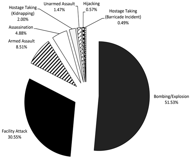 | Figure 2. Methods of terrorist attacks on U.S. (1970-2011) |
2. Literature Review
- This section gives a survey of the existing systems available for under vehicle inspection referring to the main points of strength and weakness. Other systems are technically based on these detection techniques. Almost all currently available inspection systems are based on an inspector manipulating a convex mirror under a vehicle [6, 7]. Uses a pole with a pan/tilt camera head at the end introduced in [8], the system also has a zoom capability, and the pole can be articulated to a maximum of 160 degrees. A static, fixed camera is placed in the path of the vehicle, the camera is arranged horizontally viewing the vehicle directly when it crosses the system in [9]. Uses a portable system that has a waterproof camera and lighting modules in [10], the system must be placed anywhere in the vehicle path and is able to capture high resolution images. [11] Uses digital line scan technology for under vehicle inspection, there are two versions of this system are available, mobile and static systems. The system scans under the vehicle in few seconds and is available in touch screen for visualization and zooming.
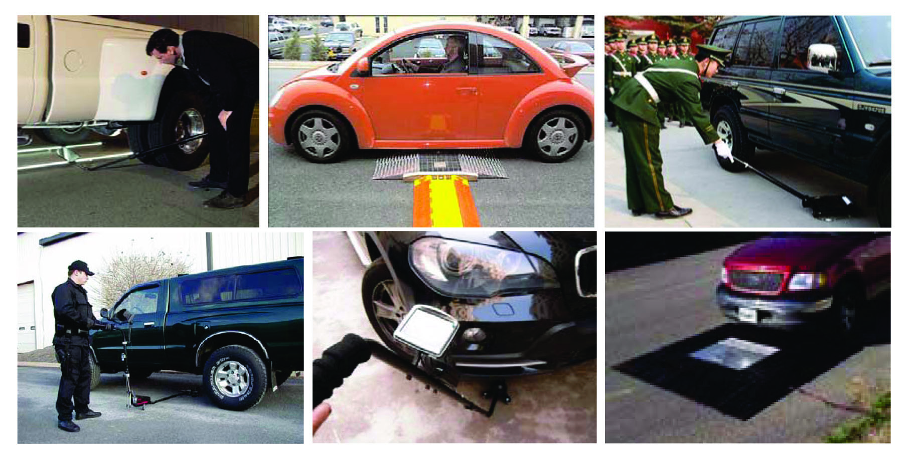 | Figure 3. Currently available inspection systems |
2.1. Drawbacks of Existing Detection Techniques
- There are many drawbacks exists in the UVIS systems we are noted the most common, Using mirrors is both time-consuming and labour-intensive, generality mirrors supply a finited view of the under vehicle, unsuccessful, show screeners key areas by the medium of the vehicle. In tire pressure method the: (noise, weather pressure, temperature changes, etc.) could change the reading results of sensitive instrument involved. The rare earth magnet detection is an efficient method yet it cannot detect a bomb that uses adhesive, fast penetrating screws, straps, zip ties or putting the bomb in a cavity under the car. Most of other UVIS fail to deal with the reason of present our system, where, an individual need to check his vehicle (personal use). Using Dogs also has their own drawbacks since they are living beings, they need caring, feeding and cannot be used personally.
3. System Hardware Requirements
- The proposed system consists following main hardware components: see figure 4. 3.1. Camera with high-intensity bright white LEDs for night vision.3.2. Moving arm attached to the body of the vehicle.3.3. Red Laser Diode Line Module Board Focus Adjustable Laser Head Unit.
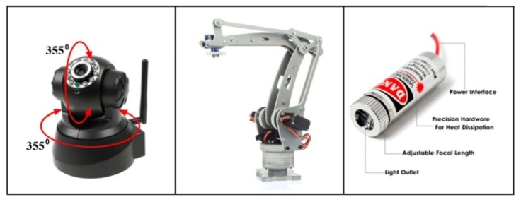 | Figure 4. Presented system hardware components |
3.1. Night Vision Webcam
- The Camera Specifications listed as below:• Support different types of network connection methods: TCP/IP, HTTP, ICMP, DHCP, FTP, SMTP, PPPOE etc.• CMOS 300,000 pixel. Support M-JPEG Compression format Video.• (5x10) IR-LED, spontaneous works for night vision (Up to 10 meters).• Allow remote viewing & record from anywhere anytime. High image & video quality. Simple and quick to setup, friendly user interface.
3.2. Four-Axis Robot Arm
- The moving arm adopted in our system has the following Features and Controller Specifications:• Emulate genuine palletizing robot arm construction. PVC material, CNC processing.• Digital I/O port 0~13 or Analog I/O port 0~5.• Adopts USB interface protocol and power supply.• Adopts (single chip TX/RX, USB to TTL TX/RX, AREF, 6 PWM) circuits.• Input voltage: USB power supply or external 7-12V DC input.• Output voltage: 5V DC output/3.3V DC and external power input.• Support MG995 55g metal gear servo 3pcs. Vigorous common bearing connection.
3.3. The Laser Diodes
- Red Laser Diodes Line Module Board Focus Adjustable Laser Head Unit 5V Lasermodul Industrial Grade, product specified as:Ÿ Items: 650nm 5mw laser Diode.Ÿ Laser Shape: RED Line laser Module.Ÿ Outer diameter: 12mm.Ÿ Length of the module: 35mm.Ÿ Working voltage: (3 - 5V).
4. The Proposed System
- The proposed (UVIS) system represented according to the bellow figure:
 | Figure 5. Scheme of presenting system |
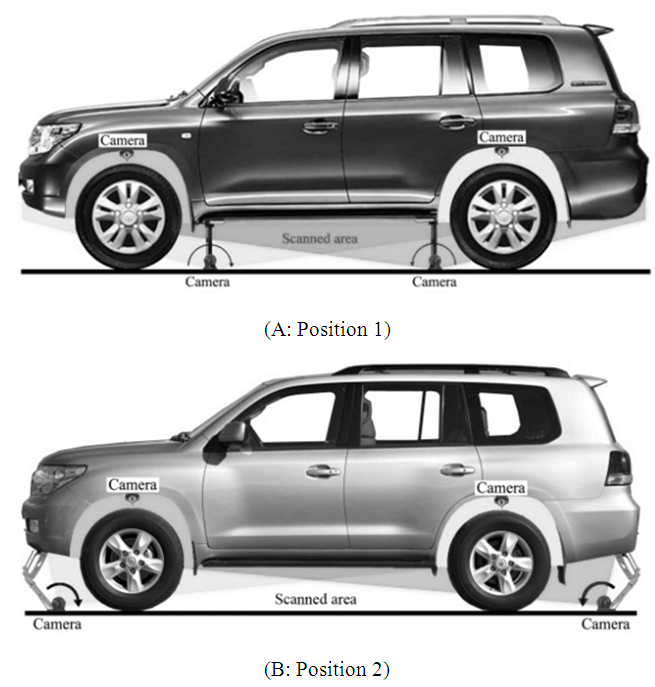 | Figure 6. Camera positions for the proposed system. (A: system attached to front and rear bumper, B: system attached to begin and end of the rocker panel) |
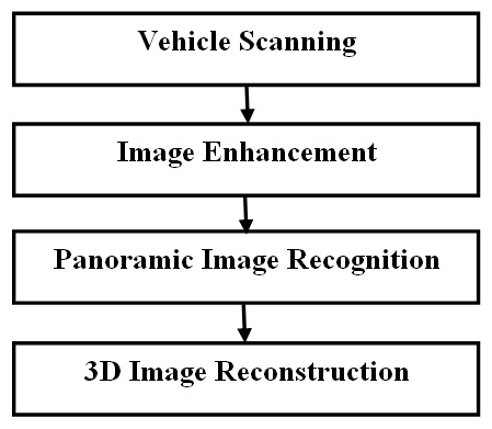
5. Panoramic Images Stitching Using Invariant Features
- This paper implements a modern model for fully automatic panorama stitching. The employ of unchanged local features and a probability model to verify image matches allows us to stitch them fully automatically without user input and recognize different panoramas in unordered image sets. A multi-band combination scheme ensures smooth transitions among images regardless of illumination differences, whilst preserving high frequency details [15]. Potential future ways would be to attempt to distinguish between three-dimensional imagery panoramas (camera fixed), and (camera translation) and to use more frequency bands in the blending scheme.Algorithm 1: Panoramic Image RecognitionInput: n unordered imagesI. Find SIFT features from the n imagesII. Extract k nearest-neighbors for each feature using a k-d treeIII. For every image:(i) Extract m candidate matching images (with the maximum number of feature matches in this image).(ii) Select geometrically appropriate feature matches using RANSAC to solve for the homograph between pairs of images.(iii) Verify image matches using a probability model.IV. Extract the connected combination of image matches.V. To everyone connected component:(i) Perform bundle adjustment to solve for the rotation
 and focal length f of all cameras.(ii) Render panorama using multi-band blending.Output: Panoramic image(s)The system able to automatically match the resent under-vehicle scanning, image with the previous saved images in database to detect any new attached objects to the vehicle, the system alarm to the vehicle owner throw the application software when the scanning detects a threat. The other activity can be performed be the system is night view using the LED built-in with a camera. One of the most important advantage points that make our proposed system better than others UVISs are; the possibility to scan the area located between (front fenders, rear fenders) and tires. For all fenders there is a camera installed in the centered upper part of it. During our Literature reviewing of the UVISs we find that such area has not been addressed. The camera arm should be retractable which means that it can be folded inside an armored compartment to protect it from environmental conditions, Off-road driving, intruder, etc.
 6. 3D Image Reconstruction
- According to owner desire, the proposed UVIS system offers a secondary security service (3D Image construction), If the system detects an object a 3D scanning procedures can be performed, where, the 3D scanning system composed by 6 modules [16]: (a) image acquisition module; (b) scanning module: (c) control software: (d) distance estimation module; (e) 3D image reconstruction; and (f) resulted image output graphic interface. A variety of devices and techniques venture been involve on the previously for 3D Image data acquisition attainment, besides the use of single image reconstruction, structured light technologies [17]. The 3D image scanning is based on laser triangulation and FOV techniques. It enables a perfect 3D image reconstruction with high resolution from different angles, colors and depth variation. (See Figure 7).
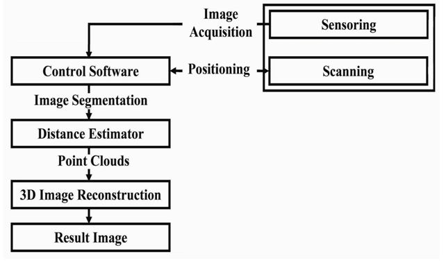 | Figure 7. 3D scanning system [16]: sensoring and scanning modules are implemented in hardware (image acquisition system) and the other modules in software |
6.1. The Principle of Triangulation
- The standard of triangulation keeping on the dropping of a light pattern, i.e., a captured by the digital camera and the line is projected by the laser over an object. The distance from object to system can be calculated by trigonometry, as long as you know a priori distance between the scanning system and the camera [18]. The triangulation system configuration is shown in Figure 8.
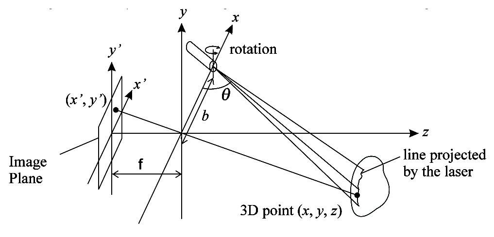 | Figure 8. Geometry of triangulation technique |
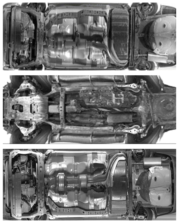 | Figure 9. The proposed UVIS samples Images after enhancement |
7. Conclusions
- The safety of the system owner is the main reason for presenting the proposed UVIS, where we present two types of system hardware installation, both positions serve well, in experiment demonstrate that location 1 present much better images result relating to moving and rotation angles of the camera. The system is reasonably cheap and affordable by an average person, furthermore, it is a mobile system that is attached to the vehicle and can be used anywhere and at any time (night viewing). The system can be applied for vehicle maintenance. Future works are concerned with the improvement of the sensoring module, motion controller module, control software and creating an application program to be instilled on smart phone. Where, the vehicle owner can perform the total security scanning wirelessly from his smart phone by easy and friendly use GUI application. It is expected that the future years will witness a variety of vehicle manufacturing, that offer to customers an option to provide him with UVIS, on the other hands, the 3D resulted image can be enhanced to ensure more accuracy for the system owner, that may involve several image processing technologies.