Tomio Kurokawa
Department of Information Science, Aichi Institute of Technology, Toyota, 470-0392, Japan
Correspondence to: Tomio Kurokawa, Department of Information Science, Aichi Institute of Technology, Toyota, 470-0392, Japan.
| Email: |  |
Copyright © 2012 Scientific & Academic Publishing. All Rights Reserved.
Abstract
A picture maze is a maze on which some picture appears when a player successfully solves it. This paper proposes an automatic generation method of such a maze. Given a binary picture, the method extracts the contours and adjusts the structure of the contours to that of a maze path. Then it connects all the contours to make one single cycle. This cycle is actually the maze solution path which traverses all the contours of the original binary picture. Accordingly, the picture will clearly appear on the maze when it is solved. There are a number of aims in this paper. First is to provide a clear explanation of the structure of an ordinary square grid maze; second is to illustrate how contours of a binary picture are organized as a graph; third is to provide the intuitive and straightforward method to construct a picture maze by converting the contours into one single contour; fourth is to demonstrate that the maze can be complex to bury various binary pictures or shapes such as letters, words, logos, pictograms and sentences, therefore be capable to transmit messages.
Keywords:
Maze, Picture Maze, Picture Maze Generation, Contour, Contour Connection, Structure of Maze, Graph
Cite this paper: Tomio Kurokawa, Picture Maze Generation by Repeated Contour Connection and Graph Structure of Maze, Computer Science and Engineering, Vol. 3 No. 3, 2013, pp. 76-83. doi: 10.5923/j.computer.20130303.04.
1. Introduction
It has been known that contours of a picture play an important role to give the shape understanding of the picture. This research is to illustrate an automatic method to generate a picture maze taking the advantage of the human way of the picture shape understanding. If the maze solution path goes through all the contours of a picture, then it should be expected that the solution of the maze clearly depicts the picture shape. But how to connect the contours of a picture is the problem. This paper shows how to construct a picture maze from a binary picture. It first shows how a maze, a picture maze and contours of a binary picture are organized; and then illustrates a way of systematic successive contour connection to produce a single path. This path goes through all the contours; hence it constructs the maze solution path and then the picture maze. These are explained in the following sections with the experimental data.
2. Related Work
Computerized maze generation with square grids has been around for some years. The article[1] showed various algorithms to generate a square grid based maze, usually used, relating with graph theory. The article[2] presented a number of maze generation algorithms with the relation between path, wall, and coordinates. The article[3] by J. Xu and C.S. Kaplan illustrated complex mazes emphasizing aesthetics for the maze. It also introduced a picture maze[4] called ‘Maze-a-pix’ by illustrating a sample picture maze, which is provided by Conceptis, Ltd.[5]. However, the method of the picture maze generation is not given. The internet site of the company shows various picture mazes and states a history of computer generated picture maze. Y. Okamoto and R. Uehara[6] demonstrated an automatic generation algorithm for a picture maze with the relation to Hamiltonian path. In the research, the maze is so constructed that the player obtains the solution path by painting the picture region with line drawing on the maze. Hamada[7] improved the method[6] by enabling to place the start and goal at different positions.[8] and[9] the earlier studies about this research, explained the picture maze generation with contour connection; however, the development was not sufficient. F.J. Wong and S. Takahashi[10] constructed a hybrid picture maze from two photograph images. This maze is not based on square grids like the mazes[3] but on the special grids computed from the image. Two photo pictures are overlapped in the maze. The maze player depicts an outline of one picture on the other picture background.
3. Maze Structure and Its Graph Representation
There are a number of different representation structures of square grid maze. This paper uses one of them and it is explained in this section. A computer constructed maze is usually represented by a two-dimensional array. Such a maze consists of path and wall. A path cell is either a node or an edge (of a graph). Figure 1 is a sample maze array of size 7x7---where ‘◎’ is a node; ‘e’ is an edge and ‘W’ & ‘w’ are a wall. An edge represents the connection between the two nodes. Diagonally adjacent cells to a node are wall cells; there are four such cells around a node; the vertically or horizontally adjacent cells to a node are edge or wall cells. If the cell represents the connection between the two nodes, then it is an edge cell; otherwise it is a wall cell.The connection between the two nodes is 4-way, vertical or horizontal; and no diagonal connection is allowed. The entire path routes organize a spanning tree. A node and an edge alternately appear along a path. The maze solution of Figure 1 is the path from the start (S) to the goal (G), which is one of the paths from the tree root to a leaf. The maze structure is kept maintained even if the maze is shifted in any direction one or more positions on the array. However, in Figure 1, nodes are placed on (odd, odd) coordinates. If the walls are thinned[11], the maze becomes as presented in Figure 2. This maze, which is to be presented to a player, virtually consists of two kinds of cells, path and wall. However, it represents the corresponding graph with nodes and edges, which cannot be otherwise represented as simply as this structure. So the maze of this structure is said to be an elaborately organized graph. This elaboration is brought about by the edge cells. Without the edge cells, additional information is required to show how nodes are connected[12]. In short, a maze is said to be a collection of nodes and edges like a graph. However, more restrictions are imposed on a maze, physical positions of nodes and edges, the number of edges to be connected to a node and the like.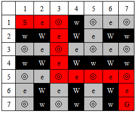 | Figure 1. Maze structure |
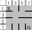 | Figure 2. Maze to be presented to a player |
4. Connection Scheme of Contour Cycles
In general, contours of a binary picture are considered to be a collection of cycles (of a graph). Figure 3 shows two separate cycles can be converted into one single cycle if two lines are properly added. Figure 4 illustrates that the conversion is also possible for the case one cycle is inside the other. If the above conversion process is repeatedly applied, all the contour cycles extracted from a binary picture can be incorporated into one single cycle. Deeply nested contours can be also converted to a single contour. The start and goal points are on some positions of the path. This is the scheme to convert multiple contour cycles into one single cycle, which actually becomes the solution path of the picture maze. 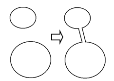 | Figure 3. Two cycles are converted into one single cycle |
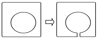 | Figure 4. Two cycles (one in the other) are converted into one cycle |
Figure 5 shows a general situation of the conversion of multiple cycles into a single cycle. It explains the more original shape is maintained if the longer contour lines are incorporated.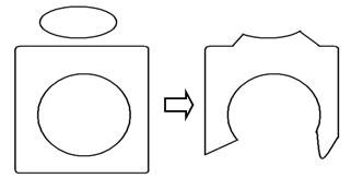 | Figure 5. Three cycles are converted into one single cycle. To maintain the more original shapes, the longer contours should be incorporated |
The conversion is a sort of merging cycles in a graph. An algorithm of merge of cycles is introduced as “merging cyclic paths” in[10] but in a different situation. The merge of cycles is similar to the connection of contour cycles. The mathematical definition is given in[13].
5. Proposed Method
5.1. What the Proposed Method Does
Given a binary picture such as stated in the abstract, the proposed method generates a maze which enables the hidden picture to appear when a player successfully solves the maze. The solution of the picture maze will be the path which traverses all the contours of the buried picture. Figure 6 shows a sample input binary picture of ‘AB.’ Figure 7 is the resultant picture maze generated by using the proposed method. The start and goal points are at the top left corner. Figure 8 demonstrates the solution path with which the buried picture is enabled to appear. As illustrated in Figure 8, all contours of the picture are passed through by the solution path starting from the top left corner and coming back to the goal near the start.  | Figure 6. Input binary picture |
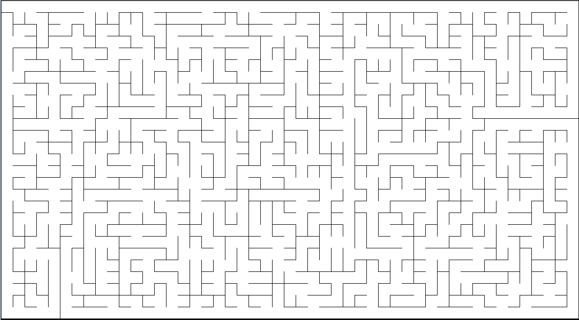 | Figure 7. Picture maze constructed for Figure 6 |
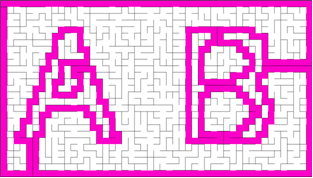 | Figure 8. Solution path for Figure 7 |
5.2. Procedure
This method is programmed with OpenCV library[14] and MS Visual C++ 2010 Express[15]:1. Prepare a binary picture such as Figure 6 and reduce the size if needed. In this sample case, the width and height are divided by 10. 2. Extract the contours of the picture. The resultant output is like Figure 9, which is actually drawn using the output of OpenCV[14].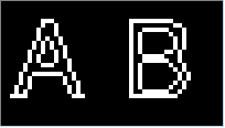 | Figure 9. 8-way connected Contours drawn as they are given by OpenCV |
3. Convert 8-way connection into 4-way if the contour connection is 8-way. The result could be like Figure 10. This is to adjust the contour structure to the maze path.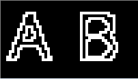 | Figure 10. 4-way connected contours |
4. Expand the picture by two. The resultant output becomes like Figure 11, in which the contours are represented by dotted lines. The dots will be the nodes of the picture maze to be generated.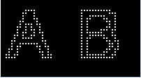 | Figure 11. Contours expanded by two so that these dots are placed as the nodes of the maze |
5. Fill the gaps produced by the expansion. This corresponds to drawing the edges of a graph. The resultant image consists of contour cycles with 4-way connection like Figure 12.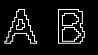 | Figure 12. The gaps produced are filled so that each contour can be a part of a maze path. This gap filling corresponds to drawing edges of a graph |
6. Add the outer frame path to surround the contours and set the start and the goal somewhere on the frame path. The result is depicted in Figure 13. In this sample, the start (S) and the goal (G) are set at the top left corner.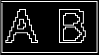 | Figure 13. The outer frame path is added |
7. Apply the conversion scheme, which is explained in Section 3, to the contours. The result is a single cycle, which is actually the solution path, starting from the top left corner, going through all the contours of the picture and getting back to the top left corner (Figure 14).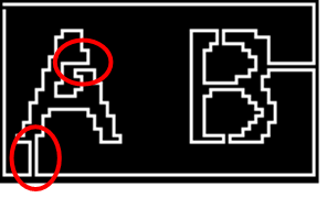 | Figure 14. The solution path is completed. Circled parts are to show different connection patterns |
8. Add random dead-end path branches. This is to hide the solution path. The result may become like Figure 15. It was not intended to best hide the solution. In this figure, some image parts may be dimly seen. This is a drawback of the proposed method. 9. Thin the walls to produce the final maze. This is to make the maze for the player to play easier as well as to hide the solution better. This completes the maze as in Figure 7. 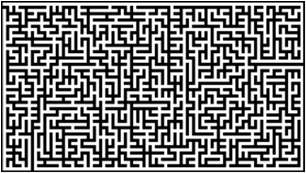 | Figure 15. Random dead-end branch paths are added |
6. Details and Discussions on Solution Path Generating Procedure
6.1. Extraction of Contours
Using OpenCV[14], contours of a binary picture can be obtained. The contours are organized in a binary tree like Figure 16. Each contour (a node of the tree) is represented by a sequence of coordinates. The connection direction is of 8-way. To adjust the structure of the contours to that of a maze path, the conversion from 8-way connection to 4-way has to be made.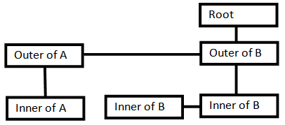 | Figure 16. Contours are organized with a tree structure |
6.2. Foreground Picture and Background Picture
There are two kinds of binary pictures. One is white foreground (Figure 6) and the other is black foreground (Figure 17). Either can be used for the maze generation. However, the outputs by OpenCV are not the same for the two because the contour dots extracted by OpenCV are on the white picture region. The sample picture of ‘AB’ used is the white foreground binary picture as Figure 6.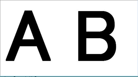 | Figure 17. Black foreground binary picture |
6.3. Generation of Solution Path by Repeated Connection of Contours
The way to connect the contours is explained in this sub-section. Let the outer frame path given on the 6th step of the procedure be the beginning base path to which the contours are to be connected. This path has the start and the goal. The remaining work is to connect each contour in the tree like Figure 16. Traversing the tree by the depth-first order, picking up a contour from the tree and starting from each point on the contour, the procedure seeks a possible connection to the outer already connected path (see Figure 18). The width-first order traversing is also possible. The seeking directions are to the left, to the top, to the left and to the bottom shown by the arrows in Figure 18. This seeking is continued until one feasible connection is found. When it is found, the connection lines are drawn. If not found, next point on the contour is tried. This connecting process is continued until all the contours in the tree are connected. The start position on a contour in seeking a possible connection is randomized. Therefore, the connection line position can be changed by setting different random number seed in the program. The connection lines drawn in the experiment are straight. However, natural curves are probably preferred because straight lines are often seen as a part of the supposedly hidden picture.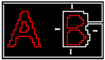 | Figure 18. The outer contour of ‘B’ is just connected to the maze path. The red contours are not yet processed |
6.4. Different Connection Patterns
The patterns of the connecting lines are not all same besides the different directions. As shown by the red-circles in Figure 14, the patterns of the two red-circled parts are different. The upper red-circled part is a little more complex. Before making the connection from a position on a contour to a position on the already constructed path, it is examined if it is possible to connect the two positions in seeking the connection (explained in section 5.3). There are several different connection patterns at both of the start and destination positions. The simplest case is between two flat lines. That is, the start position on the start contour and the destination position on the already connected path have no curve or no zigzag. The explanation about this simplest case is given by using Figure 19 and Figure 20. Figure 19 (a) shows the contours of ‘AB’ which are not yet connected to the frame path, which is the base solution path. Figure 19 (b) presents the completed solution path. Attention should be paid to the connection lines between ‘A’ and ‘B’. When the outer contour of ‘A’ is connected to the outer contour of ‘B’, the outer contour of ‘B’ is already a part of the solution path. Figure 20 illustrates the details of the start and destination positions after the connection is made. There are two connecting end points at each of the start and the destination. Let the two points at the start be (x0, y0) and (x0, y2) and the two points at the destination be (x, y0), (x, y2). These four points are node cells. Starting from x=x0, x is incremented by two until it reaches the already connected path position without encountering any obstacle (like contours which are no yet connected).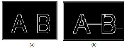 | Figure 19. Contour situations just before (a) and after (b) the connection |
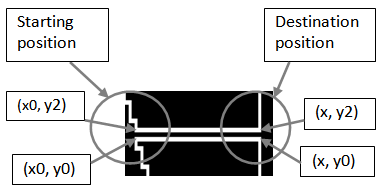 | Figure 20. Situation around connection positions |
As for the start position, depending on the positions of the two points, there are several connecting start patterns; and depending on the positions of the two points at the destination, there are also several patterns. Since the flat pattern is most frequent and easiest to connect, the start position is chosen to be only on the straight line part. Then examining all the patterns at the destination is sufficient enough to find a connection successfully. This is because the flat pattern appears on any contour.There are only five different patters at the destination as shown in Figure 21, where ‘0’ is the path cell. The small arrays with three rows on the left side of Figure 21 represent the situation before connection and those on the right side illustrates that after connection. The case 1 at the top of the figure is the most frequently appearing patterns. Two lines are extended from the start to the destination, left to right. When some already existing (connected) path cells are encountered in seeking the connection, then the connection is made and the edge cells which become unnecessary are removed. The patterns of the cases 2 and 4 as well as the patterns of cases 3 and 5 are symmetrical, respectively. As for 2 and 4, two edge cells and one node cell are removed at the destination. As for 3 and 5, the connecting lines are not straight; they turn 90 degree at the destination point. Figure 21 shows only the cases when the possible connections are sought in the direction to the right. The connections are to be sought in other three directions in the experiments.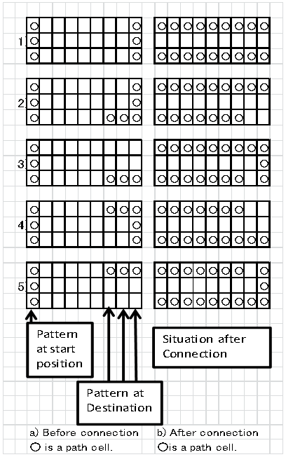 | Figure 21. Connection cell patterns of the start and the destination before and after the connection: The cell with ‘0‘is a path cell; the cell with white space is a wall cell |
6.5. Expansion of Picture and Wall Thinning
The thinning process at the step 9 in the procedure actually cancels the picture expansion by two made at the step 4. Therefore, it is understood that the edge just works as the connection between the nodes virtually not occupying spaces on the maze.
6.6. Random Dead-End Branches and Wall Thinning
The purpose of the addition of random dead-end branches and the wall thinning at the steps of 8 and 9, respectively, in the procedure are mainly to hide the solution path. However, there are cases where some parts of the picture are dimly seen before the maze is solved. This is the drawback of this method. The wider space of display or paper may be necessary to hide it better. By the way, the best way to hide the solution path was not intended.
7. More Complex Pictures Incorporated
Some more complex pictures were tried to be incorporated into the maze. Figure 22 is the maze with Chinese characters meaning “maze.” The zigzag is attached to the frame path in order not to be seen easily. Figure 23 is to show that a short English sentence can be embedded.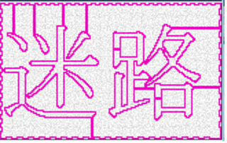 | Figure 22. A more complex picture can be incorporated into the maze |
 | Figure 23. A short English sentence can be buried in the maze |
8. Case of Failure in Maze Generation
According to the experiments so far, the maze generation seems to be successful if the contours generated from the binary picture are ‘regular’. Here, ‘regular’ means the contours are completely closed like a cycle of a graph and have no points shared by two or more contour cycles.Some experiments were done to see what would happen if the generated contours are not ‘regular’. Expecting some irregular situations, the size of the binary picture was reduced to some extent and OpenCV was applied to obtain the contours. Figure 24 shows the effect when a picture size was reduced to 1/20 and 1/18. The original picture is given in (a); (b) is the 8-way connected contours for the 1/20 reduced picture from (a). The two 4-way contours in (c) obtained from (b) overlapped at the top part of ‘B’. And it failed to make the solution path as illustrated in (d). The top part of ‘B’ seems too narrow to have two separate contour lines due to the reduction. For the reduction by 1/18, all the 4-way contours of (e) have no part in common. And it successfully constructed the solution path (f). So it can be said that the construction of a picture maze is possible if the picture is good enough to generate ‘regular’ contours. 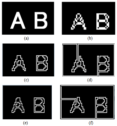 | Figure 24. Success and failure in solution path construction: (a) Original binary picture; (b) 8-way connected contours for the size reduction of 1/20; (c) 4-way connected contours for the size reduction of 1/20; (d) failed solution path for the size reduction of 1/20; (e) 4-way connected contours for the size reduction of 1/18; (f) successful maze path for the size reduction of 1/18 |
9. Comparison with Other Researches
The paper[6] sought a Hamiltonian path within the picture region by ensuring the existence of the Hamiltonian path with the 2*2 extension of the square grid picture. This method requires that the input binary picture is connected. The resulting solution path represents the exact original picture; the procedure is simple and fast. However, the start and the goal must be placed side by side, which is later improved by[7].The method of[10] constructs a picture maze using two photo pictures---primary and secondary. It organizes a special grid based on the primary. The secondary is used to make the shape which is the one appearing on the primary when the maze is solved. A sketch like picture appears when the maze is solved. The maze is artistic and of high quality. The drawback may be that a large amount data processing is necessary for the maze construction.As for the proposed method of this research, it is simple, intuitive to construct and capable of handling complex and precise binary pictures such as symbols, letters, words, sentences and the like. The solution enables a precise picture to appear. The drawback is that the parts of solution path are sometimes dimly seen. The avoidance is left for the future work.
10. Conclusions
This paper describes the method which can construct the picture maze from a wide range of binary pictures. The maze player will draw the solution path just like ‘picture cutting.’ There are several significant features for the proposed method:1. The maze solution path clearly depicts the picture which is originally given. 2. It does not require the connectivity of the picture. Therefore, it can bury a wide range of binary image such as letters, symbols, words, logos, and short sentences. So the maze can be used in various situations such as message finding.3. The method is based on a graph theoretical scheme: Multiple contour cycles can be converted into one single one.4. This paper clearly explains the picture maze structure in relation to a graph.5. The proposed method is very simple in procedure and in concepts; the concept is especially straightforward and intuitive. 6. There are cases where parts of the picture are sometimes seen dimly. This is a drawback.
References
| [1] | “Maze generation algorithm,”http://en.wikipedia.org/wiki/Maze_generation_algorithm, Accessed 2013/01/09 |
| [2] | T. Hosokawa, “Maze,” http://aanda.system.to/ Accessed 2013/01/25 |
| [3] | J. Xu and C. S. Kaplan, “Image-Guided Maze Construction,” ACM Transactions on Graphics, 26, 3, Article 29, pp.1-9, 2007 |
| [4] | J. Xu and C. S. Kaplan, “Vortex maze construction,” Journal of Mathematics and the Arts, 1, (1), pp.7-20, 2007 |
| [5] | Conceptis puzzles,“Maze-a-PiX,” http://www.conceptispuzzles.com/, accessed 2013/01/09 |
| [6] | Y. Okamoto and R. Uehara, “How to make a picturesque maze,” Proc. Canadian Conf. on Computational Geometry, pp.137-140 , 2009 |
| [7] | H. Hamada,http://www.lab2.kuis.kyoto-u.ac.jp/~itohiro/Games/100301/100301-11.pdf , accessed 20013/01/12 |
| [8] | T. Kurokawa, K. Mori, and T. Mizuno, ”Automatic construction of picture maze by repeated contour connection,” Thailand-Japan Joint Conference on Computational Geometry and Graphs, pp.5-6, 2012 |
| [9] | T. Kurokawa, “Picture maze generation and its relation to graphs,” 2013 SHIKOKU-SECTION JOINTCONVENTION RECORD OF THE INSTITUTE OF ELECTRICAL AND RELATED ENGINEERS, p.231, 2013 |
| [10] | F. J. Wong and S. Takahashi, “Flow-based Automatic Generation of Hybrid Picture Mazes,” Computer Graphics Forum, 28, (7), pp.1975-1984, Wiley-Blackwell, 2009 |
| [11] | S. Ishida, "Algorithm of automatic maze generation," http://www5d.biglobe.ne.jp/%257estssk/maze/make.html, (Japanese), Accessed 2013/10/8 |
| [12] | “How to Build a Maze,”http://www.mazeworks.com/mazegen/mazetut/index.htm, Accessed 2013/1/26 |
| [13] | G. Gutin, and R. Holloway, “Traveling Salesman Problems,” in J. L. Gross and J. Yellen, (Eds.), Handbook of Graph Theory, pp.279-299, CRC Press, 2004. |
| [14] | http://jaist.dl.sourceforge.net/project/opencvlibrary/opencv-win/2.1/ Accessed Oct., 2011 |
| [15] | http://www.microsoft.com/ja-jp/dev/express/default.aspx, Accessed 2012/10/15 |


 Abstract
 Reference
 Full-Text PDF
 Full-text HTML