Yuri Baida1, 2, Anton Lechenko1, 2, Andrey Efimov2, Alexander Butuzov2
1Moscow Institute of Physics and Technology (State University), Moscow, Russian Federation
2ZAO “Intel A/O”, Moscow, Russian Federation
Correspondence to: Yuri Baida, Moscow Institute of Physics and Technology (State University), Moscow, Russian Federation.
| Email: |  |
Copyright © 2012 Scientific & Academic Publishing. All Rights Reserved.
Abstract
For new hardware/software co-designed CPU architectures there is a need for fast and flexible performance simulation to perform extensive design space exploration in both software and hardware domains. To confirm reliability of design decisions, the simulator should also be accurate, which is usually achieved at the cost of reduced simulation speed. Although FPGA-accelerated simulators have dramatically higher speed than software simulators, such models require much higher development effort. An FPGA-based model generally assumes a top-down design flow, where the system can be tested only after all units have been developed. The paper describes a method and system for bottom-up development and automated unit-level testing of FPGA-based cycle-accurate simulator leveraging functionality of existing software simulator.
Keywords:
Microprocessor, CPU, Cycle-accurate, Simulator, Simulation, Model, Unit-level, Testing, FPGA
Cite this paper: Yuri Baida, Anton Lechenko, Andrey Efimov, Alexander Butuzov, Method and System for Automated Unit-Level Testing of FPGA-based Cycle-Accurate Microprocessor Simulator Using Software Simulator as a Golden Model, Computer Science and Engineering, Vol. 3 No. 3, 2013, pp. 51-55. doi: 10.5923/j.computer.20130303.01.
1. Introduction
An important part of most CPU microarchitecture development projects is a performance model – a very detailed cycle-accurate model which helps conduct detailed performance characterization studies.The conventional approach is to develop performance models in software using high-level programming languages like C++. This approach leverages power and flexibility of the high-level language, availability of tools, dedicated libraries and frameworks, and, of course, skilled programmers.Unfortunately, conventional software simulators provide accuracy at the expense of simulation speed of no more than a few thousand model cycles per second. Thus, running long workloads with accurate performance tracking is practically impossible due to unacceptably long execution times.In the realm of RTL (register-transfer level) simulation, tremendous speedup can be achieved using FPGA-based prototypes[1]. E.g., Intel Atom[2] and Intel Nehalem[3] CPU core models were successfully implemented on FPGAs with emulation frequency of 50 MHz and 520 KHz respectively. However, development of FPGA-based prototypes is very difficult, expensive, time-consuming and possible only during the late stages of design flow after completion of RTL development.Recent investigations[4] explored FPGA-accelerated processor simulation which is possible without final RTL and thus can be done at early stages of CPU design flow. This means that the hardware description used to configure the FPGA is not an exact description of the target circuit. Instead, it is a behavioural description of the target circuit external timing, e.g. the simulator may take any number of FPGA clock cycles to simulate one model clock cycle.Development of FPGA-based models generally assumes top-down design flow, where all units must have been created before the full system can be tested. The challenge pursued by this paper is to provide instrumentation for independent bottom-up development and automated unit-level testing, leveraging functionality of an existing software simulator.
2. Underlying Technology
2.1. Latency-delay Port Specification
The microprocessor performance model in this paper is specified using a latency-delay port (LDP) specification, an existing technique for describing a cycle-by-cycle model of a target hardware system[5].The set of states of the target microprocessor is decomposed into sets of states of individual modules (branch predictors, caches, etc.) which can be written using set theory notion as a Cartesian product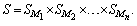 | (1) |
Modules are arranged in a directed multigraph connected by ports (see Figure 1). A port is simply a communication primitive annotated with a static latency, representing the number of model cycles that messages takes to pass through the port.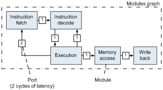 | Figure 1. LDP-specification of a simple five-stage CPU pipeline |
An important basic concept of LDP-specification we leverage in this paper is that modules can communicate only by sending messages through ports.
2.2. Bluespec SystemVerilog
In this study, we use Bluespec SystemVerilog hardware description language (HDL), a high-level object-oriented language[6] based on a computational model, where all hardware behaviour is described as a set of rules (aka guarded atomic actions).The main benefits of Bluespec HDL are: − strong type checking,− polymorphism (like in C++ templates),− built-in high-level modules (e.g. FIFO),− integration with Verilog and VHDL RTL.The Bluespec compiler transforms source code into high-quality Verilog RTL, which can be further synthesized into net lists using well-known industrial CAD tools such as Synopsys Synplify Pro or Xilinx ISE.
2.3. The HAsim Framework
HAsim is a framework for FPGA-based cycle-accurate microprocessor simulators jointly developed by Intel and Massachusetts Institute of Technology[7].HAsim offers a method for writing timing models that run on FPGAs, using programming techniques similar to software-based timing models. It decreases development effort providing a LEAP virtual platform, a set of interfaces for FPGA application with a consistent set of useful services and device abstractions, a memory hierarchy and a flexible RRR (Remote Request-Response) asynchronous communication protocol across a range of physical FPGA platforms.However, the original HAsim methodology uses top-down design flow and doesn’t provide methods and tools for independent unit-level development. Although we use the HAsim framework for FPGA-based hardware models, the proposed method can be used with any simulation framework which employs the LDP-specification described earlier.
3. Methodology
3.1. General Idea
As opposed to the conventional methods, this paper proposes a method for bottom-up independent development of units and system for automated unit-level testing, which leverage the functionality of the existing software simulator.From the formal point of view, taking into account equation (1), bottom-up design and unit-level testing means that we should implement and check only the | (2) |
number of states for each individual module and | (3) |
states to test all units instead of 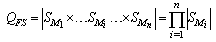 | (4) |
states in case of full-system testing.Suppose the microprocessor consists of N elementary gates with k states (e.g.,  for a NAND gate) equally distributed across n modules, we have the ratio
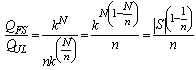 | (5) |
that shows the benefit of the unit-level testing process.
3.2. Design Flow
Integrated design flow we propose consists of 3 stages (see Figure 2), and at each stage the design is verified using the reference software model. The verification process at each stage is automated.The development process starts from exploring the software model (golden model) and implementation of port-equivalent modules in Bluespec HDL. This stage is the most time-consuming since a developer should not only study the software implementation of the module but also implement it in Bluespec HDL.Since modules communicate only through ports, the module’s logic consists of 3 main parts:− read messages from the input ports;− process input data according the given algorithm;− write messages (if any) in the output ports.The handler of each port is usually implemented by a separate Bluespec HDL rule. This well corresponds to the independent nature of ports and allows adding new ports to the design without modification of the existing code.In the next stage of the flow, ports of the software model are replaced with special extended ports capable of saving the trace of messages passed through them. Traces of messages passed through input ports of the module, are used further as testing stimuli, while the ones from output ports are used as a reference. Once generated by the golden model, traces are stored in a special database. Once the unit has been implemented in Bluespec HDL, it is wrapped into a unit-level model described in the next section and is ready to be simulated at each subsequent stage without modifications.After successful compilation to Verilog RTL description by the Bluespec compiler, the unit model can be run by the native Bluespec simulator (Bluesim) or by a well-known industrial RTL simulator (e.g., Synopsys VCS). From our experience, Bluesim is roughly twice as fast as VCS.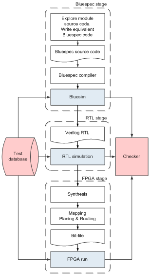 | Figure 2. Integrated methodology design flow |
Finally, the verified RTL code is synthesized, mapped, placed and routed by FPGA vendor implementation tools. The generated bit-file is loaded into FPGA and the model is executed using the same test vectors as those used by the all stages of model development.
3.3. Unit-level Model
Using the proposed method, each module of the model can be developed and tested independently, thus the total development time is dramatically decreased. On the other hand, this requires a unit-level testing environment, which is used before the full model is completed. Each unit-level model reads data from the test database to emulate absent neighbour modules. The unit-level model is verified by comparing the output trace with the reference trace produced by the corresponding module of the software simulator. The unit-level model structure is presented in Figure 3. The unit stub reads test vectors from the software model received via RRR channels through loggers’ hub and writes the data to the corresponding ports. The particular test traces from the database can be stored in FPGA as well as loaded on-the-fly from the machine hosting the FPGA.The unit stub gathers output data and sends it back to the test environment. The loggers’ hub concentrates streams from all loggers and controls model communications via the dedicated RRR channel. The unit stub and loggers are connected with loggers’ hub by soft connections[8] – communication primitives that free the designer from coding the stub-to-hub interfaces manually. 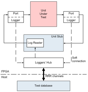 | Figure 3. Unit-level model structure |
As one can see, the entire infrastructure for automated testing is localized on the level of the HAsim framework libraries, while the module code is unaffected. Thus the used validation methodology is highly scalable and flexible.In spite of the complexity of the testing system, the whole testing environment, including unit stub, loggers, etc. can be generated automatically by a special script using the extended LDP-specification of the model (e.g. stored in an XML format). Therefore, overhead on unit-level testing is minimized.
4. Evaluation
In this section we evaluate the proposed method and system in two ways. First, we determine the design effort savings enabled by the use of the proposed technique. Second, we evaluate the host machine disk space usage.Evaluation is provided with an example of a modern out-of-order superscalar quad-core microprocessor with the following structure shown in Figure 4.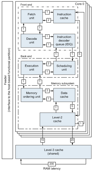 | Figure 4. The microprocessor model structure |
4.1. Design Effort
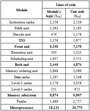
To evaluate effectiveness of the proposed method, we calculate the number of lines of source code (so called LOC metric) and the well-known COCOMO 2.0 (Constructive Cost Model)[9] cost estimation regression model developed by B.W. Boehm.For LOC calculation, we take into account only lines written manually; blank and comment lines are ignored.The source code size for all modules of the developed microprocessor simulator (as well as the size of generated source code of service unit stub modules) is shown in Table 1. Table 1. Lines of code for all simulator modules (written manually) and corresponding unit stubs (generated automatically)
 |
| |
|
Considering cycle-accurate hardware simulator modules’ logic implementation as an “embedded project” using the COCOMO terminology, we have estimated design effort as: | (6) |
The code of unit stubs is much simpler than simulation logic, so we use “organic project” coefficients: | (7) |
From the other hand, the real model development took 11 months of 4 people, which gives us 44 man-months effort value. COCOMO-based effort estimation is roughly 3 times higher, which is explained by the fact that the COCOMO assumes top-down development process without automated testing system we have.Automatic tools for unit stubs’ code generation saved us about 60 man-months of design effort while developing the tools took only about 3 man-months. Finally, all these factors show very high effectiveness of the proposed methodology.
4.2. Disk Space Usage
Disk space of the host machine is highly utilized by test vectors once generated using reference software simulator. In our case test vectors for the database of 670 tests consume about 71 GB.Although test database requires considerable amount of disk space, on-the-fly generation is unacceptable since the unit-level model speed will be bounded by the speed of the software model.While running a regression test, about 15 GB is consumed by the testing system, and the model itself with all libraries occupies about 150 MB. This means that about 100 GB of hard disk space will be enough for test database storage and regression testing.The full-system testing requires up to 100x less disk space for the database since the full model has a very limited number of input/output ports. However, disk space is much cheaper today than developers’ time, thus larger disk space consumption should be considered as a very small and acceptable disadvantage of the proposed method. There are also known test traces archiving techniques which could be used in case of much larger test data base[10, 11].
5. Conclusions
In this paper we presented a method of unit-level testing of an FPGA-based cycle-accurate microprocessor simulator using a software simulator as a golden reference.The proposed bottom-up unit-level development and validation flow significantly reduces debug and validation efforts (all model units can be developed and tested independently) as opposed to the conventional top-down design flow, where all units must be developed first, and only the full system can be tested.Test infrastructure for automated validation is localized while the model unit code is unaffected, making proposed validation methodology highly scalable with little effort as opposed to traditional hardware validation techniques where unit code should be modified, which imposes huge overhead in terms of time and effort.
ACKNOWLEDGEMENTS
We want to express our sincere appreciation to each of those who participated in developing the FPGA-based performance model using the proposed method: Roman Fadeev, Mikhail Tsvetkov and Roman Khvatov.We would also like to thank the HAsim team, namely Joel Emer, Michael Adler, Michael Pellauer, Angshuman Parashar, Kermin Fleming and all others who contributed in HAsim development.Many thanks to Sergey Shishlov whose valuable input helped us shape the narrative in this paper.
References
| [1] | Simoneau W., Sendag R. “An FPGA-based multi-core platform for testing and analysis of architectural techniques”. Proc. of IEEE International Symposium on Performance Analysis of Systems and Software. 2012, pp. 68-77. |
| [2] | Wang P. H., Collins J. D., Weaver C. T., et al. “Intel Atom processor core made FPGA-synthesizable”. Proc. of ACM/ SIGDA International Symposium on Field Programmable Gate Arrays, 2009, pp. 209-218. |
| [3] | Schelle G., Collins J., Schuchman E., et al. “Intel Nehalem processor core made FPGA synthesizable”. Proc. of ACM/ SIGDA International Symposium on Field Programmable Gate Arrays, 2010, pp. 3-12. |
| [4] | Pellauer M., Vijayaraghavan M., Adler M., et al. “Quick performance models quickly: closely-coupled partitioned simulation on FPGAs”. Proceedings of IEEE International Symposium on Performance analysis of systems and software, 2008, pp. 1–10. |
| [5] | Pellauer M., Vijayaraghavan M., Adler M., et al. “A-Port networks: preserving the timed behavior of synchronous systems for modeling on FPGAs”. ACM Transactions on reconfigurable technology and systems, 2009, vol. 2, no. 3, pp. 1-26. |
| [6] | Nikhil R. S. “Abstraction in hardware system design”. ACM Queue, 2011, vol. 9, no. 8, pp. 40-54. |
| [7] | Pellauer M., Adler M., Kinsy M., et al. “HAsim: FPGA-based high-detail multicore simulation using time-division multiplexing”. Proc. of IEEE International Symposium on High performance computer architecture, 2011, pp. 406-417. |
| [8] | Pellauer M., Adler M., et al. “Soft connections: addressing the hardware-design modularity problem”. Proceedings of Design automation conference, 2009, pp. 276-281 |
| [9] | Boehm B. W., Abts C., Brown W. et al. “Software cost estimation with Cocomo II”, Prentice Hall, 2000, 544 p. |
| [10] | Johnson E., Ha J., Baqar Z. M. “Lossless trace compression”. IEEE Transactions on Computers, 2001, vol. 50, no. 2, pp. 158–173. |
| [11] | Burtscher M., Ganusov I., Jackson S. J. et al. “The VPC trace-compression algorithms”. IEEE Transactions on Computers. 2005, vol. 54, no. 11, pp. 1329–1344. |
 Abstract
 Reference
 Full-Text PDF
 Full-text HTML