Mohamed Mostafa Abd Allah 1, 2, Gasim Alandjani 1
1Royal Commission, Yanbu Industrial Collage, EIET Department , Yanbu, KSA
2Minia University, Faculty of Engineering, Department of Electrical, Communications and Electronics section, Egypt
Correspondence to: Mohamed Mostafa Abd Allah , Royal Commission, Yanbu Industrial Collage, EIET Department , Yanbu, KSA.
| Email: |  |
Copyright © 2012 Scientific & Academic Publishing. All Rights Reserved.
Abstract
In this paper we will overview the use of data hiding techniques in digital images. In particular we will describe how one can use steganography to hide biometric information in a digital image. This proposed technique proposes a quite simple solution for inserting a secure authentication watermarking in dispersed-dot halftone images. This technique explain how, the hidden biometric data are extracted accurately from the carrier image using a secret key and describe how it can be applied to any kind of binary images including clustered-dot halftones. Furthermore, this technique explains how data are hidden in the host image in an adaptive way to minimize possible degradations to that image. The proposed technique not only provides a better way for embedding large amounts of data into cover images with imperceptions, but also offers an easy way to accomplish secrecy. This method provides better results as compared to LSB replacement method where the distortions are spread all over the image.
Keywords:
Steganography, Bio-Data, Information Embedding, Secret Communication
Cite this paper:
Mohamed Mostafa Abd Allah , Gasim Alandjani , "A Novel Scrambling Algorithm for Bio-Data Hiding Technique", Computer Science and Engineering, Vol. 1 No. 2, 2011, pp. 51-56. doi: 10.5923/j.computer.20110102.09.
1. Introduction
Data hiding represents a class of processes used to embed data, such as copyright information, into various forms of media such as image, audio, or Bio data with a minimum amount of perceivable degradation to the “host” signal[3]. One of the data hiding techniques is image watermarking. The main purposes of image watermarking include copyright protection and authentication. In such applications, it is required that the embedded information be unaltered, or altered only up to an acceptable degree of distortion, no matter how the watermarked image is attacked. Many other new applications of watermarking are also introduced such as broadcast monitoring, proof of ownerships, transactional watermarks, copy control, and covert communication.[4] Steganography is an important sub discipline of information hiding. It is the art of covered or hidden writing. The purpose of steganography is covert communication to hide a message from third party. Ancient examples of steganography include etching messages or images in wooden tablets and covering them with wax and tattooing a message on the shaved scalp of a slave, and then sending the slave to the desired recipient after the slave’s hair has re-grown.[ 9],[17] Computer-based image steganography is one way of data hiding which provides data security in digital images. It is considered as a technique inspired from ancient steganography. The aim isto embed and deliver secret messages in digital images without any suspiciousness. The secret message might be a caption, a plain Bio data, another image, a control signal that can be represented in bit stream form. The secret message may be compressed and encrypted before the embedding steps begin.[8]. The proposed data hiding in image can be done using spatial domain techniques. Spatial domain techniques give better data hiding capacity with less robustness. LSB replacement[9][12], patchwork[3], masking and filtering [11],[12] are some of the examples of spatial domain techniques. All the values in a certain range (i.e., all the values with an identical index) are considered as close enough. That is, if a difference value in a range is replaced by another in the same range, the change presumably cannot be easily noticed by human eyes. Some bits of the secret message are embedded into a two-pixel block by replacing the difference value of the block with one identical index. In other words, the gray values in each two pixel pair are adjusted by two new ones whose difference value causes changes unnoticeable to an observer of the stego-image. In this paper, a cover image is divided into a number of non-overlapping two-pixel blocks. Each block is categorized according to the difference of the gray values of the two pixels in the block. A small difference value indicates that the block is in a smooth area and a large one indicates that it is in an edged area. In other word, assume that the gray values of Pi and Pi+1 are gi and gi+1 respectively, then a difference value d is computed from every non-overlapping block of two consecutive pixels (Pi and Pi+1) as gi+1 ─ gi, which may be in the range from -255 to 255. A block with d close to 0 is considered to be an extremely smooth block, whereas a block with d close to -255 or 255 is considered as a sharply edged block. The pixels in edged areas may tolerate larger changes of pixel values than those in the smooth areas. So, more data can be embedded in edged areas than in the smooth areas. And it is in this way the changes in the resulting stego-image are unnoticeable.This paper is organized as follows: In section 2, proposed steganography conceptual framework and the pixel scrambling algorithm were discussed. The embedded method is explained in detail and compared with different ranges in Section 3. In Section 4, we the Experimental work and outlining further possible security improvements were introduced. In section 5, we briefly evaluated our algorithm and provided a discussion. Finally in section 6, we concluded the paper with some future directions.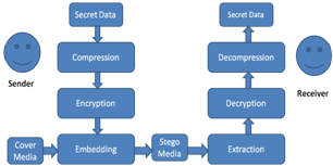 | Figure 1. Generic Steganographic Technique |
2. Bio-Data Steganographic Techniquie
In this paper we observe that Bio-Data contain a lot of redundant data which doesn’t represent any useful information e.g. the white background on which doesn’t offer any useful information. Therefore, even if we do not hide that information it does not make a big difference. Based on this observation we understood that it would be useless to hide this portion in a cover image. We even realized that if we compress the fingerprint image it won’t be as small as an image which only has Bio data without any white background. The point that we want to focus here is the background information is useless and even compressing and hiding it would require a lot of space and doing so wouldn’t offer us any useful gain. We only hide that portion of a Bio-Data which represents information and we omit the rest. For doing so we select an original image (OI) of the same size as the Bio-Data (BD) and modify those pixels in the original image OI, which represent information in the Bio-Data BD. Hence we only hide the portion from the fingerprint image which represents Bio data. Examples of these images used in the paper are shown in Figure 2. A detailed description of our technique is explained in the next section. A generic steganographic technique is described in Fig. 1. The Sender wants to communicate a secret message to a receiver. The message is first compressed and then encrypted.The encrypted message can now be secretly hidden in a cover medium. A stego-key is generated and shared between the sender and the receiver.This stego-key is used to randomly select and replace the redundant bits from the cover media in order to hide the secret message. Redundant bits are defined as those bits in the cover media, which if changed won’t change the cover media to a great extent. After embedding is finished the cover media can be transmitted to the receiver. At the receiving end, the receiver, having the proper stego-key and decryption key, can extract the secret message from cover media. The success of steganography is dependent on the secrecy of the cover media. Once the cover media is public then the success depends on the robustness of the algorithm used.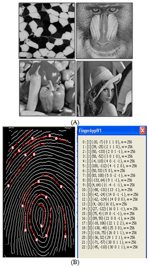 | Figure 2. (A) Cover Image IO (B) Bio-Data BD |
2.1. Embedding Secret Messages
The proposed method for embedding secret messages into a gray-valued cover image uses the fact that, Human visual system is having low sensitivity to small changes in digital data. It modifies pixel values of image for data hiding. Cover image is partitioned into non-overlapping blocks of two consecutive pixels. Difference between the two consecutive pixel values is calculated. These difference values are classified into number of ranges. Range intervals are selected according to the characteristics of human vision’s sensitivity to gray value variations from smoothness to contrast. A small difference value indicates that the block is in a smooth area and a large one indicates that it is in an edged area. The pixels in edged areas can tolerate larger changes of pixel values than those in the smooth areas. So, in the proposed method we can embed more data in edged areas than in the smooth areas. The difference value then is replaced by a new value to embed the value of a sub-stream of the secret message. The number of bits which can be embedded in a pixel pair is decided by the width of the range that the difference value belongs to. The method is designed in such a way that the modification is never out of the range interval. This method not only provides a better way for embedding large amounts of data into cover images with imperceptions, but also offers an easy way to accomplish secrecy. This method provides an easy way to produce a more imperceptible result than those yielded by simple least-significant-bit replacement methods. The embedded secret message can be extracted from the resulting stego-image without referencing the original cover image. Experimental results show the feasibility of the proposed method.
2.2. Hide Bio-Data in a Digital Image
Pixel Scrambling is a technique to hide Bio-Data in a digital image. It’s a one-to-one matching between the pixels from the cover image to the pixel in BDI. The only limitation on message length is that message length in bits should be smaller than or equal to the number of pixels in the image. However, embedding a large message comparable to the image size increases the likelihood of making detectable changes inconsistent with the dithering algorithm. Detailed analysis of delectability of hidden messages as a function of message length will be part of a future research. The cover images are 256 gray-valued ones. A difference value d is computed from every non-overlapping block of two consecutive pixels, say Pi and Pi+1, of a given cover image. The way of partitioning the cover image into two-pixel blocks runs through all the rows of each image in a zigzag manner, as shown in Fig. 3 Assume that the gray values of Pi and Pi+1 are gi and gi+1 respectively, then d is computed as gi+1 ─ gi, which may be in the range from -255 to 255. A block with d close to 0 is considered to be an extremely smooth block, whereas a block with d close to -255 or 255 is considered as a sharply edged block. By symmetry, only absolute values of d (0 through 255) are considered and classified into a number of contiguous ranges, say Ri where i = 1,2,………,n. These ranges are assigned indices 1 through n. The lower and upper bound values of Ri are denoted by li and ui, respectively, where li is 0 and un is 255. The width of Ri is ui - li +1. The width of each range is taken to be a power of 2.This restriction of widths facilitates embedding binary data. The widths of the ranges which represent the difference values of smooth blocks are chosen to be smaller while those which represent the difference values of edged blocks are chosen to be larger. That is, ranges are created with smaller widths when d is close to 0 and with larger widths when d is far away from 0 for the purpose of yielding better imperceptible results. A difference value which falls in a range with index k is said to have index k. All the values in a certain range (i.e., all the values with an identical index) are considered as close enough. That is, if a difference value in a range is replaced by another in the same range, the change presumably cannot be easily noticed by human eyes. Some bits of the secret message are embedded into a two-pixel block by replacing the difference value of the block with one with an identical index, i.e., a difference value in one range is changed into any of the difference values in the same range. In other words, the gray values in each two pixel pair are adjusted by two new ones whose difference value causes changes unnoticeable to an observer of the stego-image.
3. Bio Data Embedding
Consider the secret message as a long bit stream. Every bit in the bit stream is embedded into the non overlapping two-pixel blocks of the cover image. The number of bits which can be embedded in each block varies and is decided by the width of the range to which the difference value of the two pixels in the block belongs. Given a two-pixel block B with index k and gray value difference d, the number of bits, say n, which can be embedded in this block, is calculated by 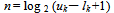 | (1) |
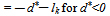
Since the width of each range is selected to be a power of 2, the value of n is an integer. A sub-stream S with n bits is selected next from the secret message for embedding in B. A new difference d ' then is computed by  | (2) |
 | (3) |
 | Figure 3. Construction of non-overlapping two pixel blocks by zigzag scanning of the image rows |
Where b is the value of the sub-stream S. Because the value b is in the range from 0 to uk ─ lk, the value of d* is in the range from lk to uk. According to the previous discussions, if d is replaced with d* the resulting changes are presumably unnoticeable to the observer. Then b is embedded by performing an inverse calculation from d* described next to yield the new gray values (gi', gi+1') for the pixels in the corresponding two-pixel block (Pi', Pi+1') of the stego-image. The embedding process is finished when all the bits of the secret message are embedded. The inverse calculation for computing (gi', gi+1') from the original gray values (gi, gi+1) of the pixel pair is based on a function f ((Oi , Oi+1) ,m ) which is defined to be | (4) |
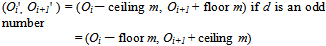 | (5) |
if d an is even numberWhere  | (6) |
The above equation satisfies the requirement that the difference between Oi' and Oi+1' is d*. It is noted that a distortion reduction policy has been employed in designing Equation (4) and (5) for producing Oi' and Oi+1' from Oi and Oi+1 so that the distortion caused by changing Oi and Oi+1 is nearly equally distributed over the two pixels in the block. The effect is that the resulting gray value change in the block is less perceptible.
3.1. Falling Off Checking Process
In the inverse calculation, a smaller value of d* produces a smaller range interval between Oi' and Oi+1' while a larger d* produces a larger interval. So, (Oi , Oi+1) may produce invalid (Oi', Oi+1' ) , i.e., some of the calculations may cause the resulting Oi', or Oi+1' to fall off the boundaries of the range[0, 255 ].Although new values may be re-adjusted to the two new values into the valid range of[0,255] by forcing a falling-off boundary value to be one of the boundary values of 0 and 255, and adjusting the other to a proper value to satisfy the difference d*, yet this might produce abnormal spots in contrast with the surrounding region in some cases. To solve this problem, a checking process is used to detect such falling off-boundary cases, and abandon the pixel blocks which yield such cases for data embedding. The gray values of the abandoned blocks are left intact in the stego-image. This strategy helps to distinguish easily blocks with embedded data from abandoned blocks in the process of recovering data from a stego-image, which will be discussed in the next section. It is noted that such abandoned pixel blocks are very few in real applications according to the proposed method.The proposed falling-off-boundary checking proceeds by producing a pair of (ĝi ,ĝi+1) from the inverse calculation of the value of the function f ((Oi, Oi+1), uk─d). Since uk is the maximum value in the range from lk to uk, the resulting pair of (ĝi, ĝi+1) produced by the use of uk will yield the maximum difference. That is, this maximum range interval ĝi+1 ─ ĝi covers all of the ranges yielded by the other (ĝi , ĝi+1) pairs. So, the falling-off boundary checking for the block can proceed by only examining the values of (ĝi ,ĝi+1) which are produced by the case of using uk. If either of ĝi or ĝi+1 fall off the boundary of 0 or 255, then regard the block to have the possibility of falling-off, and abandon the block for embedding data.
3.2. Extracting the Embedded Message from Stego Image
The process of extracting the embedded message proceeds by using the same traversing order for visiting the two-pixel blocks as in the embedding process. Each time visit a two-pixel block in the stego-image and apply the same falling-off boundary checking as mentioned previously to the block to find out whether the block was used or not in the embedding process. Assume that the block in the stego-image has the gray values (Oi* , Oi*+1),and that the difference d *of the two gray values is with index k. Apply the falling-off-boundary checking process to (Oi* , Oi+1* ) by using f ((Oi* , Oi*+1), uk ─ d *) | (7) |
If either of the gray values of the computed values (ĝi*, ĝi*+1) falls off the boundaries of the range[0,255], then it means that the current block was not used for embedding data, or that the block was abandoned in the embedding process. On the contrary, if both of the values (ĝi*, ĝi*+1) do not fall off the range, it means that some data was embedded in the block. The value b, which was embedded in this two-pixel block, is then extracted out using the equation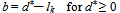 | (8) |
 | (9) |
3.3. Signal to Noise Ratio Calculations
When we hide the data in the cover image means we are adding noise or distortion in that image. It is necessary to calculate Peak signal to noise ratio (PSNR) and root mean square error (RMSE).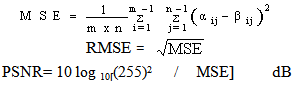
| Table 1. Hiding capacity using pixel value differencingmethod |
| | Cover image | Maximum capacity in bytes | | Embedding using Range 1 | Embedding using Range 2 | Embedding using Range 3 | Embedding using Range 4 | | Lena | 28883 | 40497 | 51692.3 | 66074 | | Peppers | 27496.9 | 38775.9 | 50684.9 | 65614.8 | | Cell | 23159.6 | 36683.8 | 50282.3 | 59705.9 | | Mandrill | 37189.6 | 49982 | 57116 | 67939 |
|
|
Where i,j =Pixel of the cover image in which the coordinate is i,j i,j =Pixel of the stego image in which the coordinate is i,j(m x n) = size of cover &stego image| Table 2. Embedding capacity of S.A |
| | A | B | C | D | E | F | | Fingerprint Images512x512 | Uncomp-ressedBitformat | Comp-ressedJPEGformat | No of bits forothers | No ofbits for P.S.A | Differencebits | %Saving | | Image A | 768 | 44.2 | 362.056 | 21.175 | 340.91 | 94.15% | | Image B | 768 | 53.3 | 436.633 | 19.104 | 417.529 | 95.62% | | Image C | 768 | 27.1 | 222.003 | 212.773 | 212.777 | 95.84% | | Image D | 768 | 58.3 | 477.593 | 448.546 | 448.046 | 93.81% |
|
|
| Table 3. Number of pixels modified by S.A at different range values |
| | Bio data Images | 0-40 | 0-70 | 0-90 | 0-100 | 0-110 | 0-130 | 0-150 | | Image A | 7876 | 12834 | 15156 | 16170 | 17179 | 19212 | 21175 | | Image B | 10346 | 13049 | 14239 | 14845 | 15572 | 17172 | 19104 | | Image C | 15 | 1389 | 3407 | 4384 | 5370 | 7252 | 9226 | | Image D | 5197 | 14090 | 14239 | 19038 | 20746 | 25270 | 29547 |
|
|
4. Experimental Results
Here four cover images, “Lena”, “Peppers”, “Cell” and “Mandrill” are used, each with size 512 X 512 as shown in Fig.2. Four sets of widths of ranges of gray value differences are used in the experiments. The first experiment is based on selecting the range widths of 2, 2, 4, 4, 4, 8, 8, 16, 16, 32, 32, 64, and 64, which partition the total range of[0 to 255], into[0,1],[2,3],[4,7],[8,11],[12,15],[16,23],[24,31],[32,47],[48,63][64,95],[96,127], [128,191] and[192,255] .Let us say it as a Range 1. The second experiment is based on the use of the range widths of 4,4,8,16,32,32,32, 64 and 64, which partition the total range of[0 to 255],into[0,3],[4,7],[8,15],[16,31],[32,63],[64,95],[96,127],[128,191] and[192,255].Let us say it as a Range2. The third experiment is based on the use of the range widths of 8, 8, 16, 32, 64, and 128, which partition the total range of[0 to 255],into[0,7],[8,15],[16,31],[32,63],[64,127] and[128,255] .Let us say it as a Range 3. The fourth experiment is based on the use of the range widths of 16, 16, 32, 64, and 128, which partition the total range of[0 to 255], into[0, 15],[16,31],[32,63],[64,127]and[128,255] .Let us say it as a Range 4.Most of the current steganographic techniques, which are discussed in introduction, hide data completely. We argue that we should only hide that amount of data which represents some useful information. As we discussed in Section 3 earlier, we designed the SA to achieve high embedding capacity by only hiding that portion of data which represents information. By information we mean the Bio dataual portion in the BD. In case of the BDI shown in Fig 4, majority of the image content is purely white background and only a very low percentage is Bio data. As shown in Table 2, we consistently achieve high data embedding capacity because we only hide this fractional part. Since the Bio dataual portion in BD corresponds to 5-10% of the total image there is no need to store the other redundant information. Such redundant information can be regenerated and this is what the extraction algorithm does. We consistently achieve an embedding capacity of more than 90% compared to the other algorithms. All the current techniques which hide data completely would require at least an embedding capacity more than 25-30 KB for an image of size 512x512. If we consider that every technique uses at least one bit to represent one bit of data (which normally is the case), then it wouldn’t be possible for those techniques to hide more than 262,144 bits (512*512 or 31KB) of information. As shown in the Table 2, we have hidden images within the range of 27KB to 58KB. This has become possible because we only hide a fraction of the information from those images. In the next set of results we identified the threshold value for the range function i.e. we reduced the range of grey level values from 150 to 40 and observed the results. Here we focused on whether the result that we get after reducing the range function, i.e. the resultant image i.e. IS(m,n) is legible or not. We changed the range from 0-40 till 0-150 and observed the results. The results are shown in Table 3. Here we observed that if we change the range from 150 to 40 we can achieve even higher embedding capacity. But at a certain level we have to compromise on quality. There is always a tradeoff between embedding capacity and quality. We gathered some results for the four images shown in Fig. 4. We identified how many pixels are required to hide the secret data when the range is fixed at 130, 110,100, 90, 70 and 40. We observed that when we changed the range to 0-130 the quality of the output image in all the four cases was still good. But when we reduced it to 90 or 100 some images showed a rather poor quality of output. After identifying the number of pixels modified based on the range we specified, we compared the generated image with the original embedded image and marked it on a scale of 5 based on the legibility factor. The scale we used had five levels to describe the legibility of the image and they were: extremely poor, poor, average, good, excellent. Table 4 shows these results.| Table 4. Visual Judgment of images based on legibility |
| | Pixel ranges | ImageA | ImageB | ImageC | ImageD | | 0-40 | Average | Average | Extra-Poor | Extra-Poor | | 0-70 | Average | Average | Poor | Poor | | 0-90 | Average | Average | Poor | Poor | | 0-100 | Good | Good | Poor | Average | | 0-110 | Good | Good | Average | Good | | 0-130 | Good | Good | Average | Good | | 0-150 | Excellent | Excellent | Good | Good |
|
|
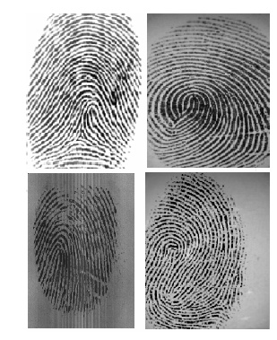 | Figure 4. Four images used for testing the SA |
The values of the capacities for embedding data by using the cover image and the four sets of range widths are given in Table 1.
5. Evaluation and Conclusions
If we look at the stego images distortion are imperceptible to our eyesight. So simply looking at stego image you will not get any idea about secret communication via image.The enhanced difference images are shown here to indicate the distortions resulting from the data embedding process. Distortions are found on the edges in the images. These distortions are less noticeable because changes in the edge parts of the images are generally less obvious to human eyes. Variable numbers of bits are embedded into the blocks of two pixels. It does not replace the LSBs of pixel values directly; instead, it changes the differences of the two pixel values in a block. We cannot find obvious suspicious artifacts on the resulting stego images by simple visual inspection. Resulting stego images using Range 1, Range 2 and Range 3 gives imperceptible results. Distortions are observed in stego images using Range 4, but these distortions are less as compared to conventional LSB replacement techniques. In comparison with LSB replacement method, the pixel value differencing method gives more imperceptible results.
References
| [1] | D. Kahn (1996). The history of steganography. 1st Information Hiding Workshop. Lecture Notes in Computer Science SpringerVerlag. 1174: pp. 1–5 |
| [2] | N. Johnson et al (1998). Steganalysis of Images Created Using Current Steganography Software. Proc. of the 2nd Information Hiding Workshop, Portland, Oregon |
| [3] | R. J. Anderson et al (1998). On the limits of steganography. IEEE Journal of Selected Areas in Communications (JSAC) – Special Issue on Copyright & Privacy Protection |
| [4] | S. Jajodia et al (1998). Steganalysis: The Investigation of Hidden Information", Proc. of the 1998 IEEE Information Technology Conference, Syracuse, New York |
| [5] | Soo-Chang, et al (2003). Hybrid pixel-based data hiding and block-based watermarking for error-diffused halftone images. In IEEE Transactions on Circuits and Systems for Video Technology. 13: pp. 867- 884 |
| [6] | Wu, D.C. et al (2003). A steganographic method for images by pixel-value differencing”, In Pattern Recognition Letters, 24 : 1613-1626 |
| [7] | Xinpeng, Z et al (2003). Vulnerability of pixel-value differencing steganography to histogram analysis and modification for enhanced security. In Pattern Recognition Letters, 25: pp. 331-339 |
 Abstract
 Reference
 Full-Text PDF
 Full-Text HTML