
-
Paper Information
- Paper Submission
-
Journal Information
- About This Journal
- Editorial Board
- Current Issue
- Archive
- Author Guidelines
- Contact Us
International Journal of Composite Materials
p-ISSN: 2166-479X e-ISSN: 2166-4919
2026; 16(1): 1-19
doi:10.5923/j.cmaterials.20261601.01
Received: Jul. 28, 2026; Accepted: Aug. 22, 2026; Published: Aug. 31, 2026

Ballistic Impact Study of Corrugated Core Filled Ceramic Composite Armor System
 Abstract
 Reference
 Full-Text PDF
 Full-text HTML
Shah Alam, Shriram Parmar
Department of Mechanical and Industrial Engineering, Texas A&M University-Kingsville, Kingsville, TX 78363, USA
Correspondence to: Shah Alam, Department of Mechanical and Industrial Engineering, Texas A&M University-Kingsville, Kingsville, TX 78363, USA.
| Email: |  |
Copyright © 2026 The Author(s). Published by Scientific & Academic Publishing.
This work is licensed under the Creative Commons Attribution International License (CC BY).
http://creativecommons.org/licenses/by/4.0/

This study focused on composite armor system behavior on ballistic impact. Armor is modeled with a sandwich-type structure consists of X shaped corrugated aluminum core with ceramics inserted in it. Skins of this structure are made up of fiber-reinforced composite Kevlar-29 and Ultra-high molecular weight polyethylene (Dyneema) and epoxy. An initial simulation is carried out for a single ceramic plate with 15 mm thickness impacted at bullet velocity 700 m/s, 800m/s, 900 m/s to select ceramic with better ballistic performance. Silicon carbide has shown significantly better ballistic impact performance than aluminum oxide, and silicon carbide is chosen as a ceramic material for further study. To simulate impact behavior of composites armor under different impact velocities, a finite element model was created using Abaqus software. Various parameters like kinetic energy, residual velocity, and energy-absorbing capacity are studied for impact velocities starting from 700 m/s to the velocity bullet penetrating armor. Different composite armor compositions have shown different behavior for different velocities. Energy absorption capacity is increased for composite armors with 2 mm, 3mm, and 4 mm front and backed layer as an increase in facing and backed layer thickness. Validations of the finite element model are conducted for composite with Kevlar-29 and aluminum oxide composition using experimental result done by other authors in our lab. Results for the various combinations of composite layup on the impact of different velocities are discussed and combination of Kevlar-29/epoxy with silicon carbide showed better ballistic performance for all impact velocities.• Sandwich armor designed with X type core filled with ceramic and skin with dyneema. • Impact properties determined using finite element analysis. • Silicon carbide is found to be better than aluminum oxide. • Kevlar-29/epoxy with silicon carbide showed better ballistic performance. • Validations of FE results conducted using experimental testing.
Keywords: Ballistic impact, Armor, Composite, Dyneema, X-shaped core
Cite this paper: Shah Alam, Shriram Parmar, Ballistic Impact Study of Corrugated Core Filled Ceramic Composite Armor System, International Journal of Composite Materials, Vol. 16 No. 1, 2026, pp. 1-19. doi: 10.5923/j.cmaterials.20261601.01.
Article Outline
1. Introduction
- The armor technology was used from ancient times during the war, where horses and warriors wore it to defend themselves. At that time, armors were mainly made using bamboo, leather, cloth, and metal chains. Soldiers have worn body armor to protect themselves on the battleground. People have often wanted greater staff security, from leather and chain mail. In recent years, the design of composite armor has been changing as technologies are developing every decade [1]. World technology is advancing to model composites having uniform weight, high toughness compared to their weight, which can be used for various functions, can also be easily manufactured [2]. The goal of human lightweight body armor construction has always been to produce lighter and more rigid components so that protection can be improved while reducing weight. The introduction of synthetic fibers has accelerated advancement in this area. The armors tend to have good penetration protection, energy absorption, and damage containment. The composite armor technology is widely used in bulletproof jackets, helicopters, tanks, and marines, where lightweight applications are required against bullet piercing [3-5]. Lightweight armor material could help decrease kinetic energy of penetrator; to achieve this, the ballistic performance of various lightweight materials is studied, and aluminum is found to be a better lightweight material [6]. Since human progress, the chances of war clashes have been portrayed by the steady development of weapons and armor. New materials are currently being studied and designed to protect against single high-velocity bullets and multiple bullet impacts, explosive devices, and explosive fragments [7]. In a sandwich type composite armor system, the core with ceramic materials is stacked between these two facing and backed layers. As stress waves interact with materials with varying mechanical properties, they appear to lose energy. It is due to wave propagation, which is directly proportional to density and elastic modulus. As a result, most modern armors are multilayered armors systems, with fiber-reinforced high strength plastics and ceramic constructing their laminated composite layered parts [9]. For most multilayer composite armor systems, ceramics are used as the front layer that is striked first. Ceramics were introduced to armor designers' notice because of their high stiffness, rigidity, and compression strength, making them effective at blunting and fracturing impeding bullets. Aluminum oxide (Al2O3) and silicon carbide (SiC) are the most often used ceramics. The ballistic performance increases as the ceramic are used as a striking layer and followed by the backplate because of higher lateral restrictions at the damaged location. On the other hand, the projectile will damage the entire ceramic layer, whereas the damage is small and only affects the tiles in the surrounding area for small blocks [10].Ceramics are primarily taken in hexagonal patterns or rectangular patterns separated by a thin wall between them. A thin wall between hexagonal ceramic patterns restricts the shock wave and cracks propagation across the boundaries. The primary function of the intermediate layer is to support the front ceramic layer. Sometimes intermediate layer also functions as a backed layer. The most used materials for the intermediate layer are UHMWPE and aramid fabric laminates with epoxies. After glass fiber and aramid fiber, UHMWPE is a third-generation fiber with high strength, high modulus, and low density for projectile resistance. This fiber offers excellent protection against small fragments and bullets and is, hence, widely used in various types of personal protection products [11].The typical sandwich type composite structure has a center core, and this core is supported by front and back by same sequence of components made of similar materials. Skins are widely used in sandwich-type composite armor systems for front and back layers and multilayer composites for striking faces. Skins may be metallic or non-metallic, but non-metallic skins are preferred over metallic skins since they are lightweight of corrosion resistant [12]. The cores are sandwiched between two skins at the front and backed layer of composites. Core itself is a lightweight composite component whose primary function is to support the structure of composite armor against buckling and shear loads. They are lightweight components that have very high strength as compared to their weight. An increase in core thickness can result in a more significant improvement in all properties than a lesser increase in weight. The core can also be stuffed with ceramic materials to improve its functionality [13]. The honeycomb core is formed by a hexagonal panel sandwiched between plates. The desirable properties of this core panel can be achieved by adjusting the thickness and height of the panel. The honeycomb core structure is highly utilized in applications with very high damping, flexural rigidity, and weight constraints [14]. The adhesive is an essential element of composite armor systems, and they are applied between two layers. Their primary function is to keep the whole structure as a single body before and after impact and simultaneously absorb tensile and shear stresses [15]. An experimental testing [16] is carried out for multilayer composite armor in which fique fabric epoxy is faced by ceramics and backed by aluminum plate. High velocity projectile is impacted on composite multilayer armor, and the ballistic performance is calculated based on back face signature. Ballistic performance is carried out for 4 samples of multilayer armor consisting of different volume fractions of fique fabric epoxies viz: (i) Epoxy-15%Fique Fabric (ii) Epoxy-30%Fique Fabric (iii) Epoxy-40%Fique Fabric (iv) Epoxy-50%Fique Fabric. After the experiment, back face signature (BFS) values are calculated using Weibull analysis, and BFS values calculated are 20 mm, 21.60 mm, 21 mm, and 23.30 mm, respectively. In another study [17], actual testing and FEA simulations are carried out for a specific sequence of composite materials, and results are studied with and without constraining the boundary locations. The projectile is fired from 593.5 cm with a velocity of 825 m/s. FEA simulation is carried out in ANSYS/ LS-DYNA. After testing and FEA simulations, ceramic plate damage, backplane deformation of each layer, energy histories, damage distribution diagrams are discussed. It was discovered that the TC4 transition plate provides more excellent strength protection for the ceramic layer. In research [18], ballistic performance is simulated for composite armor with aluminum oxide and ultra-high molecular weight polyethylene (UHMWPE). Two cases were studied for FEA analysis; in case 1, the alumina plate is kept on the striking face, followed by the UHMWPE plate, and for case 2, the position is reversed. Test plates are constrained at all four edges, and the projectile is made to strike at a velocity of 800 m/s. The study has concluded that a hybrid combination with a UHMWPE plate facing projectile has a higher energy absorption capacity. In a study [19], the multilayer composite armor is designed using the appropriate properties of materials used for each layer. A ceramic facing plate is followed by a ductile backing plate with good fracture toughness and bending strength to overcome this. Ballistic deformation was found to be lower than 44mm according to MIL-PRF- 46103 norms. The research [20] explains various benefits of thickness parameters of adhesive layers after studying the single ceramic plate backed by aluminum and double ceramic plate supported by aluminum with variable epoxy adhesive layer thicknesses. It is experimentally found that ceramic fracture size is decreased as adhesive thickness increases. In a study [21] the findings of comprehensive ballistic performance of various ceramics are presented. Ceramics' performance is considered based on the structure, properties, and features of armor system design. In the study [22], the ballistic impact on Twaron is simulated using the finite element method. The ballistic limit, energy absorption, residual velocity, and transverse deflection patterns are anticipated and compared to those obtained in the test results. In research [23], a mosaic ceramic plate (MCA) as facing plate, biomimetic tendon reinforced (BTR) as the backplate, and streamlined link network supporting design is studied. This research includes simulated prototyping and ballistic testing results for evidence of the most recent armor design and methodology. The study in literature [24] investigated the response of armor for high velocity strikes on the composite surface. Actual impact testing is performed using a gas gun system used to fire a penetrator made up of steel at a velocity of 610 m/s. The kinetic energy, energy absorbed, stress distributions across layers, and damage of each layer are calculated. These results are correlated with actual testing, and results are found closer to simulation outputs. In research [25], Laminate and textile composites are compared for impact performance by simulation and experimental test. The impact loss mechanism of composites is studied using a combination of damage and energy development behavior. It is found that laminated composites possess more resistance and more damage for ballistic impact than textile models. In reference [26], the ceramic-faced composite armor is studied for aircraft use, and it is found that the carbon fiber reinforced plastic front panel in composite improves the bending strength by a factor of three. Also, after a ballistic impact, the proposed device will display considerable structural stability, offering the device ballistic protection. In a study [27], an experimental method was used to measure both elastic and fracture properties of PVC foams featured by different densities, ranging from 100 to 200 kg/m3. The parameters experimentally determined are subsequently employed as input values into a numerical model previously developed. The work included the compression and fracture tests. The numerical investigation aimed to simulate crack propagation in PVC foam. In another study [28], a nonlinear approach to investigate the behavior of composite sandwich structures with transversely compressible core, under static and dynamic loading conditions were investigated. The proposed model in the 2D framework incorporates moving mesh cohesive modeling, crack initiation and nucleation at core/skin interfaces. Interface elements were used to predict debonding mechanisms, whereas shear deformable beams and two-dimensional plane stress elements identify skin and core behavior, respectively. Interfacial crack onset, layer kinematic and debonding propagation effects were correctly simulated. The moving mesh technique ensured a reduction of the computational costs, required to predict crack onset and progressive evolution of debonding phenomena. Cohesive models for sandwich core/skin interfaces were calibrated by means of comparisons with numerical and experimental data with respect to mode I and mode II configurations.A numerical model based on moving mesh strategy is proposed to simulate the evolution of internal material discontinuities in a continuum medium [29]. The approach combines concepts arising from structural mechanics and moving mesh methodology, which are implemented in a unified framework to predict crack growth on the basis of Fracture Mechanics variables. Moving computational nodes are modified starting from a fixed referential coordinate system on the basis of a crack growth criterion to predict directionality and displacement of the tip front. Reviewing all above research papers, very little research was found used sandwich type composite armor in which aluminum x core filled with ceramic and backed by FRP skins like Kevlar-29/epoxy or UHMWPE as facing and backed layer were used. Therefore, in this study different combinations of these materials with the aluminum corrugated x core armor structure for impact behavior are studied. The main objective of this research is to improve the impact resistance of the composite armor against high-velocity steel bullet with different combinations of the facing layer, backed layer and core ceramic materials by trying different combinations of Kevlar-29 and UHMWPE as a facing material and aluminum oxide (Al2O3) or silicon carbide (SiC) as ceramics. These armor structures are impacted by a bullet is simulated for different facing layer thicknesses with a different striking velocity of the bullet. All these finite element analyses are carried out using the finite element analysis software Abaqus CAE. The model is validated comparing the results with another study. The outline of the paper is as follows. Section 2 presents the material and methods and validation model, whereas in Section 3 the numerical results and section 4 conclusions.
2. Materials and Methods
- The numerical analysis of composite armor is carried out using commercial software Abaqus. The simulation consists of some steps, which involve creating the geometry of the parts, applying material properties, applying load and boundary conditions, creating contacts, running the model, determining the optimum energy absorption of the structure, the ballistic limit, and residual velocity of the impactor. The steps carried out in finite element simulations are as discussed below.
2.1. Finite Element Modeling
- In this study, sandwich-type composite armor is analyzed. It consists of a core supported by a facing and backed layer. The core is made up of X shaped aluminum structure with ceramic tiles inserted into it. The facing and backed layer comprise fiber material like Kevlar and ultra-high molecular weight polyethylene with epoxy.
2.1.1. Facing and Backed Layer
- The facing and a backed layer of composite armor can also be called top skin, and the bottom skin is modeled with Kevlar-29 and UHMWPE. The part is created by creating a 3D deformable part using extrude command in part module 120 mm x 120 mm with variable thicknesses 2 mm, 3 mm, and 4 mm. The part with the desired thickness is partitioned in several layers with 0.5 mm thickness plies, and the number of plies considered is 6, 8, and 10 for 3 mm, 4 mm, and 5 mm Kevlar panel thickness, respectively. The orientation for Kevlar-29 and UHMWPE skin plies is considered [0/90]s depending on the number of plies and skin thickness. After modeling the properties assigned for a composite layup as continuum shell in a laminate module, the desired thickness, material, and orientation are given for respective plies. The laminate of composite layup for skin is as shown in figure 1.
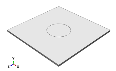 | Figure 1. Facing and backed layer |
2.1.2. Aluminum Core Frame
- Corrugated X core is created using a deformable 3D deformable shell module as shown in figure 2. Aluminum (Al6061-T6) is used for X shape corrugated core. The primary function of the core is to support facing and backing along with ceramic blocks within it. The corrugated structures help the composite to withstand bending and high-velocity impacts. The 3 mm thick armor core is made with X – shape 120 mm x 120 mm dimensions with height of 20 mm.
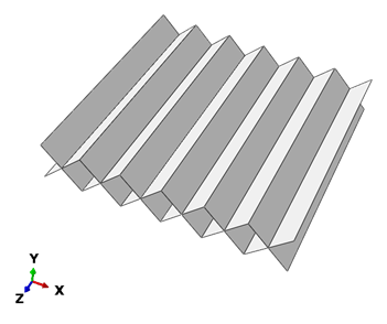 | Figure 2. X-shape corrugated core |
2.1.3. Ceramic Blocks
- The empty spaces between X - structure aluminum core are filled with ceramic blocks. The ceramics used in this analysis are Aluminum oxide and silicon carbide. The cross-section of ceramic blocks is square and triangular (exact half of the square cross-section), with diagonals, 20 mm, and sides equal to 14.14 mm. For triangular blocks, side with 14.14 base 20 mm. These blocks are extruded along the width of the composite panel, i.e., 120 mm. The aluminum core filled with ceramic block is as shown in figure 3.
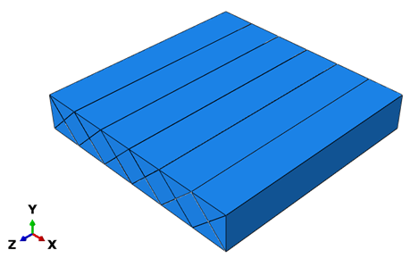 | Figure 3. X Core filled with ceramic blocks |
2.1.4. Impactor - Steel Bullet
- The impactor used in this simulation is a steel bullet. The bullet is designed with an overall length of 19 mm, including 10 mm cylinder height and 9 mm conical height with a diameter of 8 mm. It is assigned with steel material with an overall mass of 5.8 g. The bullet is assigned with undeformable rigid body constraint to get it penetrated through the composite. The reference point for the impactor is assigned at the bullet's tip, with velocity given at the same point. Figure 4 shows the bullet used in the analysis.
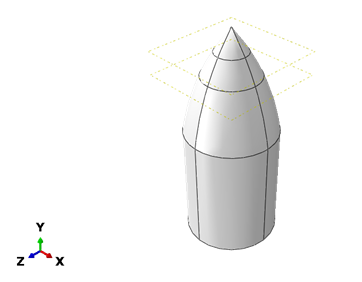 | Figure 4. Impactor- steel bullet |
2.1.5. Assembly
- All components are assembled in the Abaqus assembly command. The parts are assembled in a sequence as facing layer, core, and backed layer. The bullet is kept around 2 mm to 3 mm from the facing layer to initiate impact velocity. Figure 5 shows complete assembled components for the simulation.
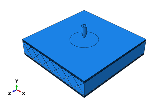 | Figure 5. Composite armor assembly |
2.2. Material Properties
- The materials used in the model has different failure criteria according to the nature of the material like ductile, brittle, composites. The material properties are assigned to each material accordingly in Abaqus. The modeling of Kevlar-29/epoxy and UHMWPE follows hashin damage criterial in finite element modeling in abaqus. The meterial properties for Kevlar-29/epoxy [30] and UHMWPE [31] are used. As aluminum is ductile material, Johnson Cook material damage model used for deformation of aluminum in this simulation. The material properties considered for aluminum in this study [32] are used. For ceramic materials, damage criteria for brittle material is used. For the simulations, Johnson Holmsquist-2 (JH-2) damage model is considered. The JH-2 property parameters for ceramics [33,34] are used. The impactor in this study is steel bullet. The material properties of steel [35] are used in this study.
2.3. Composite Layup
- The facing and backed layers of the composite consist of various layers of fibers. The desired thickness of the composite layer is achieved by stacking several 0.5 mm thick fiber layers. The 4 mm, 3 mm, and 2 mm thick fiber layup plies are 8, 6, and 4, respectively. For simulation first, the plate of desired thickness is modeled and partitioned in terms of 0.5 mm thickness. The material properties and fiber orientation are assigned composite layup in the property module. For the UHMWPE/polyurethane and the Kevlar-29/epoxy, the fiber orientation of [0/90]2 is used.
2.4. Interactions
- The interaction needs to be assigned between all the components of composite armor assembly to make them stuck together during the application of external forces. Interaction is given between the impactor bullet and composite layup to define the behavior of the composite while the bullet penetrates through it. The tie contact is assigned between core surface and top layer and bottom layer surfaces of composite. Tie contact is also assigned between surfaces of ceramic blocks and aluminum core. Surface to surface interaction between bullet and composite is assigned by selecting bullet surface as a master surface and set of nodes around impact area on composites from the top layer, aluminum core, ceramic blocks, and bottom layer as slave surface.
2.5. Boundary Conditions
- Boundary conditions are assigned to constrain the movement of the component in certain directions as required. As shown in figure 6, the edges of the composite armor top and bottom layers are fixed in all six degrees of freedom to sustain high velocity bullet impact loads. The other components of composite armor are attached to these layers. Boundary conditions are applied for the initial step through the load module.
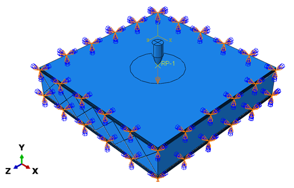 | Figure 6. Boundary conditions |
2.6. Load
- For the simulation, the velocity is assigned to the impactor in one direction. The velocity is assigned in the load module in the predefined module. The movement of the impactor is restricted in two translational and three rotational directions except in Y-axis, in which the velocity is assigned. In this simulation, the velocity is applied in a negative Y-direction. The various velocities are changed to run different iterations and compare parametric studies for each iteration.
2.7. Mesh
- Various parts in the composite panel meshed with different procedures. Meshing is a process where we subdivide the CAD model into finite elements for which a set of equations are solved. For this composite, each part of the assembly has meshed individually with different techniques. The meshing is carried out in a mesh module. The center part of the model meshed with smaller element sizes since it is the most crucial part of the model due to its high-velocity impact. The other location than the impact location, has meshed with coarse mesh. Different strategies are used to mesh the various components. The skin is made up of composite layup meshed with hexagonal continuum shell elements with a fine element size of 1 mm at the center and coarse elements with 3 mm towards the edges. The aluminum X shape core is modeled with 2D shell elements. The meshing is done with quadratic 2-D elements with a 1 mm mesh size throughout the part with an assigned desired thickness of 3 mm. The element size kept the same throughout because these are 2D elements, and the number of elements does not significantly affect simulation run time. The ceramic cores are modeled with 3D hexagonal elements. The ceramic blocks at the center of the mode have meshed with 1 mm size, and other tiles are modeled with 3 mm size. The bullet has meshed with hexagonal elements with fine mesh at the tip and coarse mesh in other parts. The meshed model for the assembly and individual components is shown below from figure 7.
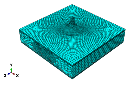 | Figure 7. Mesh model of armor assembly |
2.8. Mesh Convergence
- The mesh convergence is achieved by decreasing the mesh element size and analyzing the results at different mesh sizes. Generally, a finer mesh of the part tends to be more accurate of the simulation. But for more significant parts, more accuracy with more elements and nodes will take more run time and data storage space. A mesh convergence study is carried out at the beginning to optimize the balance between run time and accuracy. In this research, the mesh convergence is carried out by plotting residual velocities against different mesh sizes 1.4 mm, 1.2 mm. 1.0 mm, and 0.8 mm using a Kevlar-29/epoxy panel thickness of 3 mm, and impact is carried out at an impact velocity of 400m/s. The variation of results between the 1.0 mm to 0.8 mm mesh size was around 1%, so mesh convergence for these mesh sizes is said to be confirmed.
2.9. Failure Mechanism
- The knowledge of damage or failure due to sudden impact loads is important in finite element analysis. This study used various materials like fiber-reinforced materials, brittle materials like ceramics, and ductile metals like aluminum. Each different type of material uses different failure and fracture mechanisms during deformation. All these failure mechanisms are discussed below.
2.9.1. Failure Mechanism for Ductile Materials
- Aluminum, copper, titanium alloys are ductile in nature. On application of tensile loading, the material deformation follows the stress train curve. When the tensile loads are within the elastic limit, the metal will regain its original shape and dimension. When stresses applied are beyond an elastic limit, it will start permanent deformation in the body, and further continuous application of loads will lead to fracture of the metallic body. This kind of failure was observed for the aluminum corrugated core structure [36]. The Johnson-Cook plasticity deformation model is used for ductile metals to define that fracture mechanism in finite element simulation software.
2.9.2. Johnson-Cook Model
- The Johnson-Cook plasticity theory is well adapted to modeling metal distortion at high strain rates. This is a kind of Mises plasticity that incorporates analytical formulations of the hardening rule and rate dependency. In an adiabatic transient dynamic simulation, it is commonly utilized. An utterly plastic material or work hardening can be specified in Abaqus. Both Abaqus/Standard and Abaqus/Explicit support isotropic hardening, including Johnson-Cook hardening. Abaqus also offers kinematic hardening for materials that are exposed to cyclic stress. Johnson-Cook hardening is an isotropic hardening process in which the static yield stress, 0, is of the form [37].The stress in the Johnson-Cook model is defined as follows [37].
 Here,
Here,  = equivalent stresse = equivalent plastic strain
 = equivalent plastic strain rateMaterial constants are, A= yield stress of the materialB= strain hardening constantn= strain hardening coefficientC= strengthening coefficient of strain ratem= thermal softening coefficient
  and
and  is calculated by,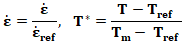
2.9.3. Damage criteria for brittle materials
- Brittle materials exhibit higher compressive strength and low tensile strength like ceramics, concrete, and rock. These materials show progressive damage under the application of loads due to the growth of microfractures. In the 1990s, Gordon R. Johnson and Timothy J. Holmquist defined damage in brittle materials, mostly like ceramics under basically delivered loads. Johnson Holmquist 1 (JH-1) and Johnson Holmquist 2 (JH-2) models were developed by them. The JH-2 model is considered a more accurate model which accounts for progressive damage and deformation [38]. The strength is given in terms of stress [38],
 Here,
Here, = intact equivalent stressD = damage variable
 = fractured equivalent stressThe stress at Hugoniot elastic limit (HEL) is given by,
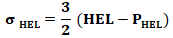 PHEL = Pressure at HELThe strength equation can be written as,
 The JH-2 model [38] assumes that the strength equation may be stated as a function of pressure and strain rate in the case of undamaged and totally damaged material states, respectively.
 The material parameters are A, B, C, M, and N in the above equation.The normalized pressure is given by,
 The normalized maximum tensile hydrostatic pressure is given by,
 The JH-2 model uses a similar damage accumulation of the Johnson-Cook model and assumes that the damage increases along with the plastic strain as follows
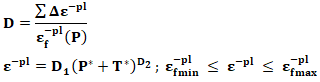 For brittle material, the relation between pressure and volume is given by,
 Here, K1, K2, and K3 are material constantsIf material is failing, the additional pressure increment
  is added as below.
2.9.4. Hashin Damage Criterion
- This criterion is designed by Hashin and Rotem mainly specifically for fiber reinforced polymers. Fiber breaking in tension, fiber buckling compression, matrix cracking in tension, and matrix crushing compression are all examples of material damage processes recognized by these criteria.For four failure modes following equations apply [39]
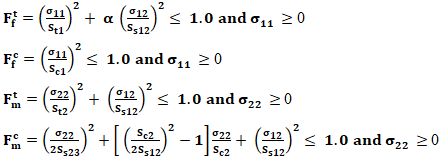 If one of these indexes
  and
and  surpasses the unit value, the damage initiation criterion is met in one of the failure mechanisms, and the stress state in a material point is assessed by formula,
 Here,
Here,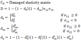 In the above equation, σij, τij, εij and γij (i, j = 1, 2) are stress and strain in normal and shear directions; Eij, vij and G12 are Young’s modulus, Poisson’s ratio and shear modulus in respective directions; wij is the parameter quantify the corresponding damage in each direction, which varies from 0.0 to 1.0.
2.10. Model Validation
- The model created in this study is comprised of multiple sandwich panels with different geometry. No literature merged geometric components in a way that was like the model employed in this study. As a result, no numerical or experimental work can be utilized to directly support the sandwich configuration results. However, to validate the outcomes of these models, this study looked at residual velocity by separate components and compared it to reliable literature with empirical observations [31]. The materials used in this research are Kevlar-29 and UHMWPE as skin materials and aluminum oxide and silicon carbide as ceramic materials. A similar study is found for the material combination of Kevlar-29 laminates and the Al2O3 as a ceramic. For which the experimental testing is carried out. The Kevlar-29 material used in this literature is the same as the one used in this research, and the ceramic in the literature is aluminum oxide 99.7%. The Finite element simulation is carried out to conduct validation in Abaqus CAE 2017. The modeling of the composite is carried out in the same way as in the experimental setup. The impactor used in this validation is modeled with a steel core part with a non-deformable steel element. The von Mises stress distribution for impact velocity 1070 m/s is shown in the figure 8.
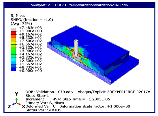 | Figure 8. Von Mises stresses (MPa) for validation model |
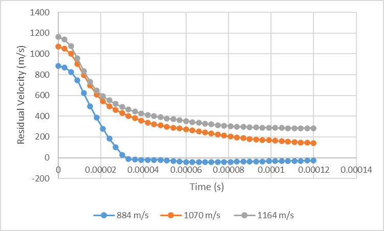 | Figure 9. Residual velocity plots for validation model |
|

3. Numerical Results and Discussions
3.1. Finite Element Modeling
- The performance of the composite armor is analyzed using finite element simulation software Abaqus CAE 2017. The base model of the composite armor system is prepared with facing and backed layer thickness of 3 mm and core thickness of 20 mm with an X-shaped corrugated core. This base model is assigned with different materials for facing, backed layer, and ceramic material and carried out the parametric study for these elements.
3.2. Result Comparison for Silicon Carbide and Aluminum Oxide as Core Materials
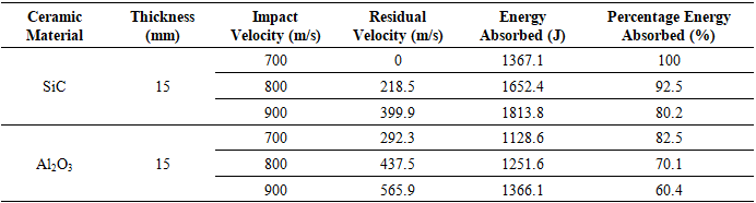
- For the selection of ceramic material, in the beginning, the impact analysis for 15 mm ceramic plates is conducted to compare the ceramic’s response against high-velocity ballistic impact. Both ceramic plates are modeled with dimensions 120 mm x 120 mm and 15 mm thick. The silicon carbide is sharper and brittle than aluminum oxide, which makes it withstand higher velocity impacts. The simulations are started with 500 m/s bullet impacts to ensure the ballistic limit of the ceramics. The bullet is fully penetrated through the aluminum oxide (Al2O3) ceramic plate and is completely stopped in a ceramic plate made up of silicon carbide (SiC) at 700 m/s impact velocity. The impactor is fully penetrating through the plate for the impacting bullet at 800 m/s and 900 m/s. The performance of both materials is compared based on kinetic energy, residual velocity, and energy absorption capacity. The von Mises stress distribution is shown in figures 10, 11, and 12. The stress distribution is shown at the time step of 15 microseconds. The unit of stress in all plots is MPa.
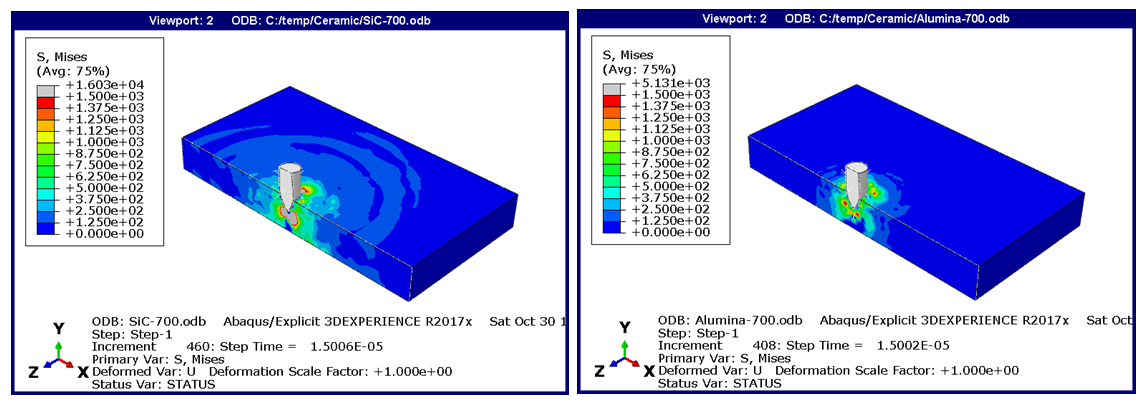 | Figure 10. Von Mises stress distribution SiC (left) and Al2O3 (right) at 700 m/s |
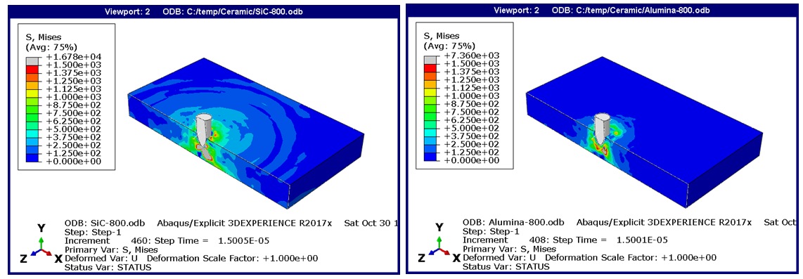 | Figure 11. Von Mises stress distribution SiC (left) and Al2O3 (right) at 800 m/s |
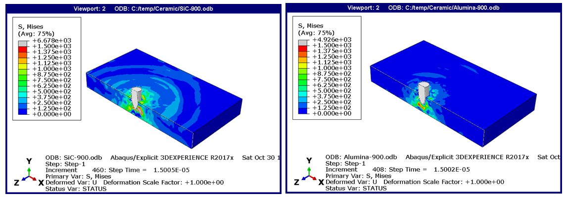 | Figure 12. Von Mises stress distribution SiC (left) and Al2O3 (right) at 900 m/s |
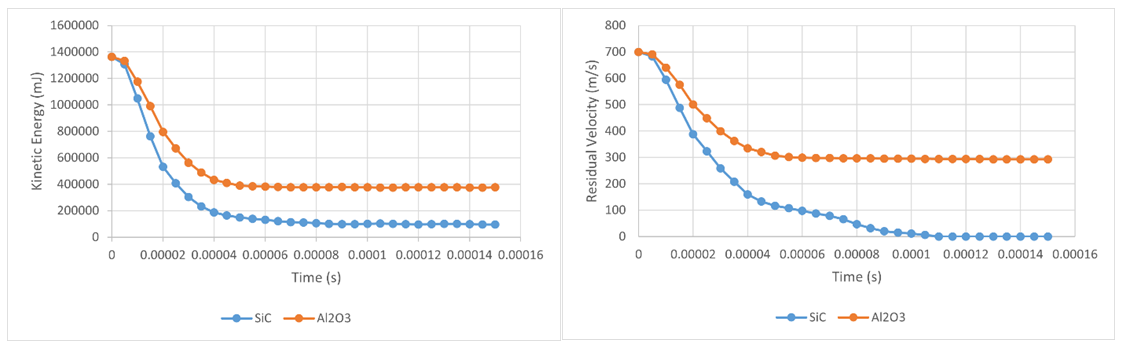 | Figure 13. Kinetic energy and residual velocity plots for 700 m/s impact velocity |
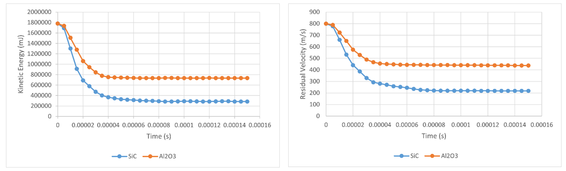 | Figure 14. Kinetic energy and residual velocity plots for 800 m/s impact velocity |
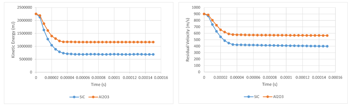 | Figure 15. Kinetic energy and residual velocity plots for 900 m/s impact velocity |
|
3.3. Results for Composite Armor
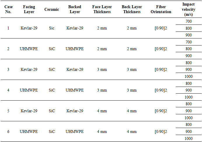
- The final model of sandwich-type composite armor is modeled with the silicon carbide as a ceramic material. The ceramic tiles are inserted corrugated aluminum core, and this centerpiece is sandwiched between front and back layers. The simulations carried out for different material compositions are shown in the table 3.
|
3.3.1. Composite armor with 2 mm skin
- The figures below show the von Mises stresses for the impact velocities 700 m/s, 800 m/s, and 900 m/s. It is observed that the von Mises stresses are maximum at the impact location for a particular step time. As the impact begins, the bullet starts penetrating through the composite, and the location for the maximum von Mises stresses is changed accordingly. The von Mises stresses are shown in the figure 16- figure 18 at the time step of 15 microseconds.
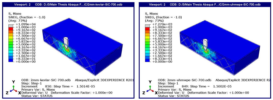 | Figure 16. Composite with 2 mm Kevlar-29 skin (left) and UHMWPE (right) at 700 m/s |
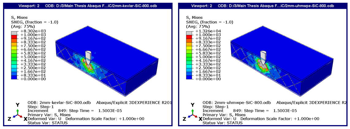 | Figure 17. Composite with 2 mm Kevlar-29 skin (left) and UHMWPE (right) at 800 m/s |
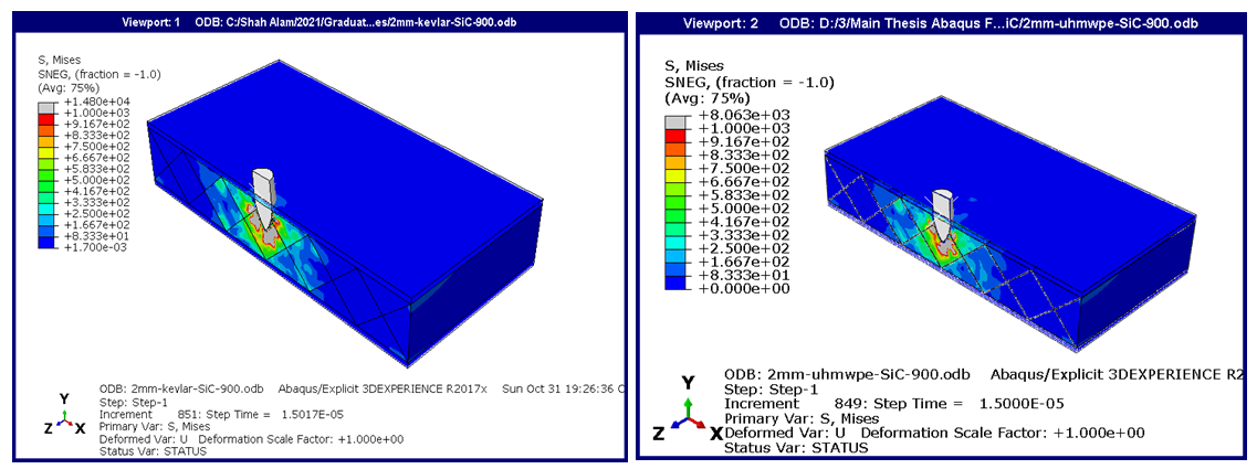 | Figure 18. Composite with 2 mm Kevlar-29 skin (left) and UHMWPE (right) at 900 m/s |
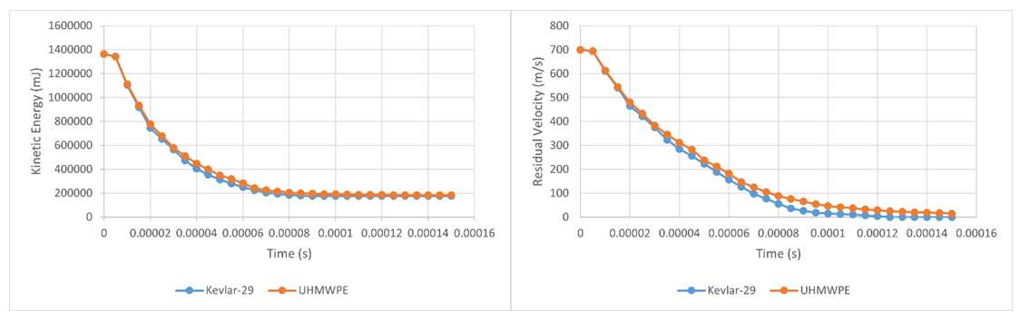 | Figure 19. Kinetic energy and residual velocity plots for 2 mm skin - 700 m/s impact velocity |
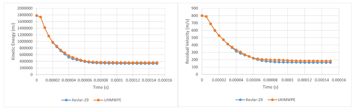 | Figure 20. Kinetic energy and residual velocity plots for 2 mm skin - 800 m/s impact velocity |
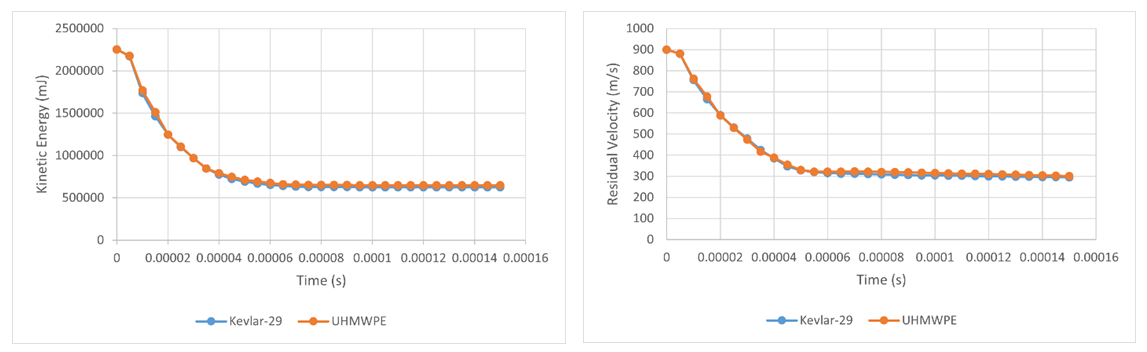 | Figure 21. Kinetic energy and residual velocity plots for 2 mm skin - 900 m/s impact velocity |
3.3.2. Composite Armor with 3 mm Skin
- The thickness of the facing and baked layer increase by 1 mm for this composition, and the model is simulated with a skin thickness of 3 mm. The overall performance of the composite panel is improved for this combination compared to the composite panel with 2 mm thickness. The figures below from figure 22 to figure 24 show the von Mises stress distribution for both composite layers at impact velocities of 800 m/s, 900 m/s, and 1000 m/s. As the residual velocity of the bullet was zero for impact velocity of 700 m/s and 800 m/s, the study for impact velocities 800 m/s, 900 m/s, and 1000 m/s is explained.
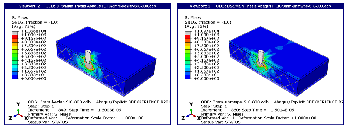 | Figure 22. Composite with 3 mm Kevlar-29 skin (left) and UHMWPE (right) at 800 m/s |
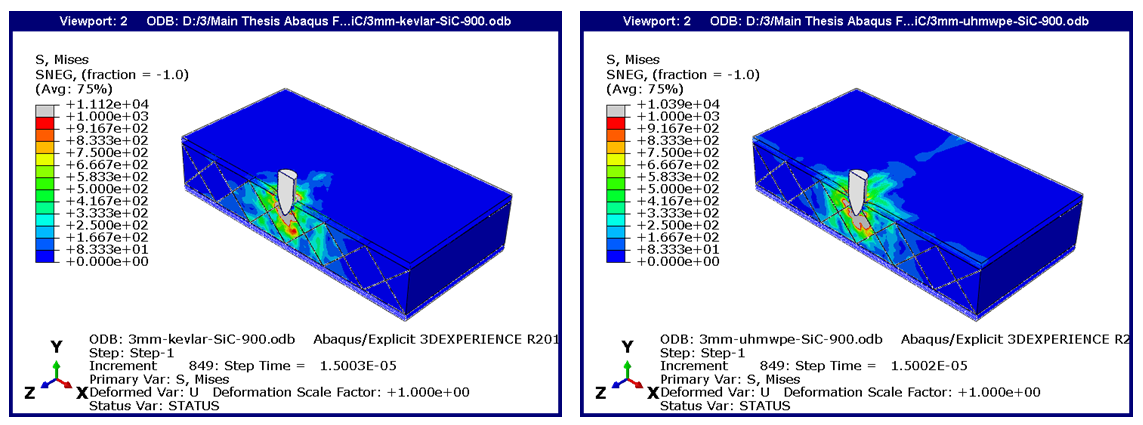 | Figure 23. Composite with 3 mm Kevlar-29 skin (left) and UHMWPE (right) at 900 m/s |
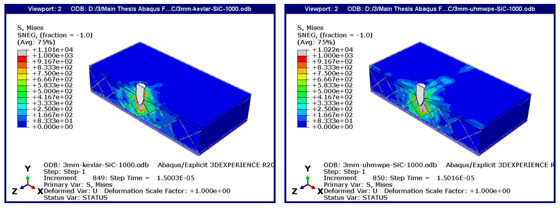 | Figure 24. Composite with 3 mm Kevlar-29 skin (left) and UHMWPE (right) at 1000 m/s |
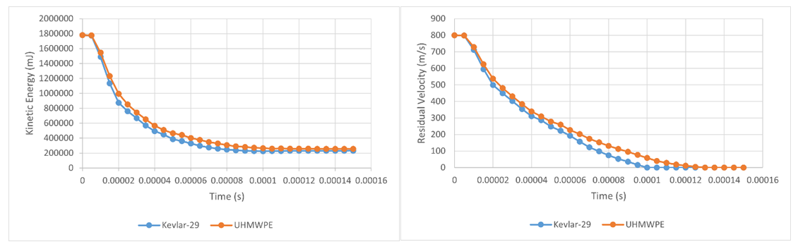 | Figure 25. Kinetic energy and residual velocity plots for 3 mm skin - 800 m/s impact velocity |
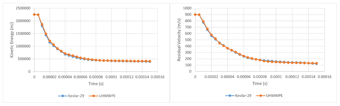 | Figure 26. Kinetic energy and residual velocity plots for 3 mm skin - 900 m/s impact velocity |
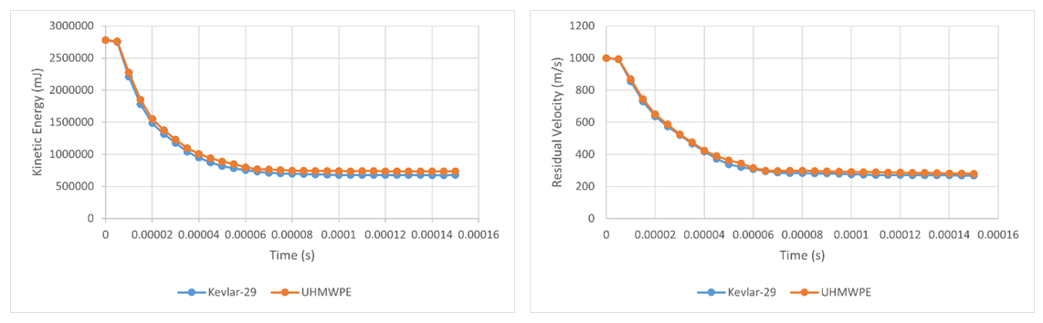 | Figure 27. Kinetic energy and residual velocity plots for 3 mm skin -1000 m/s impact velocity |
3.3.3. Composite Armor with 4 mm Skin
- The simulation is carried out for composite with 4 mm thick skin. As the skin thickness is more in this composition, the performance is observed better than previous compositions. The bullet is impacted at a velocity of 800 m/s, 900 m/s, and 100 m/s. The von Mises stress distribution for these simulations is shown in the figures 28-30.
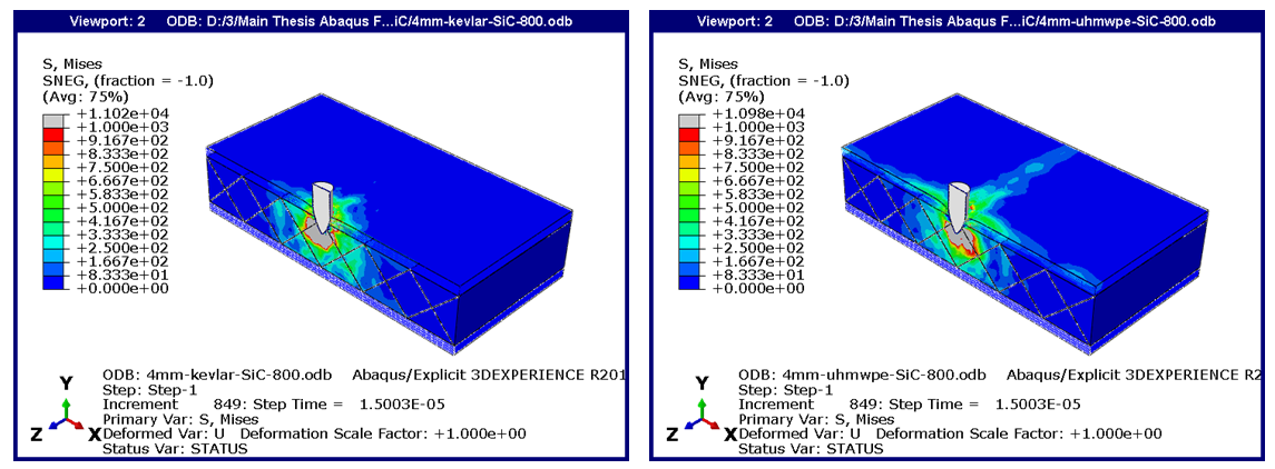 | Figure 28. Composite with 4 mm Kevlar-29 skin (left) and UHMWPE (right) at 800 m/s |
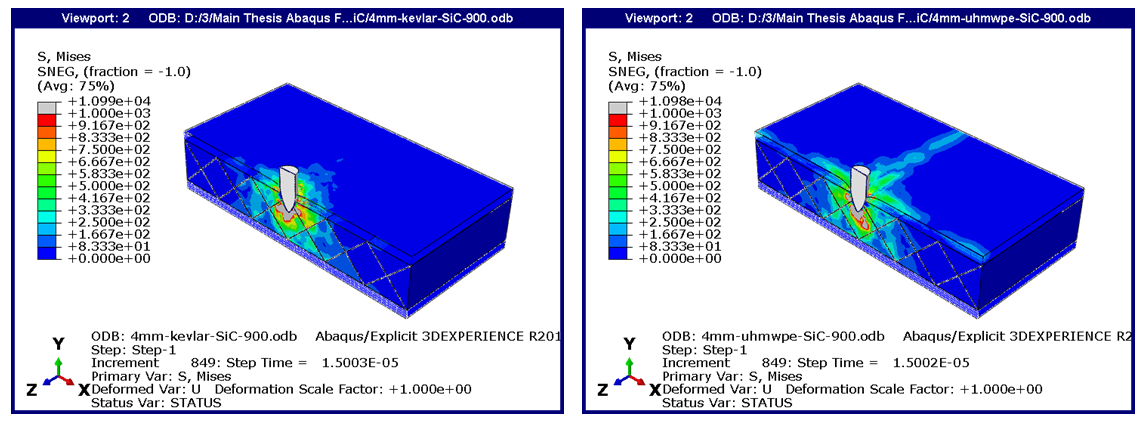 | Figure 29. Composite with 4 mm Kevlar-29 skin (left) and UHMWPE (right) at 900 m/s |
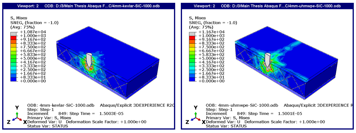 | Figure 30. Composite with 4 mm Kevlar-29 skin (left) and UHMWPE (right) at 1000 m/s |
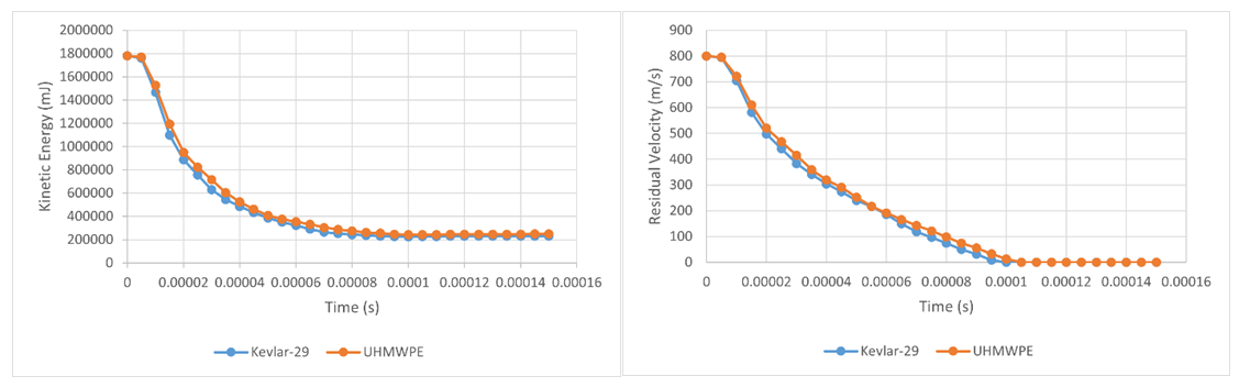 | Figure 31. Kinetic energy and residual velocity plots for 4 mm skin - 800 m/s impact velocity |
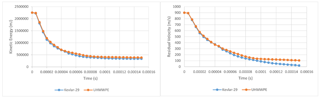 | Figure 32. Kinetic energy and residual velocity plots for 4 mm skin - 900 m/s impact velocity |
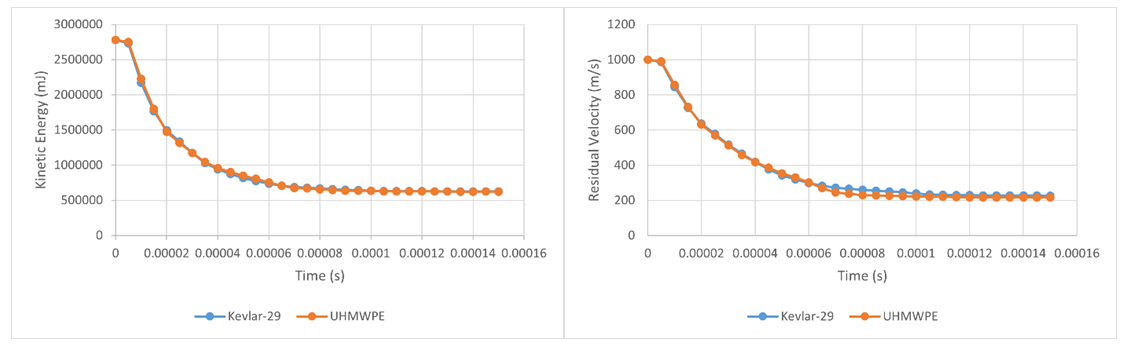 | Figure 33. Kinetic energy and residual velocity plots for 4 mm skin - 1000 m/s impact velocity |
3.4. Energy Absorption
- The energy is absorbed within the composite during the bullet impact. The maximum energy is absorbed when the residual velocity of the bullet is minimum. In this study, the energy absorbed is calculated by the formula below. It is basically the difference in kinetic energy at impact and residual kinetic energy.Energy Absorption
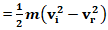 Here,m = bullet mass,
 = impact velocity of the bullet
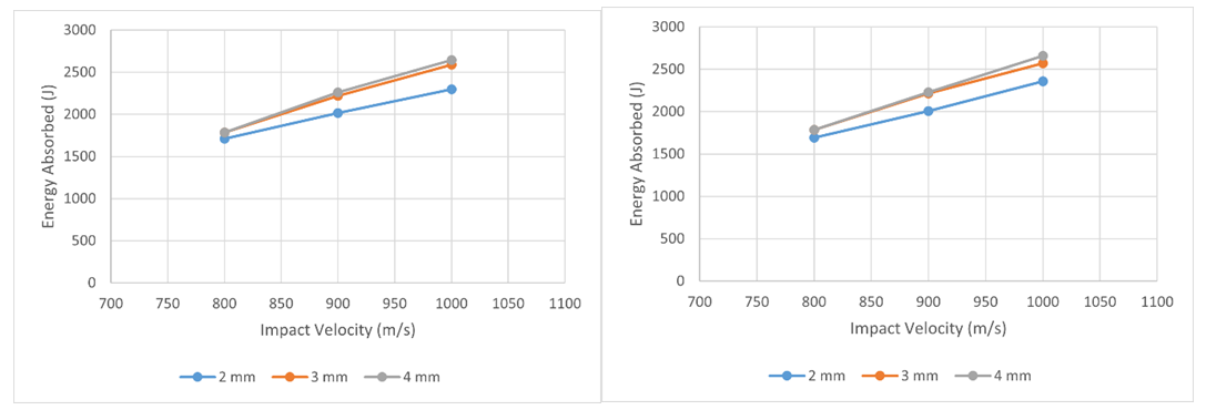
  = residual/final velocity of bullet The energy absorbed by Kevlar-29 and UHMWPE facing layers with different thicknesses and impact velocities is shown in figure 34. The residual velocity of the impactor decreases as an increase in the facing and backing layer thickness for the same velocity impact. Due to this, the energy absorbed is increased with increased facing and backed layer thickness.
  | Figure 34. Energy absorbed Kevlar-29 skin (left) and UHMWPE skin (right) |
3.5. Ballistic Performance of the composite Armor Summary
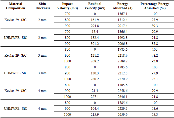
- The table below shows the summary of all simulations carried out for complete armor with x-core filled with ceramic and skins. The performance of the composite armor is studied in terms of the residual velocity, energy absorption for all combinations, and percentage of energy absorbed. More energy is absorbed for lesser residual velocities. It is observed that the energy absorbed is increased with an increase in impact velocity and thickness of the skin. The best combination of the composite armor can be decided for the specific impact velocities using the results tabulated in the table 4 below.
|
4. Conclusions
- In this study, the effect of facing and backed layer materials on the performance of sandwich type composite armors for the same core materials was analyzed. The analysis also shows the impact on faced and backed layer thickness and how it supported the core and increased the overall impact strength of the composite armor system. The finite element analysis is carried out for different impact velocities from 700 m/s where the residual velocity of the bullet is zero till high-velocity impact velocity 1000 m/s where the bullet is fully penetrating. The ceramic core material performance is analyzed for the single plate with materials aluminum oxide and silicon carbide. It is observed that the energy absorption capacity of the silicon carbide material is more than aluminum oxide, which is 92.5% compared to 82.5% of aluminum oxide for the same impact velocity. The facing and backed materials used in this research are Kevlar-29 and UHMWPE (Dyneema). The performance of both skin materials is studied for different skin thicknesses and different impact velocities. Six sets of models are prepared for this study with 2 mm, 3mm, and 4 mm thicknesses and two different facings and backed layer materials. The performance of the Kevlar-29 facing and backed layup has shown better results as compared to the UHMWPE facing composites. The difference is observed in kinetic energy, residual velocity, and energy absorption capacity of the composite. The deviation of energy absorption capacity is noticed around 1% to 2%, depending on the thickness of the facing layer and backed layer and impact velocity for both composite combinations. The energy absorption capacity in composite with Kevlar-29 skin is more. Also, the Kinetic energy and the residual velocity are observed less than in composite with UHMWPE skin. The experimental test results available in the literature for composite with plate backed with a Kevlar-29 composite layup is validated by FEA modeling of the same composite in Abaqus to check the correctness of the simulations of proposed models. Variation in outcomes is mentioned, and the explanations for the differences are discussed.