International Journal of Composite Materials

p-ISSN: 2166-479X    e-ISSN: 2166-4919

2021;  11(1): 5-12

doi:10.5923/j.cmaterials.20211101.02

Received: Jun. 22, 2021; Accepted: Jul. 16, 2021; Published: Jul. 30, 2021


Numerical Analysis of Ceramic Mosaic Armor Subjected to Ballistic Impact

Guodong Guo, Shah Alam, Larry D. Peel

Department of Mechanical and Industrial Engineering, Texas A&M University-Kingsville, Kingsville, TX, USA

Correspondence to: Shah Alam, Department of Mechanical and Industrial Engineering, Texas A&M University-Kingsville, Kingsville, TX, USA.

Email:

Copyright © 2021 The Author(s). Published by Scientific & Academic Publishing.

This work is licensed under the Creative Commons Attribution International License (CC BY).
http://creativecommons.org/licenses/by/4.0/

Abstract

Ceramic mosaics have been used in lightweight armor systems to gain additional multi-hit capacity. However, the tile-to-tile interfaces in ceramic mosaics are inherently vulnerable and thus require special attention. In this research, we present finite element analysis of bilayer armor systems that consist of a ceramic mosaic front layer and a Kevlar-29/epoxy composite backing layer. The objective was to investigate the effect of various tile-to-tile interface designs on the ballistic performance. Two different interface design philosophies are investigated. In the first design, adjacent ceramic tiles are bonded together using epoxy at the interface, considered as a gap filling material. In the second design, adjacent ceramic tiles are separated by metallic webs at the interface, where a titanium honeycomb structure has ceramic tiles inserted into it. The same thickness was imposed for each interface wall to enable a direct comparison of their impact behaviour. Impact location was designated as the central ceramic tile centre. It was found that different interface designs affect stress wave propagation in the armor due to impedance mismatch. The stress state induced in the ceramic tile can be drastically changed and therefore the ballistic resistance of the armor. These results can be used to for the tailoring of mosaic armor systems to achieve the best ballistic performance.

Keywords: Fiber, Impact behavior, Finite element analysis (FEA), Ceramic armor

Cite this paper: Guodong Guo, Shah Alam, Larry D. Peel, Numerical Analysis of Ceramic Mosaic Armor Subjected to Ballistic Impact, International Journal of Composite Materials, Vol. 11 No. 1, 2021, pp. 5-12. doi: 10.5923/j.cmaterials.20211101.02.

1. Introduction

Ceramic materials have been extensively used in armor designs since the 1960s [1]. Initially, ceramics attracted the interest of armor designers because of their innate superior mechanical properties such as high hardness, high compressive strength and low density. A common practice in modern armor design is to integrate a ceramic front layer with a ductile backing layer to form a bilayer integral armor system [2-5]. The role of the ceramic front layer is to blunt and shatter the intruding projectiles, while the role of the backing layer is to absorb the residual kinetic energy of the projectile and maintain the integrity of the armor system. The traditional bilayer armor system has served as a baseline for more advanced armor designs in recent years [6-7]. However, it is an unfortunate fact that armor with the best single hit ballistic resistance usually do not possess the best multi-hit performance.
Mosaic armor has been developed to provide protection for the condition where multi-hit is a priority concern. In mosaic armor, multiple ceramic tiles are assembled in a densely patterned array, thus the destruction of one tile would cause minimal damage to the rest of the tiles through curbing the crack propagation. In recent years, there has been a considerable interest in the improvement of mosaic armor to achieve an optimal ballistic resistance. Through measuring the depth-of-penetration into a polycarbonate block, Hazell et al. [8] found that the ballistic resistance of a silicon carbide square tile increases as the tile size increases from 33 mm to 85 mm. Jiusti et al. [9] studied the influence of various gap-filling materials on the ballistic impact performance of alumina-based mosaic amour. They found that the use of an epoxy as a gap-filling material resulted in a greater preservation area than without any gap-filling material. Hu et al. [10] compared the ballistic performance of ceramic mosaic armor with various mosaic geometries. The geometries included circular, hexagonal and square shapes. The armor tested by Hu et al. [10] are full scale armor as each of them contains a composite backing plate. Seifert et al. [11] studied the dependency of the ballistic performance of ceramic mosaic/metal armor on inter tile gap width and projectile impact position. A remarkable observation in their tests was that a better resistance was observed when impacted at the interface than at the central tile when the gap width is zero. It is noted that a common procedure during the fabrication of mosaic armor is to fill an adhesive at the interface between different tiles after which are appropriately arranged. Another emerging design philosophy in mosaic armor is to separate individual ceramic tile by metallic webs which are usually made of a monolithic structure and the ceramic tiles are considered as inserts. The effect of tile web topology on the armor penetration behavior in a hybrid aluminium/alumina structure was investigated by Wadley et al. [12]. An et al. [13] designed a hybrid armor structure with ceramic tiles inserted in a titanium honeycomb that was fabricated directly by removing materials from a titanium block. Zhao et al. [14] systematically compared the ballistic resistance of a metallic plate backed monolithic ceramic armor and a metallic plate backed mosaic armor enhanced by a honeycomb structure.
The aforementioned two types of mosaic armor (epoxy filler & titanium web) differ only in the design of the interface yet lead to completely different manufacturing processes. Given that the tile-to-tile interface is always the most vulnerable area in mosaic armor, it is imperative to compare the ballistic response of these two types of armor, which is the objective of this paper. Experimental work reported in literature are always scattered and the testing conditions including the material, target geometry and projectile type are always different, therefore it is crucial to impose the same impact condition on each, to gain a meaningful comparison. On the other hand, it is acknowledged that in real ballistic tests, it is difficult to precisely control the impact location of a mosaic armor. These shortcomings could be successfully minimized by a validated numerical model.
Numerical simulation of ceramic armor systems has mostly focused on conventional bilayer structures [15,16], while that of mosaic armor is rare. In our previous study [17], the ballistic impact performance of a mosaic armor and a monolithic armor were compared using a simplified finite element (FE) model. In this paper, a refined 3D finite element model for integral mosaic armor is developed for the purpose of comparing the performance of two different interface designs. The ceramic tile geometry reported by Jiusti et al. [9] is employed for both armor systems. In the first design, an epoxy similar to that used by Jiusti et al. [9] is assigned as the gap filling material. In the second design, a honeycomb structure made of a titanium alloy as was used by An et al. [13] is assigned to separate individual tiles. The gap filling material and the honeycomb structure are modelled using 3D solid elements to allow an accurate stress transmission in the thickness direction. The ceramic mosaics are backed by a Kevlar 29/epoxy composite plate. APM2 7.62 mm projectiles are used to impact the integral armor. The 3D FE model is validated by comparison with a real ballistic testing. Ballistic performances of the armor are then examined in detail.

2. Finite Element Modelling

2.1. Model Description

A schematic of the problem statement is exhibited in Fig. 1. Major components in the mosaic armor system include hexagonal ceramic tiles (Al2O3) with 30 mm long edges and 8 mm thickness, a gap-filling material, and a backing plate. The dimensions of the ceramic tiles were chosen based on the tested armor reported in Ref. [9]. However, in their experiments, the armor was supported by an aluminium block to facilitate the depth of penetration (DOP) test. Since DOP tests with semi-finite backing blocks could not reflect real bonding conditions between the ceramic tiles and the relatively thinner backing plates in real armor, in the current study a thin backing plate made of a high-performance Kevlar-29 fiber reinforced composite is assumed. The backing plate has a dimension of 200 mm × 200 mm × 8 mm. The gap-filling material is made of a monolithic component with a thickness of 1.5 mm. This gap dimension was also selected based on the specimen reported in Ref. [9]. In the numerical model, the distinction between an epoxy-filled armor and a honeycomb-inserted armor is based solely on assigned material properties. In addition, it is known that the ballistic behavior of lightweight armor systems depends on different impact projectiles. In the current model, the 7.62 mm APM2 projectile is used. It consists of a very hard steel core (5.25 g), a gilding metal jacket (4.21 g), a lead nose element (0.78 g) and a lead base filler (0.5 g) [18].
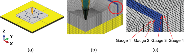
Figure 1. Schematic of a mosaic armor and gauge locations for stress analysis
The FE simulations were performed using the commercial software ABAQUS. Due to the symmetry of the problem with respect two orthogonal planes, only a quarter of the armor system was modelled. In the FE model, all the components are discretised with C3D8R elements. The whole model contains of 1340400 elements, with the smallest element located on the tip of the projectile to capture its geometry. Four layers of solid elements are used to discretise the gap-filling material in the thickness direction. The application of solid elements for the thin gap-filing material ensures the transmission of stress waves in the thickness direction to be captured. The size of the smallest ceramic element is 0.25 mm × 0.25 mm × 0.25 mm and gradually increases towards the outer edges of the structure. The backing plate represents a Kevlar-29/epoxy composite consists of 16 layers of a Kevlar-29 plain weave fabric, therefore is discretised using 16 layers of solid elements. The general contact algorithm in ABAQUS is employed for the definition of interaction between the projectile and the ceramic, as well as between the projectile and the backing plate.

2.2. Material Models

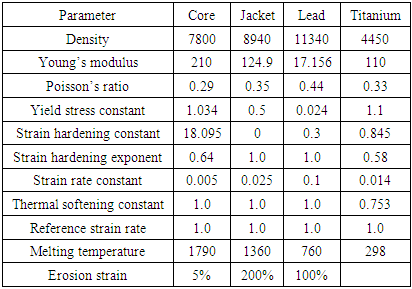
The projectile consists of three different materials as stated earlier. The Johnson Cook (JC) plasticity model [19] was selected to characterize the material behavior of all the three constituents. The JC model can predict the material response of metallic materials subjected to a high strain rate during a high velocity impact. It is commonly used in ballistic impact simulations due to its uncoupled approach in calibrating material parameters. The JC model parameters for the projectile core, jacket and lead are given in Table 1.
Table 1. JC Model Parameters of the Projectile Material [18,13]
     
The ceramic material Al2O3 is modelled using the Johnson-Holmquist (JH-2) model [21]. The JH-2 model assumes that the yield strength of the material is given by a weighted sum of the strength of the material at the intact state and fractured state. It has been implemented in ABAQUS as a built-in material model [22]. The properties assigned for Alumina (99.5%) were obtained by Anderson et al. [23] and are given in Table 2.
Table 2. JH-2 Model Parameters Used for Ceramic Material [23]
     
The backing plate of the armor structure consists of a Kevlar-29 fiber-reinforced epoxy composite. Due to the orthogonal woven structure of the fabric, it has essentially the same in-plane properties in the two perpendicular directions determined by weft and warp yarns. Experimental results show that the failure mechanism of the composites include fiber breakage, matrix cracking and interlayer delamination. In the current paper, a user defined damage model which takes into account fiber failure in the two orthogonal directions is implemented through the user subroutine VUMAT for the modelling of the composite. The formulations of the damage model are given in Ref. [24].
For the gap-filling material, two different types of materials are assigned to simulate different interface designs. The first material is an epoxy resin. Epoxy resin is a common adhesive used in armor structures for the bonding of individual components, although the exact constituents of the epoxy vary from case to case. The resin can be filled into the gap of ceramic tiles after which are appropriately assembled. This represents a typical manufacturing process as reported in Ref. [9]. In the FE model, the epoxy is modelled with an elastic-perfect plastic material model, with a density of 1.08 g/cm3, Young’s modulus of 2.7 GPa, Poisson’s ratio of 0.3, yield strength of 46.5 MPa and failure strain of 4%. The second material studied for the gap-filling material is a titanium alloy as used in Ref. [13]. Instead of filling the titanium alloy after the ceramic tiles were assembled, a titanium alloy honeycomb was fabricated through removing rectangular prisms from a monolithic titanium block. The ceramic tiles were then inserted in the honeycomb with an epoxy adhesive filled in the voids to form integral mosaic armor. This manufacturing process was also employed in the study conducted by Zhao et al. [14]. However, in their studies, only honeycomb with rectangular shaped cores were tested. while the more common hexagonal shaped cores have not been studied. It is believed that hexagonal shaped ceramic tiles are favored in the design of mosaic armor due to improved stability. In the current simulation, the hexagonal titanium honeycomb is modelled with the JC model with material properties directly obtained from Ref. [13] as are given in Table 1.
Table 3. Material Parameters of the Kevlar-29/Epoxy Composite
     
The numerical model contains several components which potentially come into contact with each other upon impact. Therefore, it is essential to define a reasonable interaction between different components. In the manufacturing process, the epoxy filler is directly adhered to the adjacent ceramic tiles in the first mosaic armor [9]. In the second mosaic armor, an epoxy was also filled into the voids after the ceramic tiles inserted into the titanium alloy honeycomb [13]. It was also observed that the ceramic tiles in both of the armor designs detached from the rest of the armor upon impact. In light of these observations, it is recognized that different components should not be tied together or have their nodes shared at the boundary as it will not reflect the real bonding condition. Instead, a cohesive surface-based interaction is defined at these interfaces, including the surface between the epoxy/honeycomb and the ceramic tiles, the surface between the ceramic tiles and the backing plate. The surface based cohesive behavior is similar to cohesive element technique [25]. It has been implemented in the software as a contact property [21]. In the current model, interface failure is assumed to be initiated when the maximum contact stress in either the normal direction or the shear direction achieves a critical value, which is 140 MPa and 68.7 MPa respectively for the two directions.

2.3. Model Validation

The validity of the current numerical model was attested by comparing simulation results of a monolithic bilayer armor with the ballistic testing. In the ballistic experiments, bilayer alumina ceramic armor backed by Kevlar-29/epoxy composite plate were impact against 7.62 mm APM2 projectiles. A picture of the specimen before and after a penetrated impact is shown in Fig. 2. The specimen tested was also covered by a thin Kevlar-29 sheet bonded onto the top surface of the ceramic tile, which is not shown here. The dimension of the ceramic tile used in the tests was 100 mm × 100 mm × 12.7 mm. The dimension of the composite backing plate was the same as that used in the current simulation. The ballistic limit of the monolithic bilayer armor from numerical simulation was 1100 m/s, very close to the experimental result of ~1090 m/s. After the monolithic bilayer model was validated, the thickness of the ceramic tile was reduced to 8 mm for the current simulation and a honeycomb shaped gap-filling structure was added as a design parameter.
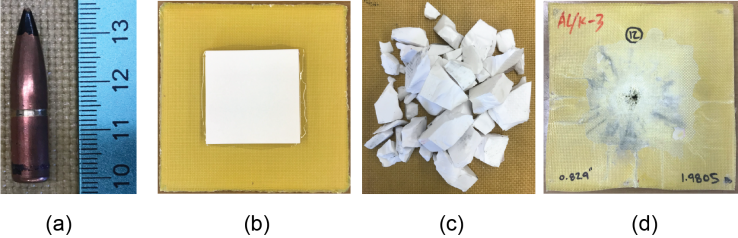
Figure 2. (a) APM2 projectile; (b) Alumina/Kevlar-29 composite armor system; (c) Alumina fragments collected after impact; (d) Kevlar-29 composite backing plate after impact

3. Results and Discussion

The ballistic resistance of the two armors with different interface designs are firstly compared. It is known that the ballistic resistance of a mosaic armor is generally less than that of a corresponding monolithic armor due to the reduced ceramic size. As a reference, the ballistic resistance of a monolithic bilayer armor, that with the same thickness but larger ceramic tile size is also presented as a reference.

3.1. Ballistic Resistance

When impacted at the canter of the ceramic tile, a relation between the impact velocity vi and the residual projectile velocity vr is plotted in Fig. 3. In each of the armor designs, the target shows a typical ballistic behavior, that the projectile would not fully perforate the target until a critical velocity is achieved. Immediately above the ballistic limit, the residual velocity of the projectile increases sharply. It can be seen that the ballistic limit of the three armor increase in the order of epoxy-filled (525 m/s), honeycomb inserted (625 m/s) and monolithic armor (675 m/s). The ballistic limit of the honeycomb inserted armor is close to that of the monolithic armor. Actually, the ballistic limit of a mosaic armor increases as the tile size increases, and eventually saturates at a critical value equivalent to that of a monolithic armor [8]. The simulation shows that for the honeycomb inserted armor, the studied tile size is very close to the critical limit. On the contrary, for the epoxy filled armor, since its ballistic limit is well below that of a monolithic armor, further increasing in the tile size will drastically improve its ballistic resistance.
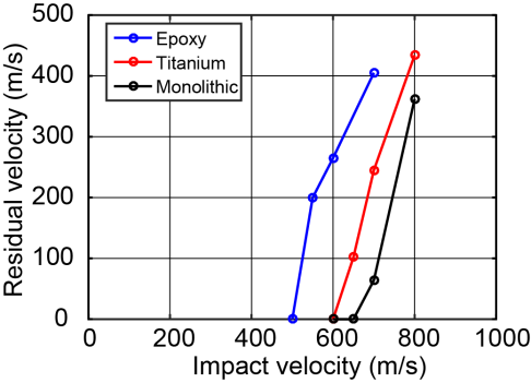
Figure 3. Residual velocity versus impact velocity relationship of the three armor
At an impact velocity close to the ballistic limit (600 m/s), the kinetic energy history of the projectiles in the two armors along with the energy dissipated by the gap filler are plotted in Fig. 4. It is noted that at this impact velocity, only the epoxy-filled mosaic armor was penetrated. The projectile kinetic energy history is an indication that the projectile is being slowed down as it penetrates through the target. In a monolithic armor, the kinetic energy of the projectile was dissipated through interaction with the ceramic front layer and the composite backing plate, while in mosaic armor, part of the projectile kinetic energy was also dissipated through the gap-filling material. The residual projectile kinetic energy of the epoxy-filled armor was much higher than that of the honeycomb-inserted armor. The projectile kinetic energy in the non-penetrated case was not reduced to zero even after the projectile has come to complete stop. This is because some projectile fragments were still moving due the impact. Moreover, it can be seen that the energy absorbed by the titanium honeycomb was much higher than that absorbed by the epoxy filler. Nevertheless, the magnitudes were relatively small in both cases, and the difference between which were much smaller than the difference between the projectile kinetic energy. The higher difference in the residual projectile kinetic energy is attributed to the energy absorbed by the ceramic tile and the backing plate. It implies that the honeycomb at least serves two important roles in mosaic armor. Firstly, it can dissipate part of the projectile kinetic energy by itself. Secondly, it helps alter the amount of kinetic energy dissipated by other components in the armor, including the ceramic tile and the backing plates. The energy absorbed by the ceramic tile and the backing plate in the armor are compared in Fig. 4b. It clearly shows a difference in the energy absorbing capacity of different components due to different gap filling material. The difference contributes to the difference in the projectile energy displayed in Fig. 4a. A stress analysis is carried out in next section to further analyse this point.
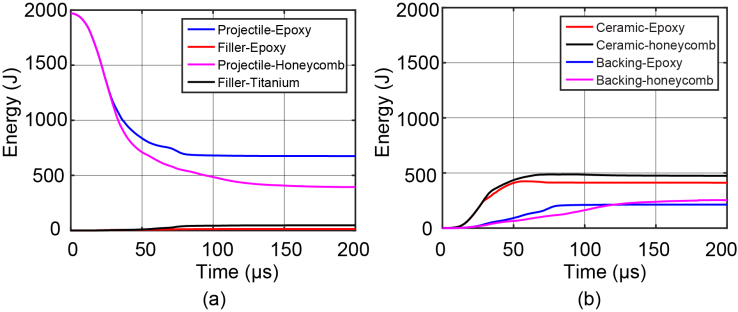
Figure 4. (a) Projectile kinetic energy history and energy dissipated by the gap-filler in the two armor. (b) Energy absorbed by the ceramic tile and the backing plate in the two armor

3.2. Stress Analysis

This section presents a stress analysis of the two types of mosaic armor when impacted at the center of the ceramic tile at 600 m/s. It is seen that the gap-filler alters the energy dissipated by each individual component. Therefor a wave tracking is performed to investigate the role of the gap-filler.
When the armor is impacted by the projectile, a dilatational wave is initiated at the impact site and propagates outward. For an unbounded medium the wave velocity C can be calculated as
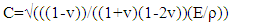
(1)
where v is the Poisson’s ratio, ρ is the density and E is the elastic modulus of the medium. The wave velocity of the alumina can thus be calculated as 10.7 km/s based on the material parameters given in Table 2. For the studied armor size, it takes roughly 5 µs for the dilatational wave to arrive at the edge of the front layer.
For the epoxy-filled armor, the time history of stress σy at the four gauges designated in Fig. 1c are plotted in Fig. 5. The four gauges are along the y-axis of three different components. Based on the appointed coordinate system, it is believed that σy dominates the wave propagation in the three locations in the first few microseconds. Fig. 5 shows that a compressive stress wave arrives at gauge one at 2.5 µs, consistent with that calculated by Eq. (1). It should be noted that there is an initial gap of 0.1 mm between the projectile and the target, which takes the projectile 0.17 µs to arrive at the target. After the stress arrived at the interface, it immediately changes to a tensile wave due to wave reflection at the interface.
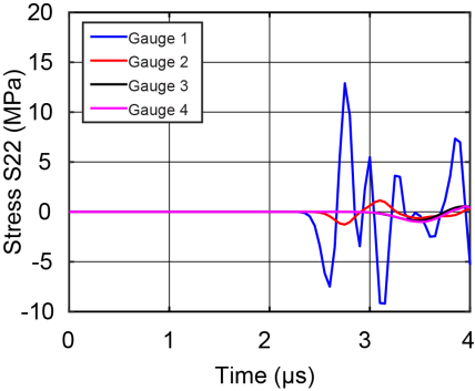
Figure 5. Stress history at the four gauges in epoxy-filled mosaic armor
Based on a one-dimensional stress wave propagation analysis in continuum, the reflected and transmitted components of a stress wave at the interface between two different mediums can be calculated as [26]:
(2)
(3)
where σI, σR and σT represent intensities of the incident, reflected and transmitted stress wave, respectively. Subscripts A and B refers to the upstream and downstream medium, respectively.
It can be calculated from Eq. (2-3) that, at the alumina-epoxy interface, σR = -0.906σI and σT = 0.094σI, while at the epoxy-alumina interface, σR = 0.906σI and σT = 1.906σI. The minus sign indicates the stress reverses its direction as it is reflected, this is consistent with the simulated stress at gauge one. If we look at the stress wave at gauge two shown in Fig. 5, it can be seen that the initially transmitted wave is in compressive direction, however the amplitude is much smaller than that of the incident wave, due to impedance mismatch. After initial reflection and transmission, the stress waves at all the gauges show a typical oscillating feature due to the subsequently arrived waves as the projectile penetrating into the target, which could not be tracked in detail.
Since Fig. 5 shows that the stress wave does not arrive at gauge one until 2.5 µs, distribution of the stress σy along the y-axis is studied around this moment. A typical σy distribution along the y-axis is given in Fig. 6a (1.0 µs). Upon impact, a very high compressive stress is developed right beneath the projectile tip and propagates outward. However, the stress amplitude of the wave front is much smaller than that under the projectile tip. Fig. 6b shows the σy distribution at 1.5 µs, 2.0 µs, 2.5 µs and 3.5 µs. To clearly display the wave front, the scale of y-axis has been adjusted. It shows that the stress wave is attenuated as it propagates outward. Boundaries of each tile and the gap-filler are designated. The interface effect is clearly observed. At 3.5 µs, the stress wave has reached tile 2, however, the stress amplitude is so small to be detected.
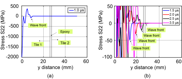
Figure 6. Stress distribution along y-axis around 2.5 µs
For the honeycomb-inserted armor, to show a comparison with the epoxy-filled armor, the stress history at the four gauges on the two amors are plotted together, respectively, as shown in Fig. 7. The two stress waves arrived at location one at the same time, however, the stress amplitude at the wave front is almost two times higher in the honeycomb-inserted armor than the epoxy-filled armor. It indicates a lower stress attenuation in the honeycomb-inserted armor, yet the reason is not clear. At gauge two (Fig. 7b), the stress wave in the honeycomb-inserted armor arrives earlier than in the epoxy-filled armor. This is due to the higher wave velocity of the titanium alloy. A remarkable difference is that the stress amplitude in the titanium honeycomb is much higher than in the epoxy. When the incident stress amplitude is the same, Eq. 3 indicates that the stress transmitted to titanium should be nine times higher than to epoxy. According to Eq. (2) and Eq. (3), at the alumina-titanium interface, σR = -0.2σI and σT = 0.8σI, while at the titanium-alumina interface, σR = 0.2σI and σT = 1.2σI. This is consistent with the simulation results. The stress comparison at gauge three shows a same feature as in gauge two. The thickness of the gap is so small that no stress attenuation is noticeable. At gauge four, stress is attained due to the transmission of which across the gap-filler. It involves a transmission of stress from a low impedance material to a higher impedance material. Eq. (3) indicates that the stress attained from epoxy would be slightly higher than from titanium (1.9/1.2) if the incident stress amplitude is the same. However, since the incident stress in the titanium is much higher than in the epoxy, the stress attained at gauge four is higher in the titanium honeycomb-inserted armor than in the epoxy-filled armor.
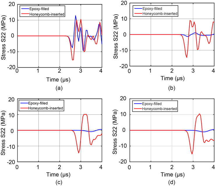
Figure 7. Stress history at (a) gauge one; (b) gauge two; (c) gauge three; (d) gauge four
The stress analysis in the first few microseconds has significant implications. Because of the impedance difference aroused due to different interface designs, the stress wave transmitted to the gap-filler and the adjacent tile is higher in the titanium honeycomb-inserted armor. Therefore, more kinetic energy is absorbed by adjacent tiles in the honeycomb-inserted armor than in the epoxy-filled armor. This is an important factor that contributes to the higher ballistic resistance of the honeycomb-inserted armor.
After the initial few seconds, further tracking of stress wave is inaccessible due to the complex wave superposition. The deformation of the two armor at some representative time instants (10 µs, 20 µs, 50 µs, 80 µs, 100 µs) are plotted in Fig. 8. The contour variable represents the damage level of ceramic material defined by the JH2 model, therefore is not available for other materials which are plotted in a uniform colour. The red colour means the ceramic material is fully damaged. A detailed explanation on the damage variable can also be found in our previous study [17]. Fig. 8 shows that due to the difference of the interface design, the damage extents in the ceramic tile of the two armors are different. Since the damage variable is governed by the stress state, it implies that different stress states in the ceramic tile have been generated due to different interface materials. If we look at the gap-filling material, we can see from Fig. 8b that some epoxy failed at 20 µs in the epoxy-filled armor, and the two adjacent ceramic tiles directly contacted with each other at their edges. On the contrary, the titanium alloy did not fail because of its high ductility. At 80 µs, a clear fracture on the rear surface of the backing plate in the epoxy-filled armor is observed. This phenomenon was also observed in our experimental tests [24] and is ascribed to the bulge of the backing plate. At the same time instant, backing plate failure was not observed in the titanium honeycomb-inserted armor, due to the relatively low kinetic energy after being eroded by the ceramic tile. It can be concluded that although the interface material was not directly involved in the contact with the projectile, it exerts a significant influence on the performance of the armor by affecting the damage extent. At 100 µs, the deformed gap-filling material in the two armor are shown in Fig. 9. Some of the epoxy elements are automatically deleted after failure, while most of honeycomb elements are retained. The failure of the epoxy lead to more and more direct contact between adjacent ceramic tiles, which could be avoided in the honeycomb-inserted armor.
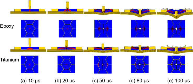
Figure 8. Deformation of the two types of armor at different time instants
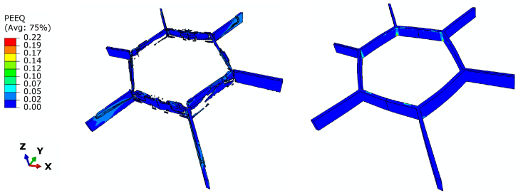
Figure 9. Deformation of epoxy filler and titanium honeycomb in the two armor at 100 µs

4. Conclusions

In this paper, we developed a 3D finite element model for mosaic armor and investigated ballistic performance of two mosaic armor systems with different interface designs. It was found that when the armor is impacted at the center of a ceramic tile, the ballistic performance is strikingly different for different gap-filling material. Although the tile-to-tile interface was not directly involved in contact with the projectile, the ballistic limit of the titanium honeycomb-inserted armor shows 19% higher than the epoxy filled armor. While the interface material itself only absorbs a very small portion of the kinetic energy from the projectile, it exerts influence on the ballistic behavior of the armor through changing the energy absorption capability of other components, including the ceramic tile and the backing plate. A stress wave analysis indicates that the stress transmitted to adjacent tiles through the titanium honeycomb is higher than through the epoxy. The stress wave transmission enables more kinetic energy to be absorbed by adjacent tiles. These results have practical values for the design of mosaic armor, i.e., the interface material can be considered as a design parameter to be tailored, with the objective of increasing single hit impact resistance through transmitting stress wave to adjacent tiles while keeping it within a limit so as not to induce fracture thus compromise its multi-hit resistance.

ACKNOWLEDGEMENTS

This work was supported by the Army Research Office (ARO) Grant Award Number W911NF-18-1-0478.

References

[1]  Wilkins ML, Cline CF, Honodel CA. Fourth progress report of light armor program. Livermore: Lawrence Livermore Laboratory; 1969.
[2]  Übeyli M, Deniz H, Demir T, Ögel B, Gürel B, Keles Ö. Ballistic impact performance of an armor material consisting of alumina and dual phase steel layers. Mater Des 2011; 32(3): 1565–70.
[3]  Chi R, Serjouei A, Sridhar I, Tan GE. Ballistic impact on bi-layer Alumina/aluminium armor: a semi-analytical approach. Int J Impact Eng 2013; 52: 37–46.
[4]  Lee M, Yoo YH. Analysis of ceramic/metal armour systems. Int J Impact Eng 2001; 25(9): 819-829.
[5]  Gregori D, Scazzosi R, Nunes SG, Amico SC, Giglio M, Manes A. Analytical and numerical modelling of high-velocity impact on multilayer Alumina/aramid fiber composite ballistic shields: improvement in modelling approaches. Compos Part B Eng 2020; 187: 107830.
[6]  Gama BA, Bogetti TA, Fink BK, Yu CJ, Claar TD, Eifert HH, Gillespie JW. Aluminum foam integral armor: a new dimension in armor design. Compos Struct 2001; 52(3-4): 381–395.
[7]  Ong C, Boey C, Hixson RS, Sinibaldi JO. Advanced layered personnel armor. Int J Impact Eng 2011; 38(5): 369–383.
[8]  Hazell PJ, Roberson CJ, Moutinho M. The design of mosaic armour: the influence of tile-size on the ballistic performance. Mater Des 2008; 29(8): 1497–503.
[9]  Jiusti J, Kammer EH, Neckel L, Loh NJ, Trindade W, et al. Ballistic performance of Al2O3 mosaic armor with gap-filling materials. Ceram Int 2017; 43: 2697–704.
[10]  Hu D, Zhang Y, Shen Z, Cai QY. Investigation on the ballistic behavior of mosaic SiC/UHMWPE composite armor systems. Ceram Int 2017; 43(13): 10368–76.
[11]  Seifert W, Strassburger E, Dolak M, et al. Experimental study on the dependency of the ballistic performance of tiled ceramic/metal targets on inter tile gap width and projectile impact position. Int J Impact Eng 2018; 122(12): 50–9.
[12]  Wadley HNG, O'Masta MR, Dharmasena KP, Compton BG, Gamble EA, Zok FW. Effect of core topology on projectile penetration in hybrid aluminum/alumina sandwich structures. Int J Impact Eng 2013; 62: 99–113.
[13]  An X, Yang J, Tian C, Wang B, Guo H, Dong Y. Penetration resistance of hybrid metallic honeycomb structures with ceramic insertions against long-rod tungsten projectiles. Composite Struct 2018; 189: 488–97.
[14]  Zhao Z, Han B, Li F, Zhang R, Su P, et al. Enhanced bi-layer mosaic armor: experiments and simulation. Ceram Int 2020; 46: 23854–66.
[15]  Krishnan K, Sockalingam S, Bansal S, Rajan SD. Numerical simulation of ceramic composite armor subjected to ballistic impact. Compos Part B Eng 2010; 41(8): 583–593.
[16]  Bürger D. Rocha de Faria A, de Almeida SFM, de Melo FCL, Donadon MV. Ballistic impact simulation of an armour-piercing projectile on hybrid ceramic/fiber reinforced composite armours. Int J Impact Eng 2012; 43: 63–77.
[17]  Guo G, Alam S, Peel LD. Numerical analysis of ballistic impact performance of two ceramic-based armor structures. Compos Part C Open Access 2020; 3: 100061.
[18]  Anderson Jr CE, Burkins MS, Walker JD, Gooch WA. Time-resolved penetration of B4C tiles by the APM2 bullet. Computer Modeling in Engineering & Sciences 2005; 8(2): 91–104.
[19]  Johnson GR, Cook WH. Fracture characteristics of three metals subjected to various strains, strain rates, temperatures and pressures. Eng Fract Mech 1985; 21(1): 31–48.
[20]  Fras T, Murzyn A, Pawlowski P. Defeat mechanisms provided by slotted add-on bainitic plates against small-calibre 7.62 mm x 51 AP projectiles. Int J Impact Eng 2017; 103: 241–53.
[21]  Johnson GR, Holmquist TJ. An improved computational constitutive model for brittle materials. AIP conference proceedings. AIP Publishing; 1994, pp. 981–984.
[22]  ABAQUS Documentation, Version 2017, Dassault Systemes Simulia Corp. 2017.
[23]  Anderson CE Jr, Johnson GR, Holmquist TJ. Ballistic experiments and computations of confined 99.5% Al2O3 ceramic tiles. In: 15th International Symposium on Ballistics, Jerusalem, Israel; 1995, pp. 65–72.
[24]  Tan LB, et al. Performance of an advanced combat helmet with different interior cushioning systems in ballistic impact: experiments and finite element simulations. Int J Impact Eng 2012; 50: 99–112.
[25]  Guo G, Zhu Y. Cohesive-shear-lag modeling of interfacial stress transfer between a monolayer graphene and a polymer substrate. J. Appl. Mech 2015; 82(3): 031005.
[26]  Goel R, Kulkarni MD, Pandya KS, et al. Stress wave micro–macro attenuation in ceramic plates made of tiles during ballistic impact. Int J Mech Sci 2014; 83(4): 30–7.