G. Apsar , Md Musthak , Jaleel Ahmed
Department of Mechanical Engineering, Deccan College of Engineering & Technology, Hyderabad, Telangana State, India
Correspondence to: Md Musthak , Department of Mechanical Engineering, Deccan College of Engineering & Technology, Hyderabad, Telangana State, India.
| Email: |  |
Copyright © 2020 The Author(s). Published by Scientific & Academic Publishing.
This work is licensed under the Creative Commons Attribution International License (CC BY).
http://creativecommons.org/licenses/by/4.0/

Abstract
This experiment deals with the design and manufacturing of E glass/Epoxy based composite helical spring. The fuel efficiency and emission gas regulation of automobiles are two important issues in these days. The best way to increase the fuel efficiency is to reduce the weight of the automobile by employing composite materials in the structure of the automobiles. Springs are crucial suspension elements on automobiles which are necessary to minimize the vertical vibration, impacts and bumps due to road irregularities and create a comfortable ride. Coil springs are commonly used for automobiles suspension and industrial applications. Metal coils springs can be replaced by composite springs because of weight reduction and corrosion resistance. Composite coil springs can be manufactured using carbon/graphite/glass fibers and resin impregnation. Composite coil springs, compared to standard metal coil springs reduces weight from 45% to 25%, gives high natural frequency, Excellent NVH property, and corrosion free behavior. Some researchers have used the E-glass fibers and carbon fibers and low-cost resin for fabricating the coil spring. The deflections and axial stresses are the design constraints for the selection of fiber orientations in glass fiber epoxy-based composites. Taguchi’s experimental design procedure may be adopted as a vehicle for conducting the simulation experiments more efficiently and effectively. In present paper three parameters (Internal diameter of the spring, Thickness of the spring, Number of coils of the spring) and two levels (high and low) are considered. The experimental design proposed by Taguchi involves using L4 orthogonal array to organize the parameters affecting the process and the levels at which they should be varies. A composite helical spring is developed using Tape winding technology as per the proposed L4 orthogonal array. And experimental compression test was carried out for Maximum load bearing capacity of E glass epoxy-based spring. By observing the Taguchi results number of turns was analysed 1st rank, Diameter of spring was analysed 2nd rank and Thickness of spring was analysed 3rd rank. From the statistical analysis, it appears that large majority 63% maximum load bearing for Diameter of spring, Thickness of spring and Number of turns of spring fall within the range and only 37% exceeds the recommended range.
Keywords:
Composite materials, Helical springs, Maximum load bearing, Composite Helical Springs, E-Glass/Epoxy
Cite this paper: G. Apsar , Md Musthak , Jaleel Ahmed , Study of Factors Affecting Tape-Wound Composite Helical Spring Prepared by E-Glass/Epoxy by Using Taguchi Method and Statistical Distributions, International Journal of Composite Materials, Vol. 10 No. 1, 2020, pp. 10-17. doi: 10.5923/j.cmaterials.20201001.02.
1. Introduction
Composite materials can be defined as materials that consist of two or more chemically and physically different phases separated by a distinct interface to create a superior or unique material, or composite describes as reinforced plastics [1]. The best way to increase the fuel efficiency is to reduce the weight of the automobile by employing composite materials in the structure of the automobiles. Metal coil springs can be replaced by composite springs because of high strain energy, less weight and high corrosion resistance.Composite coil springs have many advantages over the conventional ones: they are light and have better performance in fatigue and dynamic response. In addition to the structural benefits, composite springs can be designed to render the optimal mechanical properties by tailoring the orientations and content of reinforcing fibers [6,8-11,15]. They have been typically manufactured by the filament winding (F/W) process. Although this process can be cost-effective, the reinforcing fibers may be limited in the longitudinal direction for small composite springs, which results in low strength and stiffness in the transverse direction [2]. Also, due to the limitation of reinforcing direction, optimized structure is hardly to be achieved in the hand Filament Winding process. Recent improvement comprises, recombining resin and reinforcement to form SMC, a moldable composite in sheet form. This eliminates the need of handling liquid resin at the press [4-5].A coil spring, also known as a helical spring, is a mechanical device, which is typically used to store energy due to resilience and subsequently release it, to absorb shock, or to maintain a force between contacting surfaces. They are made of an elastic material formed into the shape of a helix which returns to its natural length when unloaded [3].One type of coil spring is a torsion spring: the material of the spring acts in torsion when the spring is compressed or extended. The quality of spring is judged from the energy it can absorb. The spring which is capable of absorbing the greatest amount of energy for the given stress is the best one. Metal coil springs are made by winding a wire around a shaped former - a cylinder is used to form cylindrical coil springs.Design of Helical Spring.Energy storage is greater for rectangular wire compression springs, also called die springs, however round wire rates can be increased if springs are nested inside one another. Rectangular wire is used to reduce solid height or increase the space efficiency of the design [7]. Most die springs are made from rectangular wire for this reason.In applications where space is limited and particularly where solid height is restricted, springs designed from rectangular wire are often used. These springs are commonly referred to as die springs. Die springs store more energy in a smaller space than equivalent round-wire springs. Even though stress distribution around the rectangular cross section is not as uniform as the round wire section, the energy storage capacity is higher because more material can be incorporated into the allocated space [12-14].Consider a helical compression spring made of rectangular wire and subjected to an axial load W as shown in figure 1.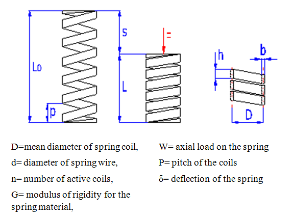 | Figure 1. Helical spring |
Taguchi methodTaguchi’s experimental design procedure may be adopted as a vehicle for conducting the simulation experiments more efficiently and effectively. The intention of this paper is to study the effect of some key design and control parameters on the performance, within which, information delay in the form of review period and decision delays are present. Our motivation here is in outlining a methodology which would help system designers/controllers get a quick insight into the relative importance of various design and control factors with respect to a defined measure of performance.The Taguchi experimental design paradigm is based on the matrix experiments technique [Phadke, 1989]. Experimental matrices are essentially special orthogonal arrays (OA) which allow that simultaneous effect of several process parameters are studied efficiently. The Taguchi method involves reducing the variation in a process through robust design of experiments. The overall objective of the method is to produce high quality product at low cost to the manufacturer. The Taguchi method was developed by Dr. Genichi Taguchi of Japan who maintained that variation. Taguchi developed a method for designing experiments to investigate how different parameters affect the mean and variance of a process performance characteristic that defines how well the process is functioning. The experimental design proposed by Taguchi involves using orthogonal arrays to organize the parameters affecting the process and the levels at which they should be varies. Instead of having to test all possible combinations like the factorial design, the Taguchi method tests pairs of combinations. This allows for the collection of the necessary data to determine which factors most affect product quality with a minimum amount of experimentation, thus saving time and resources. The Taguchi method is best used when there are an intermediate number of variables (3 to 50), few interactions between variables, and when only a few variables contribute significantly. To determine the effect of each variable from the output, the signal-to-noise ratio, or the SN number, needs to be calculated for each experiment conducted. The calculation of the SN for the first experiment in the array is shown below for the case of a specific target value of the performance characteristic. In the equations below,  is the mean value and
  is the variance.
  is the value of the performance characteristic of a given experiment. For the case of maximizing the performance characteristic, the following definition of the SN ratio should be calculated:
2. Methodology and Materials
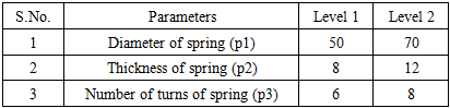
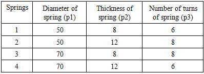
Parameters used: While there are many standard orthogonal arrays available, each of the arrays is meant for a specific number of independent design variables and levels. In present paper three parameters (Internal diameter of the spring, Thickness of the spring, Number of coils of the spring) and two levels (high and low) as shown in table 1. The L4 orthogonal array is meant or understanding the effect of 3 independent factors each having 2 factor level values. This array assumes that there is no interaction between any two factors. The table 2 shows the L4 orthogonal array. Table 1. Parameters with levels
 |
| |
|
Table 2. L4 orthogonal Array of Parameters arrangement for the mandrels to manufacture the springs
 |
| |
|
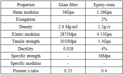
In put parameters with levels: Once the experimental design has been determined and the trials have been carried out, the measured performance characteristic from each trial can be used to analyze the relative effect of the different parameters. To demonstrate the data analysis procedure, the following L4 array will be used, but the principles can be transferred to any type of array. Terms used in compression springs: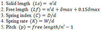 Properties of matrix and reinforcement materials: The E-glass was considered as fiber material for its cheaper cost and lower weight compared with steel and aluminum. Epoxy (LAPOX L-12) is considered as matrix and suitable hardener of (K-6) was used for curing of resin at room temperature. The properties of Glass fiber and resin are tabulated in table 3.
Table 3. Properties of glass fiber and resin
 |
| |
|
Fabrication of mandrel:A mild steel Mandrel 1 is manufactured with diameter 50mm, length 240mm with threading of depth 8mm as one set for spring 1 as mentioned in the table 2. Similarly, Mandrel 2, Mandrel 3 and Mandrel 4 are manufactured by using Milling machine as shown in figure 2.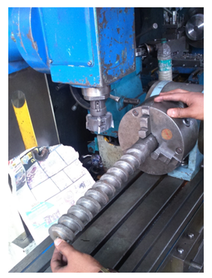 | Figure 2. Mandrel on milling head stock |
Fabrication of spring using E-glass/epoxy:The woven fabric tapes were prepared according to dimensions required. Resin was prepared by mixing the Epoxy (LAPOX L-12) and k-12 hardener. This epoxy resin was then applied on the on the fiberglass tapes wounded on Mandrel, which is fixed on the lathe head stock and was left for proper curing. Hence, the four different combinations were prepared. After curing the springs were removed from the mandrel. Hence the E glass /epoxy based 4 helical springs with 3 samples each were prepared as per the details tabulated in table 2. One sample of each spring is shown in figure 3.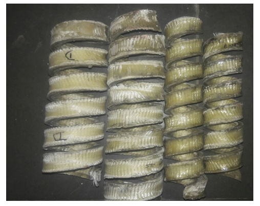 | Figure 3. E-Glass/Epoxy Helical springs manufactured according to L4 Orthogonal array |
Experimental work.In the study of strength of materials, the compressive strength is the capacity of a material or structure to withstand loads tending to reduce size. It can be measured by plotting applied force against deformation in a testing machine. Some materials fracture at their compressive strength limit; others deform irreversibly, so a given amount of deformation may be considered as the limit for compressive load. Compressive strength is a key value for design of structures. Compression testing was performed on all the springs by using universal testing machine. As shown in figure 4.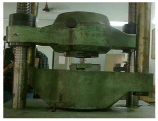 | Figure 4. E-Glass/Epoxy Helical springs on universal testing machine for compression test |
3. Results and Discussions
Spring 1 consist of diameter 50mm, depth 8mm and no of coils 6 is manufactured by using E-glass/epoxy,is tested on spring testing machine and its maximum bearing loads for 3 samples were tabulated in table 4 and average deflection of 3 samples were shown in figure 5.Spring 2 consist of diameter 50mm, depth 12mm and no of coils 8 is manufactured by using E-glass/epoxy, is tested on spring testing machine and its maximum bearing loads for 3 samples were tabulated in table 4 and average deflection of 3 samples were shown in figure 5.Spring 3 consist of diameter 70mm, depth 8mm and no of coils 8 is manufactured by using E-glass/epoxy ,is tested on spring testing machine and its maximum bearing loads for 3 samples were tabulated in table 4 and average deflection of 3 samples were shown in figure 5.Spring 4 consist of diameter 70mm, depth 12mm and no of coils 6 is manufactured by using E-glass/epoxy ,is tested on spring testing machine and its maximum bearing loads for 3 samples were tabulated in table 4 and average deflection of 3 samples were shown in figure 5.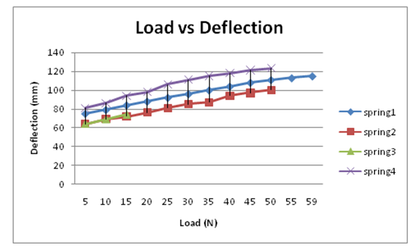 | Figure 5. Load Vs Deflection Graph for composite springs |
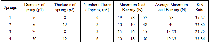
Table 4 shows the L4 Array results for compression test on E-Glass/epoxy helical springs manufactured. The maximum load bearing capacity of the 4 springs with 3 samples each were measured by using UTM and Average maximum load Bearing and its S/N ratios were calculated and tabulated in table 4.Table 4. L4 Array Results for Compression test on E-Glass/epoxy helical springs
 |
| |
|
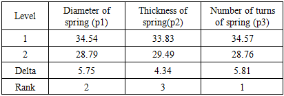
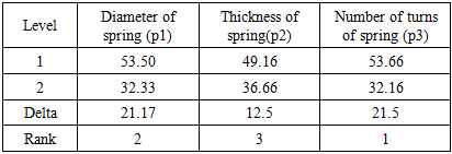
From the Figure 6 & Figure 7,“A” indicates p1 (diameter of spring), “B” indicates p2(thichness of spring) and “C” indicates p3(number turns of helical spring). By observing the graphs it is noticed that when the diameter of spring is small, the maximum load bearing is more and the maximum load bearing decreases as diameter increases. From the line p2 (thichness of spring) it is noticed that maximum load bearing is more when thickness of spring is big and maximum load bearing will decrease with the decrease in thickness. And From the line p3 (number turns of helical spring) it is noticed that when the number turns of helical spring is less, the maximum load bearing is more and the maximum load bearing decreases as number turns of helical spring increases. Table 5 shows the Response Table for Signal to Noise Ratios for Larger is better and table 6 shows the Response Table for Means. By observing both the tables 5 & 6 number of turns was analysed 1st rank, Diameter of spring was analysed 2nd rank and Thickness of spring was analysed 3rd rank.Table 5. Response Table for Signal to Noise Ratios for Larger is better
 |
| |
|
Table 6. Response Table for Means
 |
| |
|
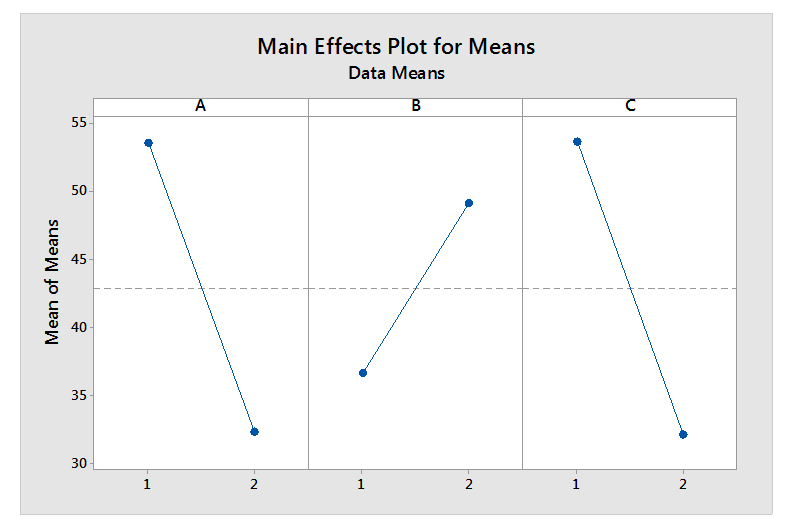 | Figure 6. Main Effects plot for means of parameters (A-diameter of spring, B-thichness of spring and C-number of turns of helical spring) |
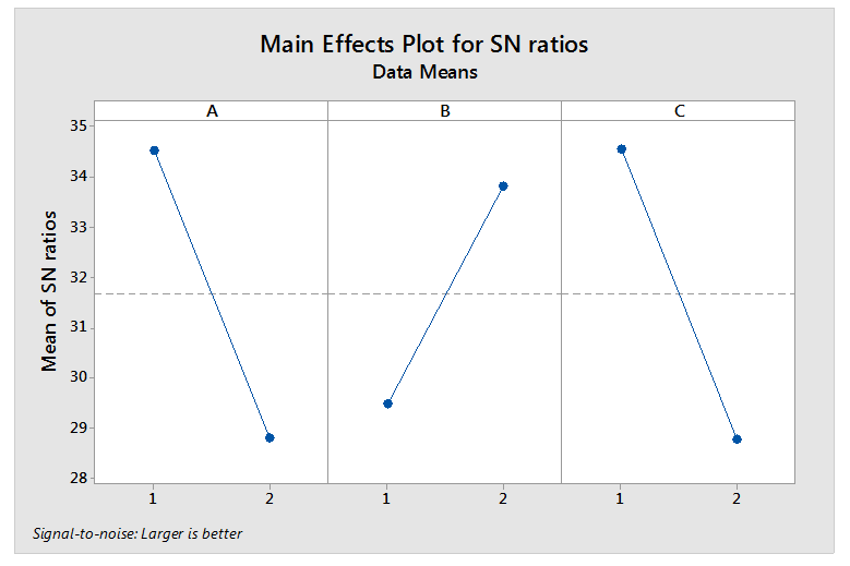 | Figure 7. Main Effects plot for S/N ratio of parameters (A-diameter of spring, B-thichness of spring and C-number of turns of helical spring) |
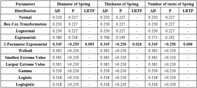
Statistical Analysis: By the help of Minitab17 handy tool allows to easily compare how well the considered data is fit for 16 different distributions as shown in table 7. Before observing through the output, there are 3 measures need to know.Anderson-Darling statistic (AD): Lower AD values indicate a better fit. However, to compare how well different distributions fit the data, it should assess the p-value, as described below.P-value: It’s generally valid to compare p-values between distributions and go with the highest. A low p-value (e.g., < 0.05) indicates that the data don’t follow that distribution. LRT P: For 3-parameter distributions only, a low value indicates that adding the third parameter is a significant improvement over the 2-Parameter version. A higher value suggests that it may want to stick with the 2-Parameter version.By observing the Table 7 (Goodness of fit test), the first row shows present data was not normally distributed, because the p-value for Normal is less than 0.005. Hence the two transformations (Box-Cox and Johnson) to be skip to identify the native distribution rather than transform it. A good place to start is to skim through the p-values and look for the highest. The highest p-value is for 2-Parameter Exponential. For the 2-Parameter Exponential, the LRT P is 0.093, which means that the 2-Parameter Exponential significantly improves the fit. Table 7. Goodness of Fit Test
 |
| |
|
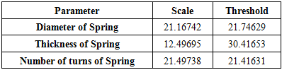
Given the higher p-value and LRT P value, we can pick the 2-Parameter Exponential distribution as the best fit for present data. So far, from the data the distribution and the parameter values for the Diameter of the spring, Thickness of spring and Number of turns of spring for 2-Parameter Exponential distribution were noted in table 8.Table 8. Estimates of 2-Parameter Exponential distributionParameters
 |
| |
|
Because the 2-Parameter Exponential distribution is identified as the best-fitting distribution, let’s prepare the inferences about the maximum load bearing for Diameter of the spring, Thickness of the spring and Number of turns of spring. The graph for best estimate of maximum load bearing for Diameter of the spring, Thickness of spring and Number of turns of spring were prepared and calculation of probabilities for values that fall in certain ranges were carried out.In the graph as shown in figure 8, the data values are on the X-axis and the percentiles are on the Y-axis. For the Diameter of spring, the 50th percentile (the median) corresponds to maximum load bearing of 36.418 N. 95% of the maximum load bearing for Diameter of spring should fall between the 2.5% and 97.5%, which correspond to maximum load bearing of 22.282 N and 99.830 N. Maximum load bearing of 42.915 N for Diameter of spring corresponds to the 63%. From the graph, it appears that large majority 63% maximum load bearing for Diameter of spring fall within the range and only 37% exceeds the recommended range. 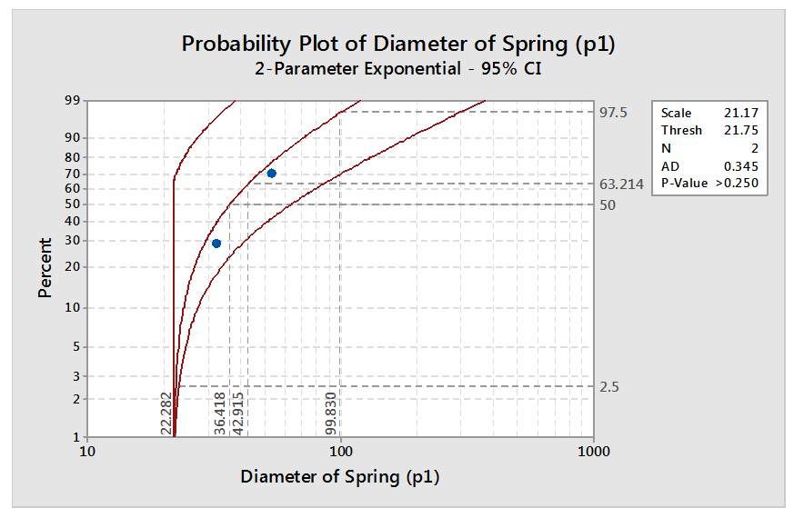 | Figure 8. Probability plot for maximum load bearing of Diameter of spring |
In the graph as shown in figure 9, the data values are on the X-axis and the percentiles are on the Y-axis. For the Diameter of spring, the 50th percentile (the median) corresponds to maximum load bearing of 39.0788 N. 95% of the maximum load bearing for Diameter of spring should fall between the 2.5% and 97.5%, which correspond to maximum load bearing of 30.7329 N and 76.5163 N. Maximum load bearing of 42.915 N for Diameter of spring corresponds to the 63rd percentile. From the graph, it appears that large majority 63% maximum load bearing for Diameter of spring fall within the range and only 37% exceeds the recommended range. 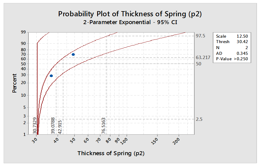 | Figure 9. Probability plot for maximum load bearing of Thickness of spring |
In the graph as shown in figure 10, the data values are on the X-axis and the percentiles are on the Y-axis. For this Diameter of spring, the 50th percentile (the median) corresponds to maximum load bearing of 36.317 N. 95% of the maximum load bearing for Diameter of spring should fall between the 2.5% and 97.5%, which correspond to maximum load bearing of 21.961N and 100.718 N. Maximum load bearing of 42.915 N for Diameter of spring corresponds to the 63rd percentile. From the graph, it appears that large majority 63% maximum load bearing for Diameter of spring fall within the range and only 37% exceeds the recommended range. 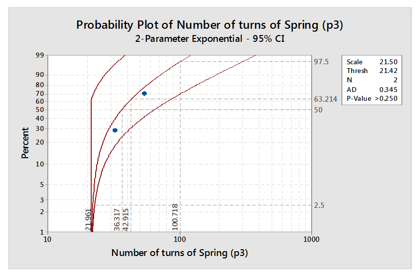 | Figure 10. Probability plot of maximum load bearing of Diameter of spring |
4. Conclusions
The design and manufacturing with E-Glass epoxy based helical spring with epoxy resin on rectangular cross section mandrel was successfully manufactured using tape winding method at room temperature and tested. The experiment on compressive tests conducted with E-Glass fiber and resin enhancements show that there will be an increase in universal compressive load when properly compressed and also sustain greater break loads. By the test results achieved we find that deflection of spring of E-glass fiber in the Epoxy resin plays a major role in deciding the strength factor the composite material will have. It tends to create that bonding between the matrix and the E-glass fiber tapes which helps to increase the maximum load bearing of composite material. The springs produce a large deflection with less weight are used for a number of applications. The thread-based spring having large deflection with less weight when compare to material-based spring. By observing the Taguchi results number of turns was analysed 1st rank, Diameter of spring was analysed 2nd rank and Thickness of spring was analysed 3rd rank. From the statistical analysis, it appears that large majority 63% maximum load bearing for Diameter of spring, Thickness of spring and Number of turns of spring fall within the range and only 37% exceeds the recommended range.
References
| [1] | Tsai SW, Hahn HT. Introduction to composite materials. Technomic Publishing; 1980. |
| [2] | Mayer, Rayner M. (1993). Design with reinforced plastics. Springer. p. 7. ISBN 978-0-85072-294-9. |
| [3] | Helical compression and extension spring terminology SAE J1121, In: SAE Handbook, SAE, 1999. |
| [4] | Robert M. Jones (1999). Mechanics of Composite Materials (2nd ed.). |
| [5] | Matthews, F.L. & Rawlings, R.D. (1999). Composite Materials: Engineering and Science. Boca Raton: CRC Press. |
| [6] | Van Tooren Antonelli, V. and Antoniazzi, A., ‘Feasibility study on the production of a composite helical spring', In: Proc. 21th SAMPE International Conference, (2000). |
| [7] | Gobbi, M, Mastinue, G., “On the optimal design of composite tubular helical springs”, Physics and Astronomy, Meccanica, Vol 36, pp. 525-533, 2001. |
| [8] | Pervin Farhana, Zhou Yuanxin, Mohammad A. Biswas, Rangari Vijaya K., Jeelani Shaik: Fabrication and Characterization of Clay/epoxy nanocomposite, Materials Letters, 60, (2006). |
| [9] | Waterman, Pamela J. "The Life of Composite Materials". Desktop Engineering Magazine. April 2007. |
| [10] | Wallenberger, F. T., Hicks, R. J., Simcic, P. N., Bierhals, A. T. (2007) New environmentally and energy friendly fiberglass compositions (E-glass, ECR-glass, C-glass and A-glass). Glass Technol. Eur. J. Glass Sci. Technol. A 48: pp. 305-315. |
| [11] | Jump up^ Türschmann, V.; Jakschik, C.; Rother, H.-J. White Paper, Topic: "Clean Air in the Manufacture of Glass Fibre Reinforced Plastic (GRP) Parts". GRP Technique & Service (March 2011). |
| [12] | Mehdi Bakhshesh and Majid Bakhshesh „Optimization of Steel Helical Spring by Composite Spring INTERNATIONAL JOURNAL OF MULTIDISCIPLINARY SCIENCES AND ENGINEERING, VOL. 3, NO. 6, JUNE 2012‟. |
| [13] | P.S.Valsange „‟ Design Of Helical Coil Compression Spring” A Review‟ International Journal of Engineering Research and Applications, Vol. 2, Issue 6, November- December 2012, pp. 513-522. |
| [14] | Musthak Md and Madhavi M, “Development of high strength helical coiled springs using carbon pre-preg epoxy based composite.” Indian Journal of Scientific Research. Vol.4, No.2, pp. 109-114, (2013). |
| [15] | Suresh. G, Vignesh. R, Aravinth. B, Padmanabhan. K, A. Thiagararajan„‟ Fabrication and Analysis of Nano Composite Cylindrical Helical Spring‟‟ International Journal of Innovative Research in Science, Engineering and Technology, Volume 3, Special Issue 1, February 2014. |

 Abstract
 Reference
 Full-Text PDF
 Full-text HTML