Md Musthak1, M. Madhavi2, P. M. Valli3
1Associate Professor, Department of Mechanical Engineering, Deccan College of Engineering & Technology, Hyderabad, Telangana State, India
2Professor, Department of Mechanical Engineering, M. V. S. R. Engineering College, Hyderabad, Telangana State, India
3Director, S.V. College of Engineering, Kadapa, Andhra Pradesh, India
Correspondence to: Md Musthak, Associate Professor, Department of Mechanical Engineering, Deccan College of Engineering & Technology, Hyderabad, Telangana State, India.
| Email: |  |
Copyright © 2019 The Author(s). Published by Scientific & Academic Publishing.
This work is licensed under the Creative Commons Attribution International License (CC BY).
http://creativecommons.org/licenses/by/4.0/

Abstract
Advanced Fiber reinforced polymers have emerged as an important class of engineering materials with all round properties for many engineering and social applications. Fiber reinforced composites are widely used in aircrafts, rockets and automotive structures for their low weight high strength and stiffness. A designer can utilize the anisotropy produced by building up a laminate from plies with a properly selected fiber-resin combination and orientation-stacking sequence to meet the performance requirements. The axi-symmetric structure like a pressure vessel would be made out of composite materials usually using filament winding process. In spite of their good performance; pressure vessels made by filament winding have complexity in analyzing the geometry and properties in their dome parts along the longitudinal axis. Moreover, the fiber angle varies in the thickness direction because the fiber path depends on the surface on which fibers are wound. Therefore certain analyses like higher order shear deformation theory and finite element analysis is to be computed in order to predict the structural behavior of pressure vessel. By observing the results among these numerical techniques, it is seen that the Finite element method is not only simple but straight forward for efficient programming and also versatile enough to cover all types of problems relevant to practical situations.
Keywords:
Composite Pressure Vessel, First order Shear Deformation Theory, Third order Shear Deformation Theory, Finite Element Analysis
Cite this paper: Md Musthak, M. Madhavi, P. M. Valli, Study of Inter-Laminar Behavior of Geodesic wound Composite Pressure Vessel by Higher Order Shear Deformation Theories and Finite Element Analysis, International Journal of Composite Materials, Vol. 9 No. 3, 2019, pp. 60-68. doi: 10.5923/j.cmaterials.20190903.02.
1. Introduction
A Filament winding is an automated process in which continuous filament is treated with resin and wound on a mandrel in a pattern designed to give strength in one direction. The composite pressure vessel fully wrapped with epoxy-impregnated E-glass fiber is considered. The quality and strength of the final component depends, to a large extent, on accurate placement of the fibers or tapes on the predefined path. It is well known that the ideal curve on the mandrel surface for placement of fibers is the Geodesic curve. Geodesic winding can be conveniently carried out on the conventional end dome shapes by the method of Claurit’s Principle  as shown in Figure 1. The overall length of the casing is determined based on the volume requirement. Netting analysis is used to formulate and solve the nonlinear equations that result from this interaction between the dome shape and fiber orientation angles [5,6, and 10].
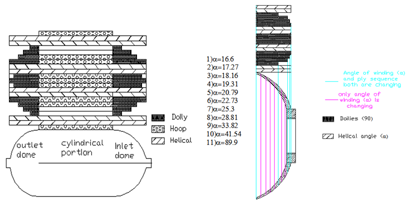 | Figure 1. Winding angle along the meridian and ply sequence on the composite pressure vessel |
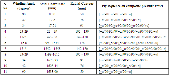
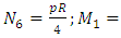
Netting Analysis is used in predicting stresses in a fiber reinforced composite by neglecting the contribution of the resin system. The cylinder of the filament wound pressure vessel was basically composed of helical and hoop layers. Whereas the end domes comprises of helical and doilies. Doily is a planar reinforcement applied to local areas to provide additional strength, usually in hoop direction. Since it is not possible to wind hoop layers on the end domes directly by filament winding technique, an additional layer either a unidirectional fabric or drum wound hoop layers are developed and placed on the end domes. The preliminary design is performed using netting analysis methods to address the inner pressure loading. Netting analysis assumes that the fibers provide all of the stiffness and strength in the cylinder. This assumption is not only conservative but also an excellent basis for quick calculation of composite thickness. From netting analysis, Consider a filament wound cylinder of radius R pressurized with an internal pressure P. Hoop layers are not possible to develop on the dome portions so that doilies are provided for the balance requirement. The helical layers are not effective for axial stresses towards the pole openings, where the doilies can bare radial and axial stresses. The required hoop thickness, helical thickness and doily thickness are designed by equations (1), (2) & (3) respectively. The designed ply sequence is shown in Table 1. Table 1. Details of the Ply Sequence on the Composite Pressure Vessel
 |
| |
|
 | (1) |
 | (2) |
 | (3) |
Literature SurveyT. Kant et al [8] present a refined higher-order theory for free vibration analysis of un-symmetrically laminated multilayered plates. The theory accounts for parabolic distribution of the transverse shear strains through the thickness of the plate and rotary inertia effects. Ngo Nhu Khoa et al [14] presents a rectangular non–conforming element based on Reddy’s higher-order shear deformation plate theory is developed. F. Auricchio et al [1] proposed mixed variational formulations for a first-order shear deformation laminate theory. M. Rastgaar Aagaah et al [15] presented natural frequencies of square laminated composite plates for different supports at edges. S Latheswary et al [10] studied the behavior of laminated composite plates under static loading by using a four-noded element with seven degrees of- freedom per node, based on higher-order shear deformation theory.T. Kant et al [9] presents a higher-order displacement model for the behavior of symmetric and un-symmetric laminated composite and sandwich cylindrical shells based on C° finite element discretization. X. Huang et al [6] presents a simple and efficient method is used for buckling analysis of a laminated circular cylindrical shell based on a two-surface theory. Csonka. B. et al [5] presented structural and sensitivity analysis for the optimization of laminated axisymmetric shells subjected to static constraints and arbitrary loading.Cho-chung Liang et al [4] have performed studies on an optimum end dome contours for filament- wound composite pressure vessels, subjected to geometrical limitations, winding condition, which can very closely perform the isotensoid behavior. Jae-Sung Park et al [7] have studied structural analysis of composite pressure vessel by considering the geodesic path deviation (non-geodesic trajectory) on an end dome of an arbitrary surface. Semi geodesic path equations are developed for the contour and further carried out FEA using Abacus software. In the above cases the prediction of failure of the arbitrary contour structure becomes difficult. Moreover for known curvatures, like cylinder, hemispherical and iso tensoid contours, it is easy to quantify the design parameters such as winding thickness and winding angle. Cheol-Ung Kim et al [3] developed semi geodesic path algorithm to calculate possible winding patterns and also performed Finite element analysis. Beakou. A and Mohamed. A [2] used the Classical laminated theory in order to analyse the influence of variable scattering on the optimum winding angle of cylindrical composites. Many methods are proposed for progressive failure analysis to understand structural behavior of the shell. Nagesh [13] developed a degradation model incorporated into the finite element analysis (ANSYS Software) of the pressure vessel based on a progressive failure criterion. The procedure to understand the layer wise stress and strain components are not available unless each layer is modelled respectively. Madhavi.M et al [11] and Md. Musthak et al [12] have developed a methodology based on classical lamination theory in MATLAB software. The various failure criteria of composite pressure vessel like matrix crack failure; load carried by each ply, strains and stresses at each layer, burst pressure values at various positions of the pressure vessels can be computed. In the present study, extensive literature survey is carried out to understand the concepts of shear deformation theories for advanced composite materials. Previous research about shear deformation theories is categorized into higher order shear deformation theory applied for analysis of laminated multilayered plates and laminated multilayered shells. However there is no higher order shear deformation method for filament wound structures. To predict inter-laminar stresses and strains in the composite pressure vessel the higher order shear deformation theories were considered.
2. Shell Analysis
The present study deals with structural shell analysis of composite pressure vessel by using higher order shear deformation theories. A mathematical model that relates the stress resultants and higher deformation theories is developed. The main goal in pressure vessel design is to assure safe and satisfactory performance of a vessel. It is recognized that different kinds of stress have different degrees of significance and must be held to different limit. For three-dimensional bodies we are accustomed to describe the distribution of forces by means of the stresses, giving components of the force per unit area across a surface. For thin shells one can obtain a simpler and more enlightening picture by introducing stress-resultants, quantities defined on coordinate curves on the middle surface which when integrated along such a curve give the same total pressure as do the stresses integrated over a normal section of the shell cut along the curve. Geometrically composite pressure vessel consists of cylindrical portion and end dome portions of hemispherical shape. Hence a mathematical model is developed for stress resultants of cylindrical portion and end dome portions.
2.1. Mathematical Modeling of Stress Resultants
Consider a shell of revolution consisting of K composite layers, each layer being reinforced by fibers oriented at angles  and
and  to the meridian, similar to the shell consideration as assumed by Bunakov V.A and Protasov V.D [4]. The shell is loaded by a uniform internal pressure p and axial forces Q0, distributed uniformly over the edge of the polar opening with radius r0, shown in figure 2. Let R1 and R2 are principal radii of curvature as calculated by means of the relations.
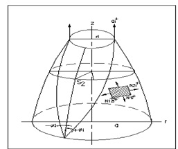 | Figure 2. Pressure Vessel Shell Element of ith Layer |
The stress resultants per unit length can be defined as follows: | (5) |
For shallow shells like pressure vessels, one can neglect  and obtain
  , as in a plate theory. The shear forces
  for a shell are derived by the moment and shear force equilibrium equations below.
  | (6) |
2.1.1. Stress Resultants on Cylindrical Surface of Composite Pressure Vessel
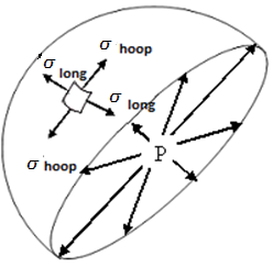
These stress resultants are assumed to be due only to an internal pressure, p, acting in the direction of r. A section of a cylindrical shell of composite pressure vessel is shown in Figure 3. The hoop (circumferential) stress  and the longitudinal stress
  are indicated in the figure.
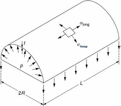 | Figure 3. Cylindrical shell |
Considering a cross-section of the shell perpendicular to its axis, we have This gives
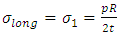 | (7) |
Considering equilibrium across the cut section, we have,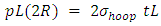 This gives
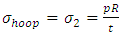 | (8) |
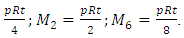
Considering the maximum shear stress theory, we have 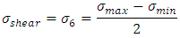 From the equations (4) and (5)
  and
and  Therefore
 | (9) |
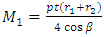
From the equations (5), the stress resultants can be derived by considering  for shallow shells and substituting equations (7), (8) & (9) in equation (2), gives the N1, N2, N6, M1, M2 and M6 as:
  ;
;  ;
; 
 From the equation (6), and derived formulas of M1, M2 and M6 for cylindrical shell, the stress resultants Q1 and Q2 can be derived as:
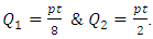
2.1.2. Stress Resultants on Hemispherical Dome Surface of Composite Pressure Vessel
A section of a hemispherical dome shell of composite pressure vessel is shown in Figure 4. The hoop (circumferential) stress  and the longitudinal stress (
 ) are indicated in the figure. Considering a cross-section of the shell perpendicular to its axis and also considering equilibrium across the cut section, we have
 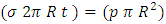 This gives
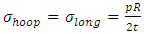 | (10) |
 | Figure 4. Hemisperical dome shell |
The longitudinal stress is equals to that of hoop stress hence by considering the maximum shear stress theory, we have 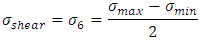 From the equation (10)
  This gives
 | (11) |
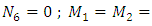
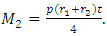
From the equation (5), the stress resultants can be derived by considering  for shallow shells and substituting equations (10), & (11) in equation (5), gives N1, N2, N6, M1, M2 and M6 as:
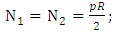
 From the equation (6) and derived formulas of M1, M2 and M6 for hemispherical shell, the stress resultants Q1 and Q2 can be derived as:
  . But
. But  should not be zero, because the shear forces will be present at junction of the dome and cylinder, at the end of the dome and at the junction of hoop and doily layers, so to predict the shear forces at these portions the dome is assumed to be discretized as small conical frustums as shown in figure 5. Hence further the stress resultants for the conical shell were developed.
 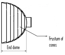 | Figure 5. Hemispherical dome descritized into conical frustums |
2.1.3. Stress Resultants on Conical Frustum Surface on Composite Pressure Vessel Dome
A section of a conical shell of composite pressure vessel dome is shown in Figure 6. The hoop (circumferential) stress  and the longitudinal stress
  are indicated in the figure. Considering a cross-section of the shell perpendicular to its axis at middle of both maximum and minimum radius, we have
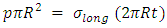 Where
Where 
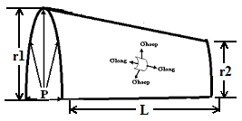 | Figure 6. Conical shell |
This gives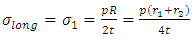 | (12) |
Considering equilibrium across the cut section, we have,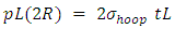 This gives
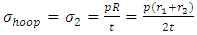 | (13) |
Considering the maximum shear stress theory, we have 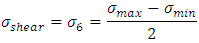 From the equations (12) and (13)
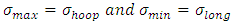 This gives
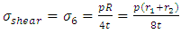 | (14) |
From the equation (5), the stress resultants can be derived by considering  for shallow shells and substituting equations (12), (13) & (14) in equation (5), gives N1, N2, N6, M1, M2 and M6 as:
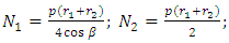

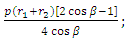
 ;
;  Where
Where  is slope of contour. From the equation (6), and derived formulas of M1, M2 and M6 for Conical shell; the stress resultants Q1 and Q2 can be derived as:
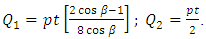
2.2. First Order-Shear Deformation Theory
First order-shear deformation theory (FOSDT) extends the kinematics of the classical lamination theory (CLT) by including a gross transverse shear deformation in its kinematic assumptions; i.e., the transverse shear strain is assumed to be constant with respect to the thickness coordinate. As in CLT, FOSDT also assumes each ply is in a state of plane stress condition but transverse shear stresses are not neglected. The constitutive relations for FOSDT were derived using lamina constitutive equations (15) and the equations (16). | (15) |
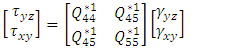 | (16) |
The general laminate Force-Deformation equations are defined as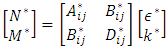 | (17) |
Where 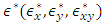 are mid-plane strains and
 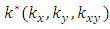 are mid-plane curvatures and the laminate stiffness coefficients
  are defined as.
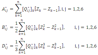 In addition to CLT equations in FOSDT the Shear Force-Shear Deformation are defined as.
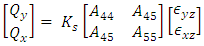 | (18) |
Where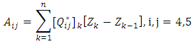 The analytical solutions of the composite Pressure vessel are obtained by using above equations.
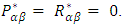
2.3. Third Order-Shear Deformation Theory
The classical laminate theory and the first order shear deformation theory are the simplest equivalent single-layer theories, and they adequately describe the kinematic behavior of most laminates. Higher-order theories can represent the kinematics better, may not require shear correction factors, and can yield more accurate interlaminar stress distributions. However, they involve higher-order stress resultants. The constitutive relations for any layer in the shell are in equation (19). The stress resultants are related to the strains by relations given in equation (20) & (21).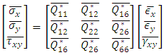 | (19) |
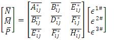 | (20) |
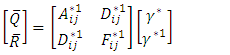 | (21) |
In which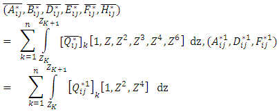 For Third order shear deformation theory,
 The analytical solutions of the composite Pressure vessel are obtained by using above equations.
2.4. Finite Element Analysis Using ANSYS Software
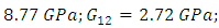
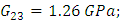
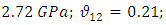
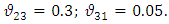
The study is analyzed by considering the entire pressure vessel with half cut section. The material data considered for the study are: 


 Loading and bounadary conditions are given separately to the models. The layered composite 3-D shell-281 shell element is a more developed element and has more capabilities to model filament wound layered structures. The model is revolved for 1800 and the analysis is performed. The domes are divided into zones and in each zone the material and geometrical properties are incorporated into the layers of the element. Since the composite shell is produced by helical winding
  and hoop winding, the shell is discretized into certain number of zones. Each zone is assumed to have constant angle of winding and thickness. The winding angle, axial length of the pressure vessel and radial contour are considered from table 1 for modeling in ANSYS. The shell is constrained at the both openings i.e. Uy=0 and symmetric boundary conditions on the cut edges of shell. A uniform internal pressure of 50 bar is applied on the inner surface of the shell. The axial direction in the analysis is considered as Y-direction and radial direction in X-direction.
3. Results and Discussions
3.1. Inter-laminar Transverse Directional Behaviour
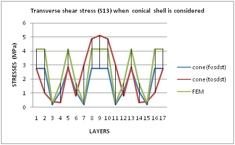
It is necessary to determine the distribution of the transverse shear stresses and transverse shear strains at the junctions of cylindrical and dome portions of a composite pressure vessel where hoop and doilies will meet together but were not continuous fibers. By using derived shear resultants Q for two cases; one is cylindrical case and another conical case, the transverse shear stresses and transverse shear strains at the junctions of cylindrical and dome portion were predicted. Due to different fiber orientation the transverse shear stiffness can change considerably from layer to layer. That causes an abrupt change of transverse shear at the layer interface, which cannot be matched by displacement functions with continuous derivatives. This deficiency gave rise to proposing layer-wise models. By observing the graph 1 and graph 2, finite element analysis and first order shear deformation shell theory shows linear variation of value and the same shape of graph in both assumptions, i.e., cylinder for cylindrical portion and cone for dome portion. These two theories (FEA & FOSDT) show maximum value of transverse shear stress (S13) at hoop layers on cylindrical portion as well as doilies on dome portion and minimum value of transverse shear stress (S13) was observed at 3rd, 7th, 11th and 15th layers (all are helical layers). FEA is having maximum value comparing with FOSDT. TOSDT shows the layer-wise variation in both the cases. Accordingly, TOSDT shows maximum value of transverse shear stress (S13) for middle layer of pressure vessel and minimum value of transverse shear stress (S13) for 4th layer and 14th layer (helical layers).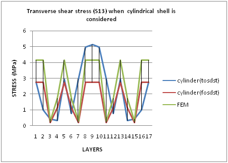 | Graph 1. Transverse Shear Stresses (S13) For Cylindrical Portion |
 | Graph 2. Transverse Shear Stress (S13) For Dome Portion When Conical Shell Is Considered |
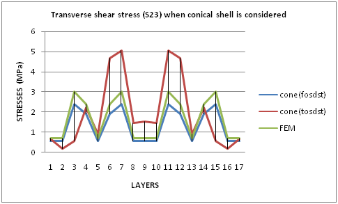
By observing the graph 3 and graph 4, finite element analysis and first order shear deformation shell theory shows linear variation of value and the same shape of graph in both assumptions, i.e., cylinder for cylindrical portion and cone for dome portion. These two theories (FEA & FOSDT) show maximum value of transverse shear stress (S23) at ± helical layers and minimum value of transverse shear stress (S23) was observed at hoop layers on cylindrical portion or doilies on dome portion. FEA is having maximum value comparing with FOSDT. TOSDT shows the layer-wise variation in both the cases. Accordingly, TOSDT shows maximum value of transverse shear stress (S23) for 7th layer and 11th layer (both are helical layers) of pressure vessel and minimum value of transverse shear stress (S23) for 2nd layer and 16th layer (both are hoop layers).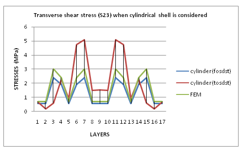 | Graph 3. Transverse Shear Stress (S23) For Cylindrical Portion |
 | Graph 4. Transverse Shear Stress (S23) For Dome Portion When Conical Shell Is Considered |
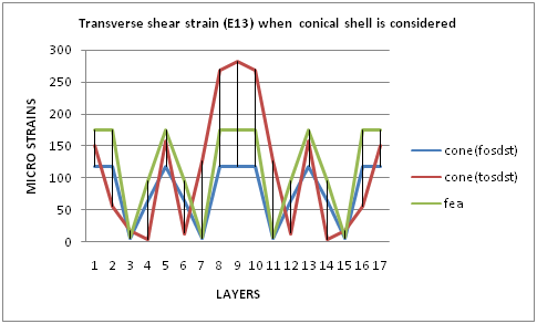
By observing the graph 5 and graph 6, finite element analysis and first order shear deformation shell theory shows linear variation of value and the same shape of graph in both assumptions, i.e., cylinder for cylindrical portion and cone for dome portion. These two theories (FEA & FOSDT) show maximum value of transverse shear strain (E13) at hoop layers on cylindrical portion as well as doilies on dome portion and minimum value of transverse shear strain (E13) was observed at 3rd, 7th, 11th and 15th layers (helical layers). FEA is having maximum value comparing with FOSDT. TOSDT shows the layer-wise variation in both the cases. Accordingly, TOSDST shows maximum value of transverse shear strain (E13) for middle layer of pressure vessel and minimum value of transverse shear strain (E13) for 4th layer and 14th layer (hoop layers).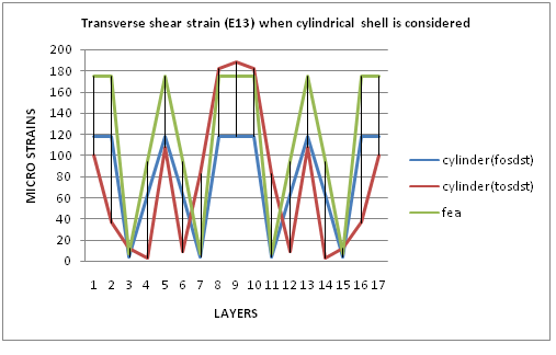 | Graph 5. Transverse Shear Strain (E13) For Cylindrical Portion |
 | Graph 6. Transverse Shear Strain (E13) For Dome Portion When Conical Shell Is Considered |
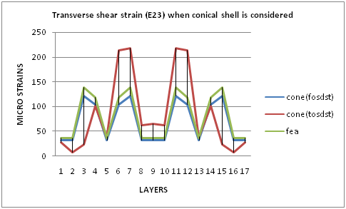
By observing the graph 7 and graph 8, finite element analysis and first order shear deformation shell theory shows linear variation of value and the same shape of graph in both assumptions, i.e., cylinder for cylindrical portion and cone for dome portion. These two theories (FEA & FOSDT) show maximum value of transverse shear strain (E23) at ± helical layers and minimum value of transverse shear strain (E23) was observed at hoop layers on cylindrical portion or doilies on dome portion. FEA is having maximum value comparing with FOSDT. TOSDT shows the layer-wise variation in both the cases. Accordingly, TOSDT shows maximum value of transverse shear strain (E23) for 7th layer and 11th layer (both are helical layers) of pressure vessel and minimum value of transverse shear strain (E23) for 2nd layer and 16th layer (hoop layers).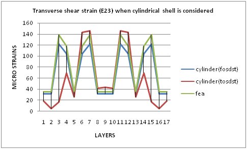 | Graph 7. Transverse Shear Strain (E23) For Cylindrical Portion |
 | Graph 8. Transverse Shear Strain (E23) For Dome Portion When Conical Shell Is Considered |
3.2. Finite Element Analysis of Composite Pressure Vessel
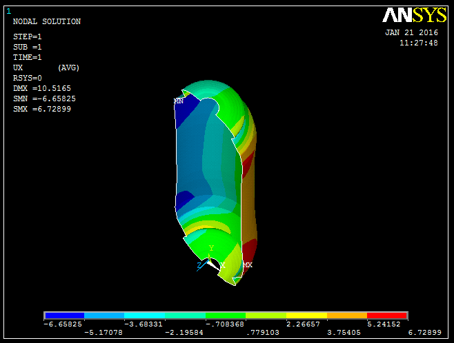
In the finite element analysis, Ux represents the radial deformations and Uy indicates the axial deformations of a composite pressure vessel. Figure 7 & Figure 8 shows the radial and axial deformations simulated by finite element analysis. The maximum radial dilations are computed on the cylindrical region with a magnitude of 6.7 mm and maximum axial dilations with magnitude of 9.5 mm as shown in figures 7 & 8. The estimated burst pressure values at various locations of composite pressure value ar computed by incorporating the progressive failure theory in TOSDT, shown in figure 9. In the analysis, the final bursting occurs at the cylinder- end dome juntions in the pressure value 62.6 bar. 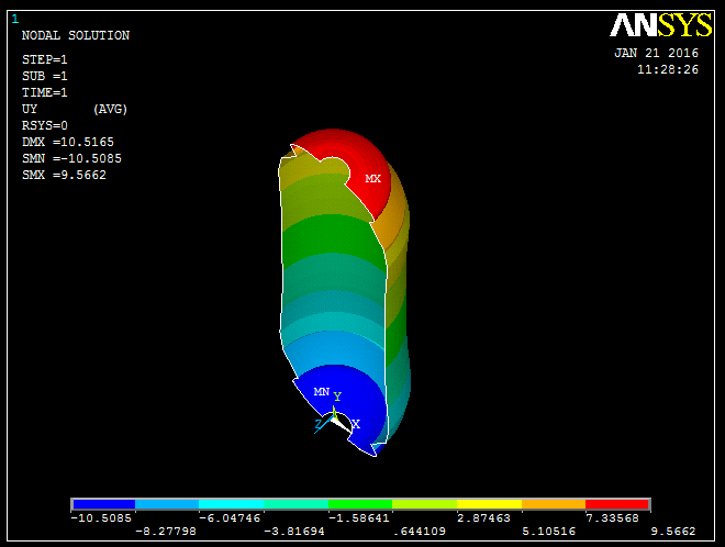 | Figure 7. Axial dilation of composite Pressure vessel at 50 bar pressure |
 | Figure 8. Radial dilation of composite Pressure vessel at 50 bar pressure |
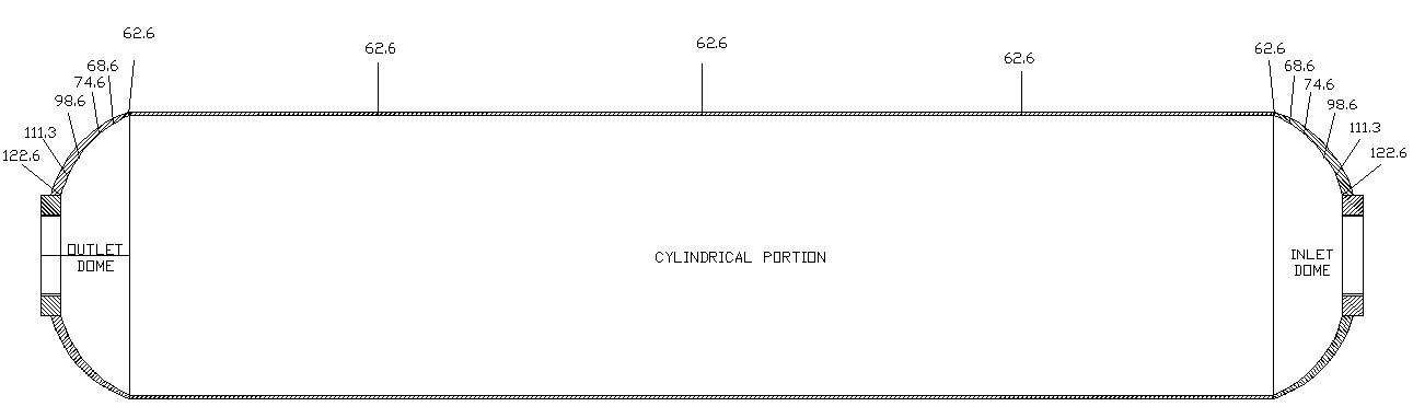 | Figure 9. Estimated Burst Pressure (Bar) Values At Various Stations Of The Shell by TOSDT |
4. Conclusions
The design approach for composite pressure vessel is based on netting analysis using E-Glass fiber and epoxy resin. Composite pressure vessel is designed by determining the thickness of shell, number of helical and hoop layers and plies sequence to be laid on the mandrel. The proposed analysis procedure mentioned in this study, could reduce the time required to design filament wound structures and can check whether the ply design is safe or not for the given input conditions. In the analysis, the final bursting occurs at the cylinder- end dome juntions in the pressure value 62.6 bar. The inter-laminar Stresses and Strains were predicted by using First Order Shear Deformation Theory (FOSDT), Third Order Shear Deformation Theory (TOSDT) and Finite Element Method (FEM). The transverse shear stresses and transverse shear strains may cause the de-lamination and failures at junctions or at pole openings.The TOSDT & FEA gives accurate results for the through-the-thickness stress response in regions of discontinuity such as cut-outs, holes, and boundaries. Moreover these theories do not require shear correction coefficients to rectify unrealistic variations of the shear strain/stress through the thickness. Because of the complexities, analytical solutions for the prediction of transverse/inter-laminar stresses exist for composite laminates with simple geometry, loading and boundary conditions. Therefore more emphasis has been placed on the use of numerical methods (FOSDST, TOSDST & FEA) when the composite laminate problem involves complicated geometry, loading and boundary conditions.
References
| [1] | Auricchio. F., Sacco. E. “Refined First-Order Shear Deformation Theory Models for Composite Laminates” Journal of Applied Mechanics, ASME, Vol. 70, pp. 381-390, (2003). |
| [2] | Beakou. A and Mohamed. A, “Influence of variable scattering on the optimum winding angle of cylindrical laminated composites”, Compos Struct, Vol.53, pp. 287-93, (2001). |
| [3] | Cheol-Ung Kim, Ji-HoKang, Chang-Sun Hong, Chun-Gon Kim“ Optimal design of filament wound structures under internal pressure based on the semi-geodesic path algorithm”, Composite structures, Vol.6, pp. 443-452, (2005). |
| [4] | Cho-chung, Liang, Hung-Wenchen and Cheng-Huan Wang, “Optimum design of dome contour for filament wound composite pressure vessels based on a shape factor”, Composite structures, Vol.58, 469-480, (2002). |
| [5] | Csonka. B. and Kozák. I., Mota soares and Mota soares. C.A., “Shape optimization of axisymmetric shells using a higher-order shear deformation theory”, Structural Optimization, Vol. 9, pp. 117-127, (1995). |
| [6] | HUANG. X., LU. G. “Buckling analysis of laminated circular cylindrical shells using a two-surface theory” International Journal of Mechanical Engineering Education, Vol. 30, No 2, pp. 171–183, (2000). |
| [7] | Jae-Sung Park, Chang-Sun Hong, Chun-GonKim, Cheol-Ung Kim, “Analysis of filament wound composite structures considering the change of winding angles through the thickness direction”, Composite structures, Vol. 55, pp. 63-71, (2002). |
| [8] | Kant.T. and Mallikarjuna. “A higher-order theory for free vibration of unsymmetrically laminated composite and sandwich plate~finite element evaluations”, Computers and structures, Vol. 32, No. 5, pp. 1125-1132, (1989a). |
| [9] | Kant. T. and Menon. M.P. “Higher-order theories for composite and sandwich cylindrical shells with co finite element”, Computers and structures, Vol. 33, No. 5, pp. 1191-1204, (1989b). |
| [10] | Latheswary. S, Valsarajan. K V, Rao. Y V K S. “Behaviour of Laminated Composite Plates using Higher-order Shear Deformation Theory” IE(I) Journal-AS, Vol. 85, pp. 10-17, (2004). |
| [11] | Madhavi. M., Rao K.V.J., Narayana Rao. K. “Design and Analysis of filament wound composite pressure vessel with integrated end domes”, Defense Science Journal, Vol 59, No.1, (2009). |
| [12] | Musthak Md, Madar valli P and Narayana Rao S, “Prediction of transverse directional strains and stresses of filament wound composite pressure vessel by using higher order shear deformation theories”, International journal of composite materials, Vol. 6(3), pp. 79-87, (2016). |
| [13] | Nagesh, “Finite element Analysis of composite pressure vessels with progressive degradation”, Defence Science Journal, Vol. 53(1), pp. 75-86, (2003). |
| [14] | Ngo Nhu Khoa, Tran Ich Thinh “Finite element analysis of laminated composite plates using high order shear deformation theory” Vietnam Journal of Mechanics, VAST, Vol. 29, No. 1, pp. 47 – 57, (2007). |
| [15] | Rastgaar Aagaah. M., Mahinfalah. M., Nakhaie Jazar. G., “Natural frequencies of laminated composite plates using third order shear deformation theory” Composite Structures, Vol. 72, pp. 273–279, (2006). |

 Abstract
 Reference
 Full-Text PDF
 Full-text HTML