Widayani1, Triati Dewi Kencana Wungu1, 2, Sparisoma Viridi1, 2
1Nuclear Physics and Biophysics Research Division, Faculty of Mathematics and Natural Sciences Institut Teknologi Bandung, Jalan Ganesa 10, Bandung, Indonesia
2Research Center for Nanoscience and Nanotechnology, Institut Teknologi Bandung, Jl. Ganesa 10 Bandung, Indonesia
Correspondence to: Widayani, Nuclear Physics and Biophysics Research Division, Faculty of Mathematics and Natural Sciences Institut Teknologi Bandung, Jalan Ganesa 10, Bandung, Indonesia.
| Email: |  |
Copyright © 2019 The Author(s). Published by Scientific & Academic Publishing.
This work is licensed under the Creative Commons Attribution International License (CC BY).
http://creativecommons.org/licenses/by/4.0/

Abstract
Several materials are known as anisotropic materials under external forces. This property is related to internal structure of the materials. An example of anisotropic material is wood. Normally, Young modulus of wood is described for three different directions: Longitudinal (L), Tangential (T) and Radial (R). A formula concerns with the influence of tensile angle on Young modulus of anisotropic materials is proposed based on a thin material model. The formula is derived using Hooke law and transformation matrix. Young Modulus at a specific tensile angle can be predicted using Young modulus values for tensile angle of θ=0° and θ=90°. The formula has been used to study the influence of tensile angle on Young modulus of single anisotropic materials (Oak red and Pine red) and series and parallel configuration in Longitudinal (L) direction of combination of Oak red and Pine red. The study shows that for anisotropic materials that have Young modulus Yx > Yy, and tensile angle is equal to 0° and 90° for x and y direction respectively, the Young modulus decreases as tensile angle increases. The decrease rate is higher in the smaller tensile angle region.
Keywords:
Anisotropic material, Young modulus, Tensile angle direction, Series configuration, Parallel configuration
Cite this paper: Widayani, Triati Dewi Kencana Wungu, Sparisoma Viridi, The Influence of Tensile Angle Direction on the Young Modulus of Single and Combination of Two Anisotropic Materials, International Journal of Composite Materials, Vol. 9 No. 2, 2019, pp. 33-38. doi: 10.5923/j.cmaterials.20190902.01.
1. Introduction
One of mechanical property of materials is stiffness, which can be represented by Young modulus. Each material has specific Young modulus. In general, Young modulus related to internal structure, i.e. to internal interaction between components within materials. Today, Young modulus of many materials has been measured and well recorded. These values often be used as references, i.e. in designing products.Several materials are anisotropic mechanically, i.e. they have different Young modulus values for different angle tensile directions. Anisotropic also can be caused by a preparation process, such as for steel [1]. Some natural materials such as woods and bamboos are known as anisotropic materials. These materials are plants which grow in vertical direction. Stiffness of woods and bamboos in vertical direction is different with their stiffness in other directions, so that Young modulus depends on fiber orientation [2].Wood is known to have different Young modulus in the Longitudinal (L), Tangential (T) and Radial (R) directions [3]. During a growth period, wood plants grow taller and the radius of the tree trunks get bigger. The schematic description of the directions L, T and R of wood is shown in the Figure 1. The L direction is the direction of wood fiber, that is, in the vertical direction of tree trunks. The growth of the wood trunk radius is influenced by the season, which results in the appearance of typical circular lines (named as growth rings) on its cross section. T is the direction of the tangent of the circular lines, and the direction of R is normal to the growth lines.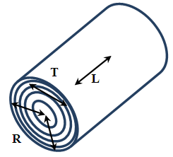 | Figure 1. Schematic figure of three directions of a wood trunk: L(Longitudinal), T(Tangential) and R(Radial) |
Bamboos also has different Young modulus in the vertical and horizontal directions [4]. Therefore, utilizing woods and bamboos must consider the orientation of the materials to get good performances of the products. Several studies have been carried out to explore the influence of tensile angle direction on mechanical property of materials. The studies were carried out both experimentally [2] and theoretically [5]. This paper concerns with a theoretical study of the influence of tensile angle direction on the Young Modulus of anisotropic materials. A formula of Young modulus as a function of tensile angle has been derived and applied to a single and combination of two anisotropic materials.
2. Theory and Models
2.1. Young Modulus of a Single Anisotropic Material
Basically, a material undergoes deformations under external forces, as in Figure 2. Normal tensile forces result in elongation, which can be accompanied by decreases in thickness. In this study, the decreases in thickness does not taken into account. In linear region, the normal force and the deformation follow Hooke law: | (1) |
Where σ is “stress” 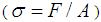 and F is normal force, A is surface area, and ε is “strain”
  , ΔL is elongation, L0 is initial length. Y is Young modulus.
 | Figure 2. Normal tensile stress causes elongation. Normal force F acted on the surface area A causes elongation ΔL from initial length L0 |
Naturally, a material is a 3D material, as with our space is 3D space. Mathematically, 3D space is represented by 3 ordinates. For example, a cube in Cartesian coordinates can be figured by ordinates x, y, and z. This study concerns with thin materials. The thin materials can be approached by a slice of a cube to get material in the form of a square, as shown in the Figure 3.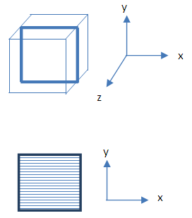 | Figure 3. Three ordinates (x, y, z) is used to describe 3D material (cube) and two ordinates (x, y) is used to describe a thin material (square) |
The thickness of this slice is far less than it lengths. For this form of materials, we can use two ordinates (x and y) to describe stress, Young modulus, and strain. Specifically, for anisotropic materials, the Young modulus in the x direction is different with that of in the y direction. Therefore, Hooke law can be written as follow:  | (2) |
 | (3) |
It is assumed that the decrease in y direction caused by σx is very small, and vice versa, so that it can be neglected. The Hooke law can be represented using matrix expression: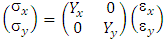 | (4) |
2.2. The Influence of Tensile Angle Direction on the Young Modulus
The response of an anisotropic material depends on the tensile angle direction. To discuss this, first we choose a pair of ordinates x and y as a reference. A vector OP, where the ordinates P are x and y, undergoes rotation with angle θ, now we have new vector OP’, with ordinates P, are x’ and y’ as shown by Figure 4.  | Figure 4. Vector OP undergoes rotation with angle of θ . Initial coordinate P (x, y) becomes new coordinate P’(x’, y’) |
The initial and new coordinates are related through a transformation matrix. The new ordinates (x’ and y’) can be derived from initial ordinates (x and y) through following transformation matrix [6].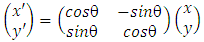 | (5) |
Basically, the Young modulus for before and after rotation should be the same: Yx=Yx’ and Yy=Yy’, and Hooke law also valid in the new coordinate: 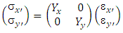 | (6) |
When a material experienced tensile stress at angle θ, it means that the stress direction is not at x’, nor at y’ direction; but it makes an angle θ to x’ as shown in Figure 5. It can be seen that the stress components in x’ and y’ directions depend on the angle θ. The x’ can be chosen as a specific direction, i.e. for the case of wood, it can be chosen as Longitudinal (L) direction.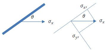 | Figure 5. Schematic figure of a material under stress directed at angle θ to a specific (i.e. Longitudinal) orientation. The stress components in new coordinate σx’ and σy’ are the projection of stress σx on the respected axis |
The stresses σx’ and σy’ are the projection of stress σx on the respected axis:  | (7) |
 | (8) |
Inserting (7) and (8) into (6) gives: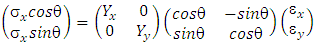 | (9) |
Solving the equation (9), gives the relationship between stress σx and strain εx: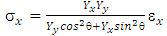 | (10) |
Regarding Equation (1), thus the Young modulus of anisotropic materials under tensile angle direction θ can be expressed as follow: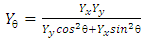 | (11) |
Noted that Yx and Yy are Young modulus at x and y direction, respectively. According to Equation 11, Young modulus of anisotropic materials under specific tensile angle direction can be calculated if the Young modulus Yx and Yy are known.
2.3. Young Modulus of Series and Parallel Configuration of Two Anisotropic Materials
Consider two anisotropic materials with the same dimension. There are two configurations in the combination of these materials: series and parallel. The configurations are seen in Figure 6.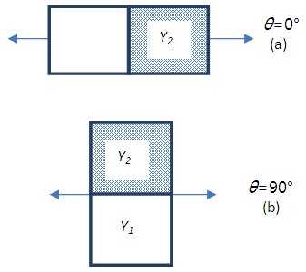 | Figure 6. Combination of two materials: (a) series configuration, (b) parallel configuration |
For series configuration, the total extension is equal to the addition of extension of material 1 and 2. The two materials experienced the same stress. The Young modulus of series configuration can be derived as follow: 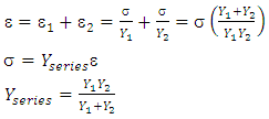 | (12) |
On the other hand, for parallel configuration, the total stress is equal to the addition of stress on material 1 and 2. It is assumed that the extension of material 1 is equal with that of material 2. Young modulus of parallel configuration can be derived as follow: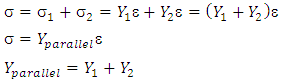 | (13) |
2.4. Series Configuration in Longitudinal (L) Direction of Two Anisotropic Materials
For anisotropic materials, there are several ways to combine them in series and parallel configurations. For an example, woods have different Young modulus for three different directions: Longitudinal (L), Tangential (T) and radial (R). Let consider two anisotropic materials that each have different Young modulus in the L and T directions. Series configuration in Longitudinal direction of two anisotropic materials is shown in Figure 7. 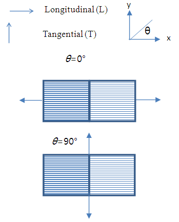 | Figure 7. Series configuration in Longitudinal (L) direction. The figure shows tensile angle direction of θ=0° and θ=90° |
The tensile angle at θ=0° is considered as the two materials arranged in series at Longitudinal direction. This leads to the tensile angle at θ=90° is related to parallel configuration of two materials in Tangential direction. Therefore, Young modulus of the series combination in Longitudinal direction for tensile direction θ=0° and θ=90° are: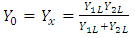 | (14) |
 | (15) |
Young modulus at any angles θ (0°<θ<90°) can be calculated using Equation (11).
2.5. Parallel Configuration in Longitudinal Direction of Two Anisotropic Materials
Figure 8 shows parallel configuration in Longitudinal direction of two anisotropic materials. The tensile at θ =0° is considered as the two materials are arranged in parallel at longitudinal direction, so that the tensile angle at θ=90° is related to series configuration of two materials in Tangential direction.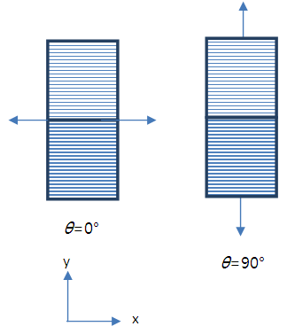 | Figure 8. Parallel configuration in Longitudinal direction. The figure shows tensile direction at θ=0° and θ=90° |
Therefore, Young modulus of the parallel configuration in Longitudinal direction for tensile angle direction θ=0° and θ=90° are: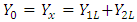 | (16) |
 | (17) |
Young modulus at any angles θ (0°<θ<90°) can be calculated using Equation (11).
3. Calculation Method
The formula of Young modulus (Equation 11) were used to analyse an anisotropic material model of woods. The materials are: single material of Oak red and Pine red, and series and parallel configuration of the combination of Oak red and Pine red. The Young modulus is calculated for several tensile angles: 0°, 15°, 30°, 60°, 75° and 90°. All the calculations were carried out using Microsoft Excel.In the calculation, the Young modulus data of Oak red and Pine red, are taken form a reference [7], which provide a very complete mechanical properties of woods that are growth in America. The Young modulus of wood normally obtained for compression. Woods are natural materials, so that their mechanical properties depend on growth condition such as weather, soil, moisture. The moduli values provided in the reference are average values. The moduli were determined using bending tests: a simply supported, center-loaded beam, on a span depth ratio of 14/1. In the calculation, the values are used without any correction for shear deflection. In this calculation, the Young's modulus along the longitudinal direction (YL) were for the woods with moisture content of 12% [7]. Young modulus along tangential direction (YT) were calculated using ratio YT/YL [7]. Figure 9 illustrates the L, R and T directions of a wood beam.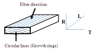 | Figure 9. Schematic figure of L, R and T directions of a wood beam |
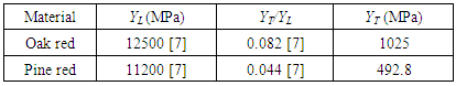
The Young modulus of Longitudinal and Tangential directions of Oak red and Pine red are shown in Table 1.Table 1. Young modulus of Longitudinal (L) and Tangential (T) directions of Oak red and Pine red
 |
| |
|
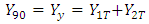
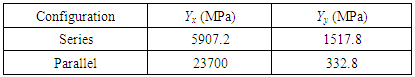
For analysis on combination of two materials that is carried out for series and parallel configuration of Oak red and Pine red in Longitudinal direction, the Young modulus Yx (θ=0°) and Yy (θ=90°) should be determined first using related formulas (Equation 14-15 and Equation 16-17). The calculated values are shown in Table 2.Table 2. Young modulus of series and parallel configuration in Longitudinal direction of the combination of Oak red and Pine red
 |
| |
|
4. Results and Analysis
4.1. The Influence of Tensile Angle Direction on the Young Modulus of Single Anisotropic Material
For study the influence of tensile angle direction on Young modulus of single material, Oak red and Pine red were chosen. Figure 10 and 11 show the stress-strain plot for Oak red and Pine red, respectively. In Figure 10 and 11, actually, the gradient of each curve is the value of Young modulus of respected tensile angle direction. It can be seen that Young modulus of the materials gradually decreases under changes of load angle, from Longitudinal to Tangential direction.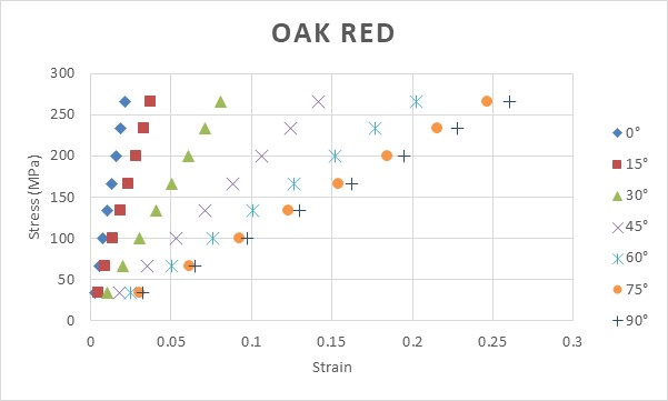 | Figure 10. Plot of stress-strain for Oak red for several different tensile angles. Tensile angles of θ=0° and θ=90° are related to Longitudinal (L) and Tangential (T) direction, respectively |
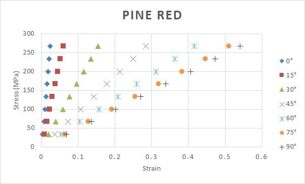 | Figure 11. Plot of stress-strain for Pine red for several different tensile angles. Tensile angle of θ=0° and θ=90° are related to Longitudinal (L) and Tangential (T) direction, respectively |
To see more clearly, plot of calculated Young modulus of Oak red and Pine red for several different tensile angle is depicted in Figure 12.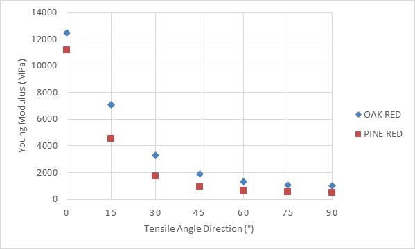 | Figure 12. Plot of calculated Young modulus of Oak red and Pine red for several different tensile angles. Tensile angle of θ=0° and θ=90° are related to Longitudinal (L) and tangential (T) direction, respectively |
As tensile angle increases, Young modulus decreases. The decrease rate is higher in the smaller angle. This happens because the materials are anisotropic materials. Using the formula Young modulus (Equation 11), it can be seen that when the same Yx and Yy is used, the Young modulus should have the same value for any direction, thus it means that a material with equal Yx and Yy is actually an isotropic material.
4.2. The Influence of Tensile Angle Direction on the Young Modulus of Combination of Two Anisotropic Materials
Combination of Oak red and Pine red was chosen to study the influence of tensile direction on Young modulus. Two configurations are used: series and parallel configuration in Longitudinal direction as shown by Figure 6 and 7, respectively. The Young modulus Yx and Yy which are related to tensile angle of θ=0° and θ=90°, respectively, for each configuration is as explained in the section “Theory and Models” and the values used are as in Table 2.Figure 13 and 14 show the stress – strain curves of series and parallel configuration in Longitudinal direction, respectively.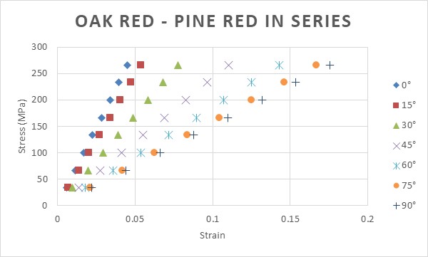 | Figure 13. Plot of stress-strain of series configuration of Oak red and Pine red in Longitudinal (L) direction for several different tensile angles |
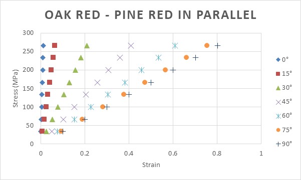 | Figure 14. Plot of stress-strain of parallel configuration of Oak red and Pine red in Longitudinal (L) direction for several different tensile angles |
Similar with the case of single materials, Young modulus of the materials gradually decreases as tensile angle increases. It is important to note that the calculation of Young modulus depends on the values of Yx and Yy for each configuration, which is correlated to the way to combine the materials. As in Table 2, in this study, the Young modulus Yx > Yy for every configuration.Figure 15 shows the plot of calculated Young modulus for series and parallel configuration of Oak red and Pine red in Longitudinal (L) direction for several different tensile angles.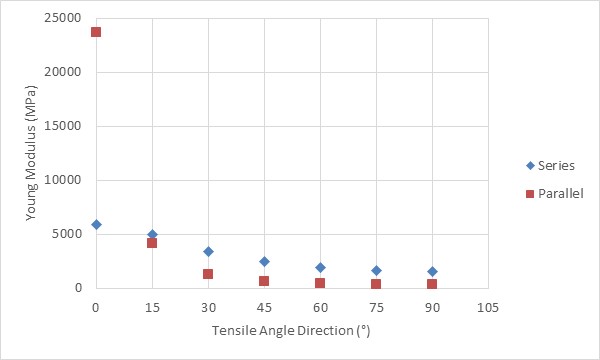 | Figure 15. Plot of calculated Young modulus of series and parallel configuration of Oak red and Pine red in Longitudinal (L) direction for several different tensile angles |
For tensile angle 0°, Young modulus of series configuration is far lower than that of parallel configuration. But as tensile angle increases, the Young modulus of parallel configuration decreases to lower values than that for series configuration for the same angles. As Young modulus actually depicts stiffness, the results means that even parallel configuration gives higher stiffness, but under any angle tensile (θ>0°), the stiffness will drop significantly.
5. Conclusions
A formula of Young modulus of anisotropic materials as a function of tensile angle direction has been proposed. The formula was derived using Hooke law and transformation matrix. The formula has been used to analyse the influence of tensile angle direction on Young modulus of single anisotropic materials (Oak red and Pine red), and series and parallel configuration in Longitudinal direction (L) of combination of Oak red and Pine red.For anisotropic materials, we choose ordinates x and y so that Yx > Yy, and tensile angle is equal to 0° and 90° for x and y direction respectively, Young modulus decreases as tensile angle increases. The decrease rate is higher for the smaller tensile angle region. For a combination of two anisotropic materials, the Young modulus Yx and Yy which are correlated to the way to combine, should be defined first before using the formula of Young modulus for a specific tensile angle.
ACKNOWLEDGEMENTS
The authors express gratitude to Institut Teknologi Bandung Indonesia, Ministry of Research, Technology and Higher Education, Indonesia, for funding the work via P3MI research fund for Nuclear Physics and Biophysics Research Division.
References
| [1] | Hsun hu, Elastic Properties of Cold-Rolled and Annealed Sheets of Phosporus Steel having High Normal Plastic An Isotropy Texture of Cryatalline Solids, 1980, Vol. 4, pp. 111-127. |
| [2] | Sripathy Malaiah, Krishna Vinayak Sharma, M Krishna, Investigation on Effect of Fiber and Orientation on the Properties of Bio-Fibre Reinforced Laminates, International Journal of Engineering Inventions, Volume 2, Issue 2 (January 2013) PP: 65-70. |
| [3] | Green David W.; Winandy, Jerrold E.; Kretschmann, David E. 1999. Mechanical properties of wood. Wood handbook: wood as an engineering material. Madison, WI: USDA Forest Service, Forest Products Laboratory, 1999. General technical report FPL; GTR-113: Pages 4.1-4.45. |
| [4] | Zehui Jiang, Fuming Chen, Ge Wang, Xing’e Liu, Sheldon Q. Shi and hai-tao Cheng, The Circumferential Mechanical Properties of Bamboo with uniaxial and Biaxial compression tests, BioResources, 7(4), 4806-4816, 2012. |
| [5] | Galina Kharkova, Olga Kononova, Andrejs Krasnikovs, Maris Eiduks, Edgars Machanovskis, Karlis Dzelzitis, ENGINEERING FOR RURAL DEVELOPMENT, Jelgava, 26.-27.05. 2011. |
| [6] | Mathematical methods in the Physical Sciences, Mary L. Boas, John Wiley and Sons, 3rd ed., 2006. |
| [7] | Ross, Robert J. 2010. Wood handbook: wood as an engineering material. Centennial ed. General technical report FPL; GTR-190. Madison, WI: U.S. Dept. of Agriculture, Forest Service, Forest Products Laboratory, 2010: 1 v. |

 Abstract
 Reference
 Full-Text PDF
 Full-text HTML