-
Paper Information
- Previous Paper
- Paper Submission
-
Journal Information
- About This Journal
- Editorial Board
- Current Issue
- Archive
- Author Guidelines
- Contact Us
International Journal of Composite Materials
p-ISSN: 2166-479X e-ISSN: 2166-4919
2019; 9(1): 7-15
doi:10.5923/j.cmaterials.20190901.02

Microcrack Detection in Composite Laminates at Early Stage of Thermal Cycling Using Moisture/Freeze/Dry Cycle
 Abstract
 Reference
 Full-Text PDF
 Full-text HTML
Shambhu Kumar Gupta, Mehdi Hojjati
Concordia Center for Composites, Concordia University, Montreal, Quebec, Canada
Correspondence to: Shambhu Kumar Gupta, Concordia Center for Composites, Concordia University, Montreal, Quebec, Canada.
| Email: |  |
Copyright © 2019 The Author(s). Published by Scientific & Academic Publishing.
This work is licensed under the Creative Commons Attribution International License (CC BY).
http://creativecommons.org/licenses/by/4.0/

Carbon-fiber reinforced polymeric composite materials have been widely used in space industry for manufacturing of spacecraft structures, satellite-panels and antennas. In space, composites are subjected to the periodic thermal cycling (TC) in which temperature ranges from −196 to 180°C, depending on operational condition. This range of temperatures causes various damages in composite, such as micro cracks, which in turn reduce the composite life cycles. Usually the micro-cracks become more evident/detectable when subjected to high number of thermal cycles. The aim of this work is to develop a technique to be able to identify the micro-crack initiation and its propagation at low number of thermal cycles. Experimental tests were conducted on composite specimens by subjecting the samples to thermal shock from -190°C (dipping in liquid nitrogen) to +150°C with different number of cycles. Then optical microscope was used to observe the micro-cracks. The microscopic results show that few micro-cracks appeared on the surface with low number of thermal cycles. Samples are then conditioned in boiled distilled water to become saturated (moisture procedure). A fast cooling, followed by sample drying in oven above water boiling temperature was performed and the samples were again examined under microscope. It was observed that the previous existing micro-cracks are more visible and also some new micro cracks surfaced. It is suggested that in order to detect the micro-cracks during the thermal cycling, moisture and heat can be used to accelerate the micro-crack growth and make them detectable even at low number of thermal cycles.
Keywords: Moisture/Freeze/Dry Cycle, Thermal cycling, Composites, Micro-crack initiation
Cite this paper: Shambhu Kumar Gupta, Mehdi Hojjati, Microcrack Detection in Composite Laminates at Early Stage of Thermal Cycling Using Moisture/Freeze/Dry Cycle, International Journal of Composite Materials, Vol. 9 No. 1, 2019, pp. 7-15. doi: 10.5923/j.cmaterials.20190901.02.
Article Outline
1. Introduction
- Reinforced polymeric composites with high strength and low density are an alternative candidate in lightweight structures in the aerospace industry. The most important advantages of composite materials are their high strength-to-weight ratio, low density, low coefficient of thermal expansion CTE, and their inherent high thermal/temperature resistance [1]. Replacing conventional metal alloys with composites, especially in satellites, aircraft and other automotive applications, results in considerable weight savings. The objective is usually to make a component which meets the design requirements and often with a low density for longer sustainability (longer time period). In recent years, structural parts manufactured with carbon/epoxy polymeric composite materials have been widely used in space and aircraft industries [2-4]. In the case of satellites, temperatures can often vary by near 270°C or above as they orbit around the earth [5-8]. A satellite in eclipse region, (Earth’s shadow) can experience temperatures as low as ‐190°C, up to 150°C in sunlit region. This phenomenon is known as thermal cycling in a cryogenic environment and is extensively found to induce micro-cracking, one of the main damage mechanisms of composite materials undergoing thermal cycling. Thermal stresses are generated during the temperature variation and curing processes of composite materials. But in addition, moisture can induces/produce different effects such as matrix properties reductions, swelling and expansion of matrix at the fiber-matrix interface that modifies the state of residual stresses and causes the micro-crack formation in composite materials [9-11]. It is known, that the moisture has significant effects on the physical and chemical properties of epoxy matrix as well as on their final performance of composite structures especially in their long-term utilization. The absorbed water usually reduces the glass-transition temperature (Tg) by plasticizing the polymer network and also affects mechanical performance and long-term durability of high performance composites. Manufacturing method is an influential factor in composite material properties. Composite structures are often cured in an autoclave to achieve the required space grade quality. However, curing large structures need access to large autoclaves, which is limited and expensive. So fabrication of large structures using OOA prepreg materials will result in huge amount of savings in manufacturing costs [12]. In OOA manufacturing method, presence of voids has been an issue due to lack of high pressure onto the laminate to eliminate the voids. As an alternative, a vacuum pump is utilized to exert a low pressure for minimizing the void content [13]. Many researchers have compared OOA prepregs with autoclave materials and found that the properties of laminates fabricated with the OOA prepregs can be the same as those fabricated with autoclave prepregs [14-15]. Cauberghs et al. [16] studied the OOA manufacturing of aerospace representative parts with complex shape using carbon/epoxy prepreg technology and compared them with autoclave parts. The mechanical performance of OOA prepregs including compression and bending properties was comparable to autoclave prepregs. Achieving uniformity in the thickness around tight corners was reported to be challenging for both techniques. Thermal cycling or thermal-shocking can be defined as a process of rapid changes in the temperature of the specimen from low to high or vice versa [10]. There is a lack of information in the literature and experiments need to be conducted to study the combined effects of thermal and moisture cycling loading. Space environments have a range of temperatures that cause damage in parts made of composite materials, which affect their performance and even threaten their ability to operate effectively for recommended time period. The second challenge is the orientation and lay-up of composite materials to delay the damage. Therefore, each orientation or lay-up has their own individual strength against environmental effects. The third challenge is how to analyze and simulate material behavior during test procedures, both analytically and numerically. Overall, here first priority will be given to identify the cracks and their propagation at low number of cycles, and then improve their life cycles or delay the damages with optimizing orientations/lay-up.
2. The General Concept for Microscopic Cracks Identification
- The motivation for this paper is to develop a method to make micro cracks visible and detectable at early stage of thermal cycling of a polymeric composite. The concern and necessity for such a method was raised by the space/aerospace industries. Currently most of the structures in satellites or supersonic aircraft are made of composite materials or a combination of polymer components and alloys. These structures can present significant challenges for manufacturing, but most challenges are found during their service life in fluctuating environments. Even as we consider that during manufacturing, structures contain acceptable defects or micro-cracks because of limitations in testing equipment. Micro-cracks usually become more visible and detectable at higher numbers of thermal cycling. Furthermore, the identification of micro-cracks which are considered negligible and their intensive propagation at early stage is mechanically rigorous but consequently has great potential for use in manufacturing design for complex space/aerospace applications in varying environments.Accelerated test method is used to save time and get the approximate results to predict the damage condition for long-term behavior in short period of time. Accelerated (temperature dependent) tests are justifiable if the accelerating parameter does not cause an artificial change in the aging mechanism. To verify this assumption, tests on a reasonably long time scale are necessary. The data in [21] indicated that 1000 h of accelerated aging at 70 °C caused a loss in flexural properties similar to 14-15 years in natural conditions. This is one of very few examples for which the effect of accelerated aging has been verified. Based on results of this example, proposed experimental methods of accelerated test were conducted and no damage was induced by accelerated parameters. The details procedure is described as follows.
3. Sample Preparation and Experiment
3.1. Material Selection
- The material used for this project was Cycom 5320‐1 manufactured by Cytec Engineered Materials Inc. which is a composite material system for manufacturing of primary structural parts in today’s aerospace industry. It is a toughened epoxy prepreg system specifically designed for OOA manufacturing. A woven fabric of 5‐harness carbon/epoxy satin prepreg (5HS) with the same resin system provided by Cytec was used to manufacture the samples, with total laminate thickness of ~3.5 mm [22].
3.2. Manufacturing of the Samples
- A cross-ply laminate with 8 layers of 5HS woven fabric (5-harness satin prepregs) were made. The plate was manufactured by the hand layup method and was vacuumed at a pressure of 0.1 MPa for one hour to eliminate the entrapped air and moisture. To track the plate temperature during the curing process and afterwards during the thermal cycling process, a k-type thermocouple was bonded to the edge of the mid plane of the laminate. Since the carbon fibers are conductive and by touching the thermocouple can cause false temperature reading, a release film was utilized to avoid contact between the prepreg and the thermocouple wire. To cure the composite laminate, the cure cycle recommended by the manufacturer for Cycom 5320‐1 material system was followed to cure the composite laminates [23]. The material was cured in a forced air circulation oven. A vacuum pump was used to pull the vacuum inside the layup bag. In order to accurately measure the laminate temperature during the cure and avoid the temperature delay between the oven temperature and plate temperature, the other end of the thermocouple already embedded in the laminate mid‐plane was taken out of the oven and used for data acquisition system. It was assumed that once the center ply of the laminate was within ±5°C of the desired temperature, all plies of the laminate had reached to the final temperature. Figure 1(a)-(b), shows OOA set-up and the cure cycle for the composite plate. As shown in this figure, the oven temperature was ramped from the room temperature to 120°C and held at this temperature for 3 hours to cure the epoxy. Then it was raised to 177 °C and maintained for 2 hours for the post‐curing, and finally the plate was allowed to cool down to room temperature. All the temperature changes occurred at a ramp rate of 0.6–2.8°C/min (Figure 1b).
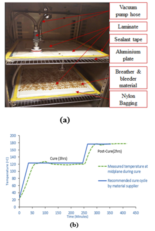 | Figure 1. a) Manufacturing set-up for OOA curing inside oven, b) Measured data and recommended cure cycle by material supplier |
3.3. Samples Characterization before Test
- DSC test was performed on the cross-ply fabric composite plate to obtain the degree of cure. Five samples were cut from different areas of the cross-ply fabric plate in order to have an average representative of the whole plate. Figure 2 shows the DSC heat flow signal for both uncured prepreg and cured laminate as a function of temperature. A linear integration of the area under the heat flow curve was used to calculate the total heat of reaction for both uncured and cured materials, which resulted in 166.1 J/g for the raw prepreg and 3.33 J/g for the cured laminate. Based on the data obtained from DSC graphs, the average degree of cure for the cross-ply fabric laminate was about 98%, which indicate a good curing process. It should be mentioned that the degree of cure for the plate was calculated as the average value of five different samples per category.
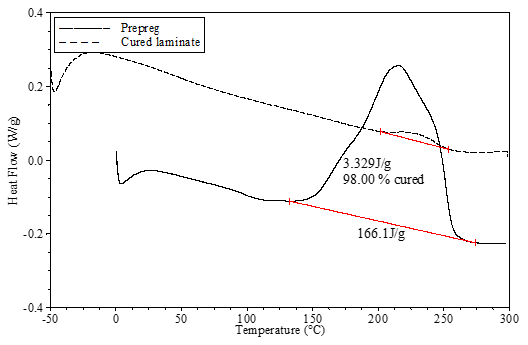 | Figure 2. Heat flow of uncured prepreg and cured laminate for cross-play fabric laminate obtained from DSC |
3.4. Thermal Cycling
- Thermal cycling was applied on the samples with dimensions corresponding to the width, length and thickness of 30×12×3 mm respectively, using a “thermal shock” method [22]. The samples were dipped in liquid nitrogen (‐195°C) for a period of 2 min and then exposed to room temperature (20°C) for a period of 5 min. Then the samples are heated up inside the oven to 150°C and maintained for 10 minutes as shown in Figure 4. This procedure will be repeated for up to 10, 50 and 100 cycles as shown in the Figure 3. Selected samples were taken under microscope after thermal cycles at 50 and 100. One side of the every sample was polished to make smooth surface for microscopic inspection. Different cross-sections were marked for the inspection of the laminates layers, micro-cracks, voids, resin rich area and their locations inside layers or tows.
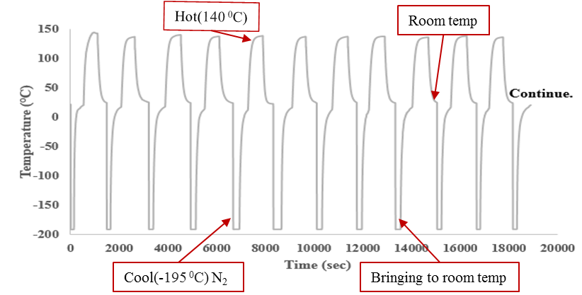 | Figure 3. Thermal cycle time steps, with Temperature cycle vs. time for 10+ thermal cycles |
3.5. Moisture/Freeze/Dry Cycle
- As of 100th thermal cycle done, an accelerated moisture/Freeze/Dry Cycle was designed and developed. It was assumed that the accelerated moisture test cause a very similar moisture response in the material as the baseline environment, but in a much shorter time. Similarly, the accelerated thermal cycle is predicted to cause thermal micro-cracking damage equivalent to that caused by the baseline environment in a much lower number of more intense thermal cycles. After applying a number of thermal cycles, the specimens are immersed in distilled water in a glass vessel. Then the glass vessel was immersed in a glass container which holds heated oil with the desired temperature which is controlled by heater from the Heidolph MR Hei-Standard Company (Figure 4). In order to measure the amount of water absorbed within each samples, the specimen weight has to be measured periodically by an analytical balance (Sartorius Company) which is accurate to ~0.1 mg. Before weighing, the specimens had been wiped out with a paper towel and dried for approximately 1-2 min to remove any excess surface moisture and to avoid any error. The weight and conditioning time should be recorded to calculate the moisture content.
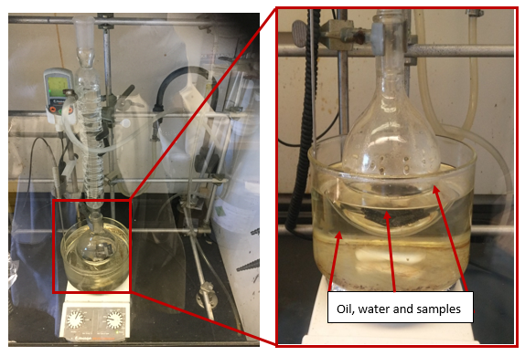 | Figure 4. Moisture set up |
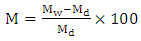 | (1) |
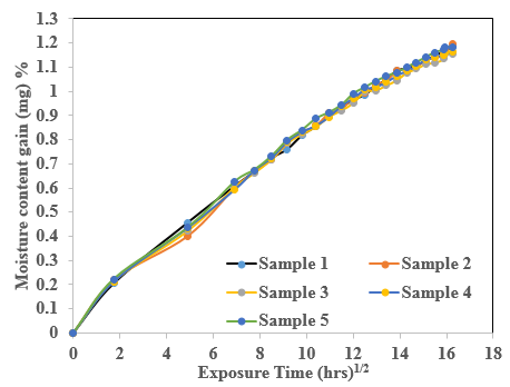 | Figure 5. Weight Gain of the samples as a Function of time |
3.6. Freeze/Dry Processing
- Freezing and drying processes are used to open more cracks as saturated samples are filled with water that expand over water freezing and boiling point temperatures. After moisturization cycle, specimens are kept in liquid nitrogen for freezing them and again weight was measured. After freezing, the specimens are analyzed under microscope and then they were taken into the oven at 110°C until their weight loss has stabilized and no further weight loss of the sample could be observed. This condition of the specimens is referred to as dry. Onset cracks developed by thermal cycle are saturated faster (during saturation processes) that help to accelerate crack propagation. These saturated samples are immersed in liquid nitrogen to freeze the saturated water in their own cavity or over void surfaces. Initial cracks are propagated faster during drying processes as saturated liquid expand their volume under increasing temperatures. Again, samples are needed for the purpose of crack investigation using optical microscope. Those samples are analyzed after moisture cycle to check the new crack initiation and propagation during wet cycles, and afterwards they are analyzed for freezing and dried cycles.
4. Results and Discussion
- The cross-sectional regions in each sample were examined under microscopic with 10-20X- magnification to track the cracks/damage in the entire sample and to detect the presence of micro-cracks. After this, every single layer were observed at specific locations for analysis of the path of the crack. During image analysis, we were also focused on crack onsets, which appear in the form of voids, which would result in cracks/delamination on the inner and outer ply of the composite laminate. Figure 6(a) shows selection of cross-sectional area, here no micro-cracks are visible. There are some void that could be the cause for the cracks initiation under thermal cycles. It can be observed that after 100th thermal cycles, the cracks become slightly more visible (Figure 6(b)). It does not mean that the micro-cracks appeared suddenly near 100th cycles. It could be there but as residual stresses increased by “thermal shock” like cooling and heating, aided to open the shield surface as a micro-crack.
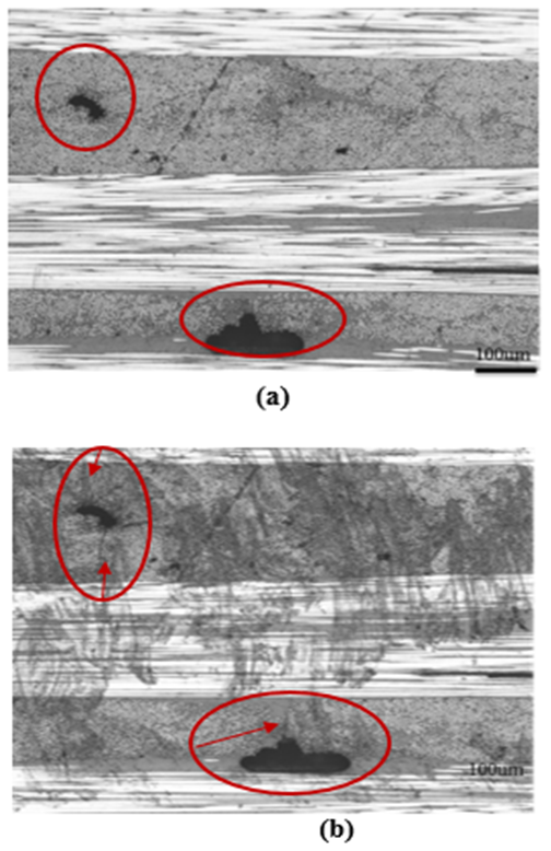 | Figure 6. Micrograph and crack detection a) before thermal shocking, b) after 100 thermal cycles |
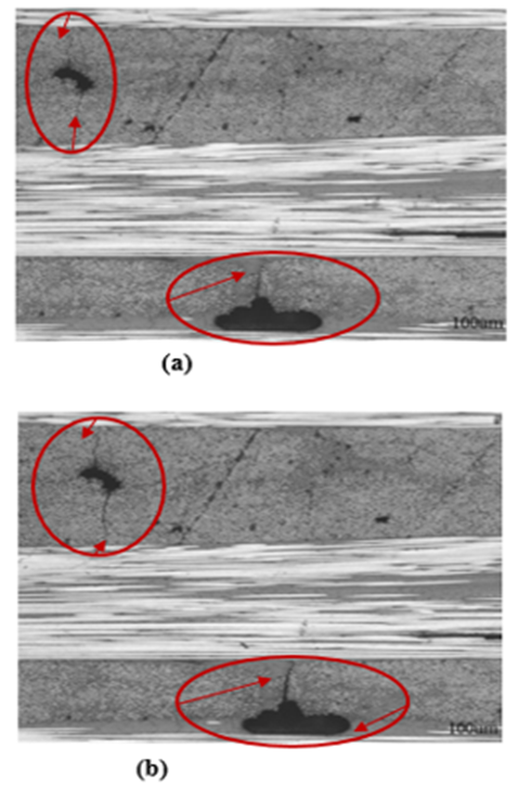 | Figure 7. Crack detection a) after moisture saturation and freezing and b) after drying |
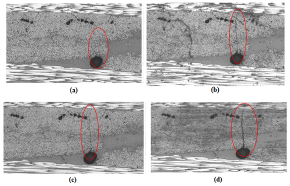 | Figure 8. Micro-cracks formation from the void surface (a) before TC (b) after 100 TC (c) N2 treatment and (d) Dry in oven |
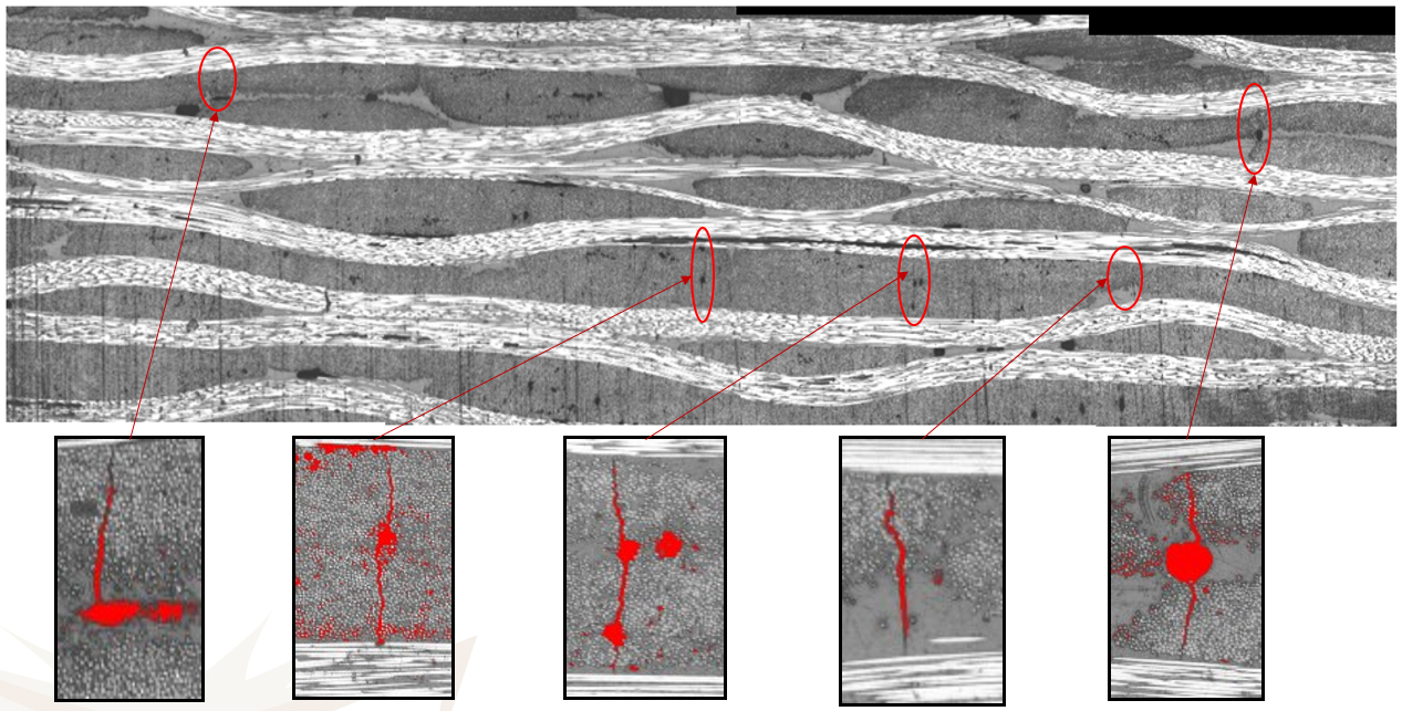 | Figure 9. Effect of Void on Micro-Cracks Formation and Propagations |
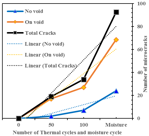 | Figure 10. Number of cracks with TC and moisture |
4.1. Interlaminar Shear Strength ILSS Results
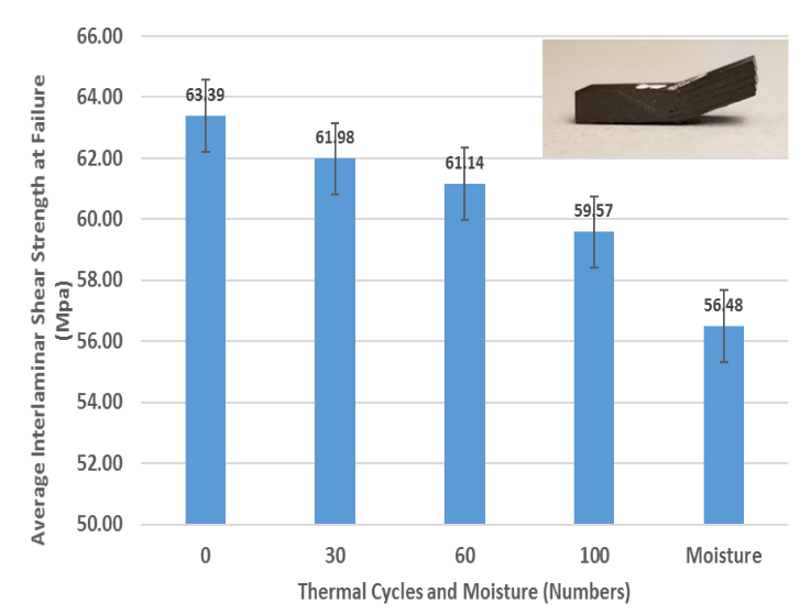
- To investigate the effect of microcracks on the material properties, ILSS test are conducted after different number of thermal cycles as well as after the moisture cycle to compare their strength. Figure 11 shows the variation of the ILSS of original carbon/epoxy composites versus the samples that are conditioned under different thermal cycles and also with the sample which went through moisture/freeze/dry cycle. The ILSS of the cross-ply fabric samples show that as the number of thermal cycles increases from 0 to 100, ILSS of the composites gradually decreased from 63.39 MPa for the unexposed sample to 59.57 MPa for the 100‐times‐cycled sample. ILSS of this sample (100-cycled sample) after exposure to the moisture/freeze/dry cycle reduces to 56.48 MPa.
 | Figure 11. Interlaminar shear strength with respect to thermal cycle and moisture cycle |
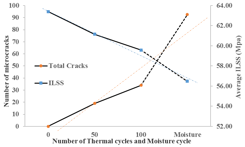 | Figure 12. Microcracks numbers and strength variation with thermal and moisture cycles |
4.2. Elastic Properties after Thermal Cycle and Moisture/freeze/dry Cycle
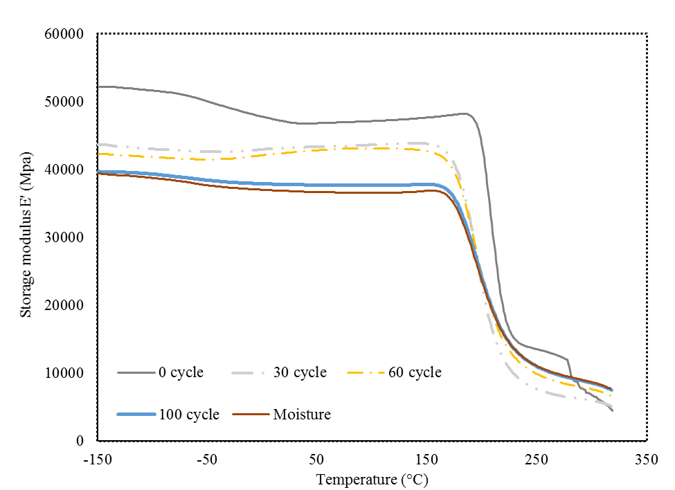
- Dynamic Mechanical Analyzer DMA has been used to study the effect of thermal cycle and moisture/freeze/dry cycle on the elastic and damping properties of composite. Figure 13 shows the variation of storage modulus E′ of the cross-ply composite with respect to temperature for samples subjected to the different number of cycles. The storage modulus at room temperature tends to significantly decrease from 0 to 100 thermal cycles, showing that the majority of damage and microcrack formation and propagation happen within this range. There is not much difference between the elastic modulus of the 100-cycled samples with and without moisture/freeze/dry cycle. One reason could be that the moisture/freeze/dry cycle may cause propagation of the existing microcracks on the surface (and therefore makes them more visible) but apparently has no contribution in creation of new microcracks, particularly inside the laminate.
 | Figure 13. Effect of thermal cycling and moisture/freeze/dry cycle on storage modulus of cross-ply fabric laminate |
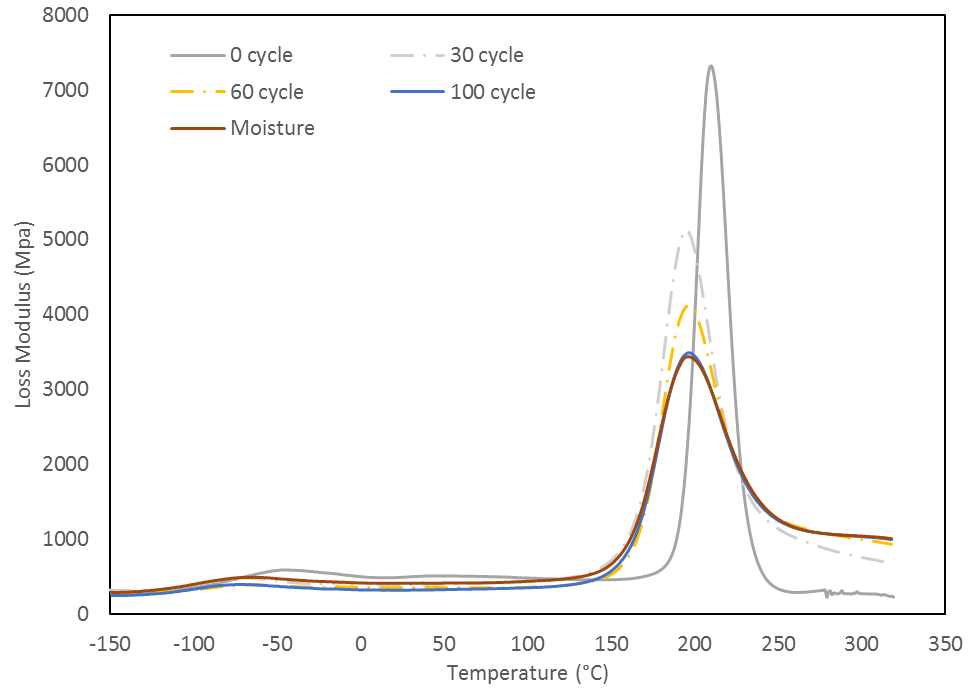 | Figure 14. Effect of thermal cycling and moisture cycle on the loss modulus of cross-ply fabric laminate |
5. Conclusions
- Identification of microcracks at early stage of thermal cycling is difficult due to their small sizes. In this study, an experimental method called moisture/freeze/dry cycle is developed in which, the samples after thermal cycling are dipped into boiled distilled water to introduce moisture into matrix and voids and cracks. After which the sample is frozen in the liquid nitrogen for about 5 min, then heated up to 110°C in order to remove the moisture content. Introduction of the moisture to the samples after the thermal cycling changes the matrix properties. Moisture can penetrate inside the void and cracks. The induced frozen step of the developed method helps in the transformation of absorbed water inside the voids to the solid form (ice). When the samples are dried, the ice formed during the previous step tends to evaporate. Freezing and evaporation of water inside the void and cracks jointly with reduction of the matrix stiffness due to the moisture absorption helps the crack moves and propagates. It was observed that the previous existing micro-cracks are more visible and also some new micro cracks surfaced. It is demonstrated that, to detect the micro-cracks at low number of thermal cycles, moisture and heat can be used to accelerate the micro-crack growth and make them more detectable. Thus, the damages can be detected at early stage of its formation, which saves time.
ACKNOWLEDGEMENTS
- The authors would like to acknowledge the financial support from the Natural Sciences and Engineering Research Council of Canada (NSERC), Consortium De Recherche Et D’innovation En Aérospatiale Au Québec (CRIAQ), MDA Corporation and Stelia North America.