S. W. Chung1, G. S. Ju2
1University of Utah, Salt Lake City, USA
2Yeung Nam University, Tae Gu, Korea
Correspondence to: S. W. Chung, University of Utah, Salt Lake City, USA.
| Email: |  |
Copyright © 2018 The Author(s). Published by Scientific & Academic Publishing.
This work is licensed under the Creative Commons Attribution International License (CC BY).
http://creativecommons.org/licenses/by/4.0/

Abstract
Various spherical shell theories of hybrid anisotropic materials are developed and formulated by asymptotic integration approach. The behavior and characteristics of the theory can be significantly different from the classical isotropic materials to modern anisotropic materials. The spherical shell theory of hybrid anisotropic materials can be compared to the method of simulation solutions from already formulated cylindrical shell theories by authors. The spherical shell model is a 50 Degree spherical shell of laminated materials, which are basically anisotropic materials different properties and different thicknesses of each lamination. Starting from already established theories hybrid anisotropic cylindrical shells by authors, we invented similarities between the cylindrical and spherical shell theories to be able to predict pre-bucking or tensile deformation patters as well as stresses and strains.
Keywords:
Spherical Coordinates, Laminated Shell wall, Hybrid anisotropic materials, Asymptotic integration method, Membrane Theory
Cite this paper: S. W. Chung, G. S. Ju, A Spherical Shell Theories of Hybrid Anisotropic Materials, International Journal of Composite Materials, Vol. 8 No. 4, 2018, pp. 97-104. doi: 10.5923/j.cmaterials.20180804.03.
1. Introduction
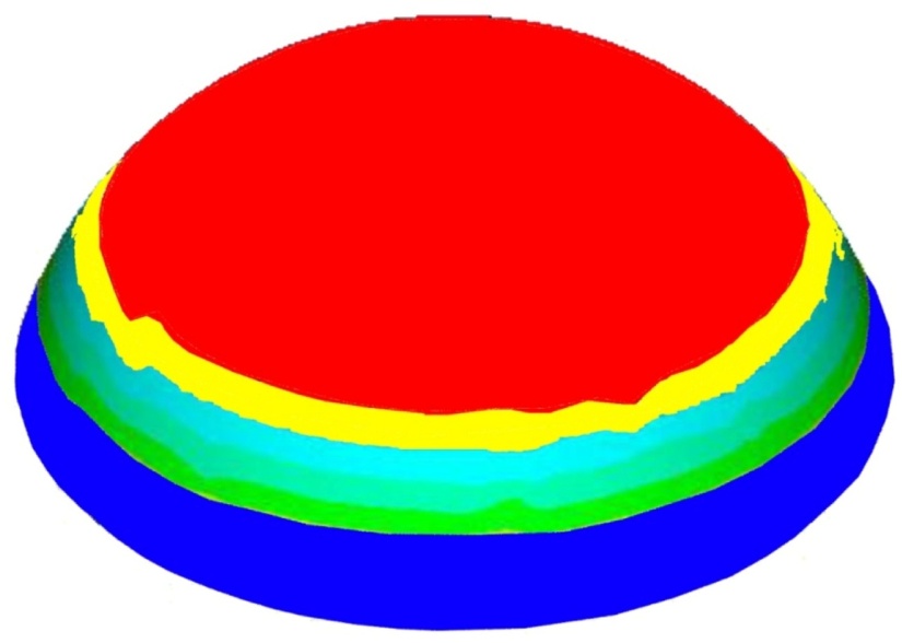
Long span gymnasium domes, high pressure liquid oxygen storage tank, human residents on the moon land are all spherical shells. We will use high strength, very light composite materials, which will take heavy snow load and high internal pressure loads or combination at the same time.The loading conditions can be classified as follows:1) Snow load and its own dead load2) External Pressure3) Internal Pressure4) Combination of all above loadsThe possible deformations will be subjected to the loading conditions but it will also be deformed arbitrarily to certain loading magnitudes and we can classify as follows:1) Axi-symmetric pattern with respect to the vertical axis2) Axi-asymmetric pattern with respect to the vertical axis, as shown in Figure 2.3) Axi-symmetric pattern with respect to the horizontal axis.4) Axi-asymmetric pattern with respect to the horizontal axis.5) Combination of the above as shown in Figure 3.Depending on which conditions of loading or deformation we select the theory and governing equations can be simple or very lengthy. We will choose the most complicated pattern and then reduce down to simplified cases.A typical configuration of dome structures is as shown in Figures (1), (2) and (3) where it was initially designed to take the gravity or snow type load. Due to load the loads are taken by upper portion of the dome where red colored portion of the dome, being maximum at the peak then gradually reduced.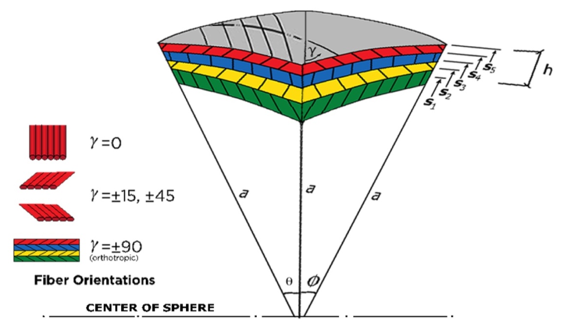 | Figure (1) |
 | Figure (2) |
 | Figure (3) |
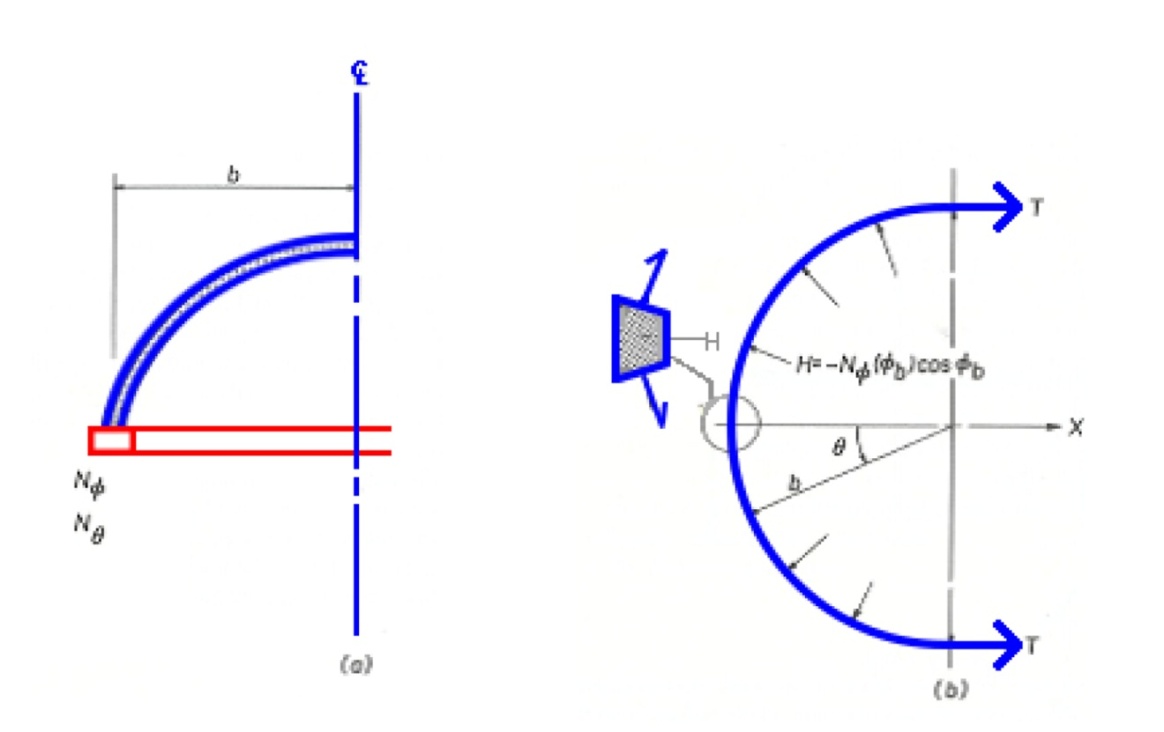
A dome not including latitudes less than 50 Degree does not develop significant hoop tension.From the generalized coordinate system of doubly curved surface where rφ and rθ meridian and circumferential radii of curvature respectively, we can reduced the coordinate systems as follows:Cylindrical: rφ = a, rθ = œSpherical: rφ = a and rθ = aWhere rφ is radius in meridional direction (Vertical) and rθ, the radius in circumferential direction (Horizontal).We can find similar pattern of deformation of spherical shell as the cylindrical shell as Figure (4) shows.Also the transition belt of 50 Degree where compressive membrane stress due to the gravity type vertical loading.For anisotrophic materials behaviors are same except some variations due to the material orientation.
2. Coordinate System and Geometric Configuration of a Sphere
Here we will use a typical spherical coordinate system as shown in Figure 1, where r, θ, φ are radial, horizontal and vertical coordinates respectively and r is a distance from the center of sphere to a point at outer surface before or after the deformation, θ and φ are angular quantities in horizontal and vertical direction respectively.See Figure (1). For dome structures of conventional materials, we normally take the supporting rings at the angle 50 Degree in meridional coordinate, as shown in Figures (3) and (4).Meridionaly measured from the vertical axis as shown in the Figures (2) and (3). We can then go back to the basic stress strain relations of anisotropic materials in all possible directions as follows: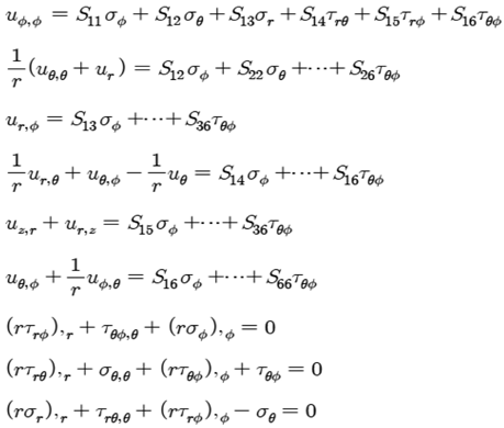 | (1) |
In the above equations, the first six equations are stress strain relations in r, θ, φ directions and the last three equations are equilibrium equations of basic anisotropic element. For the element complete anisotropy of the material is allowed for and there are thus 21 independent material constants. We are not allowed to illuminate any of those components, since the material properties are dependent on the manufactures set up and different gravity environment in case of aerospace vehicles. Also the compliance matrix is symmetric, Sij is the same as Sji, and the components can be expressed in terms of engineering constants as follows: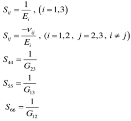 | (2) |
In equation (2) the Ei’s are the Young’s moduli in tension along the i – direction andEquation (2) implies anisotropic property of the material only, material to be non-homogeneous, different properties of each layer of the shell, we will allow the material property variation in the radial direction as follows: | (3) |
The above equation is unique and different from most of conventional theories.Figure (4) indicates good comparison of the mode of deformation between spherical and cylindrical shells, being 3rd mode in longitudinal and circumferential directions of cylindrical and meridional and circumferential directions of spherical shell.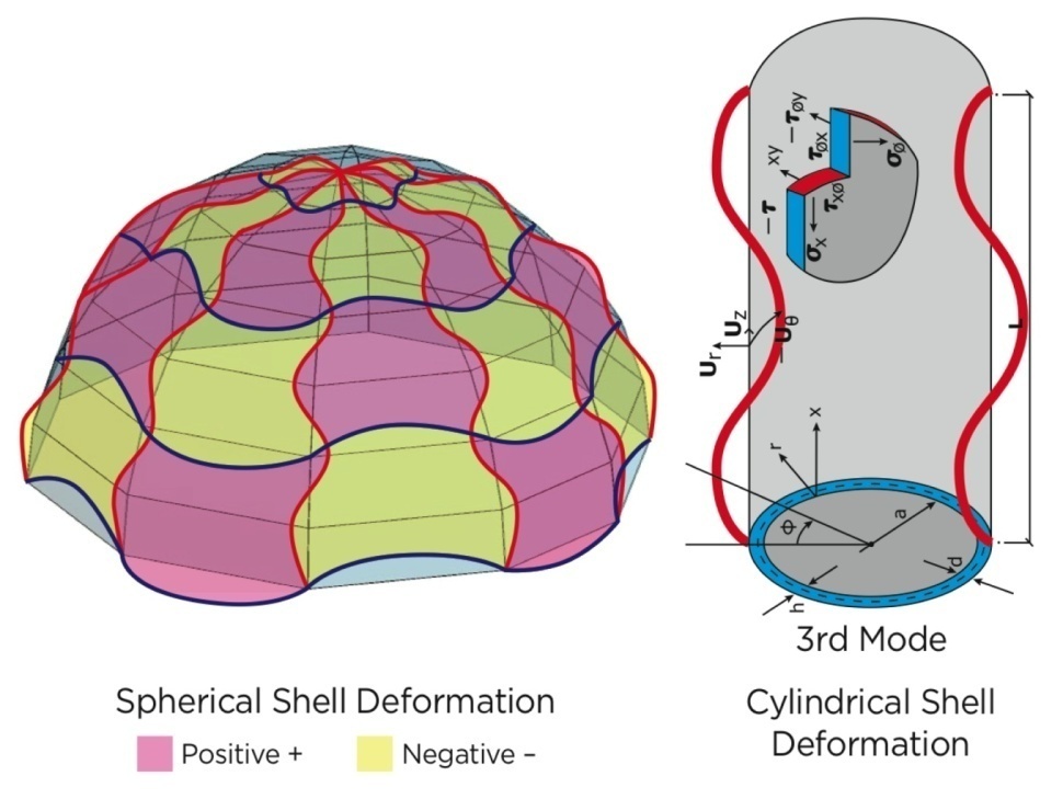 | Figure (4) |
We now need to transform the angle of major elastic properties to desired geometric directions, which is identified as.The standard transformation equations are as follow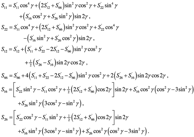 | (4) |
3. Formulation of Spherical Shell Theory of Anisotropic
MaterialsConsider a non-homogeneous, anisotropic volume element of a spherical body with meridional (angular), circumferential (angular) and radial coordinates being noted as a, θ, r, respectively as shown in Figure (1) and subjected to all possible stresses and strains.Here, a is the inner radius, h the thickness and r the distance from the center to outer surface. | (5) |
where β is  (3.14159 - - -).Here we should introduce a quantity of total thickness divide by inner radius as follows:
 | (6) |
And because we use very thin materials compared to the radius. | (7) |
The following equations are equilibrium and stress strain relations of the element.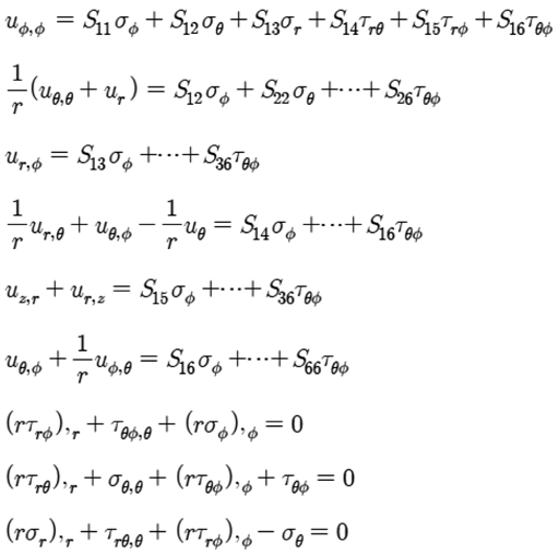 | (8) |
By utilizing the above thinness property of Equation (7), we can obtain the first system of equations of “thin shell” theory and we will call it the first approximation system. We can also obtain stresses and displacements of each layer of thickness coordinate, that can be an advantage of the procedure among others. In the following section, the thin shell theories for different combinations of length scales will be derived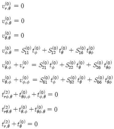 | (9) |
In the above equations super script such as (0) is the first approximation and sub script vr, θ indicates partial differentiation of vr with respect to θ.Then can then apply the above non-dimensional variables to the Equations (1), (2) and (3) of above to obtain the non-dimensional systems of equations as shown in Equation (5).
4. General Shell Deformation Patters of a Sphere
Here we expect the most general deformations are axi-asymmetric pattern in both meridional and circumferential directions as shown in Figure (4). The patterns are well compared with cylindrical shell systems.a : Inside Radius of Sphericall Shellh : Total Thickness of the Shell Walld : Distance (thickness) from Inside radius to mechanical neutral surfaceSi : Radius of Each Layer of Wall (I = 1, 2, 3 -- - to the number of layer) : Circumferential Length Scale of cylindrical shell to be definedEi : Young’s Moduli in I DirectionGij : Shear Moduli in i-j FaceSij : Compliance Matrix of Materials of Each Layer r : Radial Coordinate
 : Circumferential Length Scale to be definedθ: Angle of Fiber Orientationσ : Normal Stressesε : Normal Strainsφ, θ, r : Generalized Coordinates in Meridional, Circumferential and Radial Directions Respectively
 : Shear Stressesεij : Shear Strains in i-j Faceλ ; Shell Thickness / Inside Radius (h/a) Cij : Elastic Moduli in Generalφ, Y : Non Dimensional Coordinate System in Meridional,Circumferential and Radial Directions RespectivelyTable 1 List of Symbols
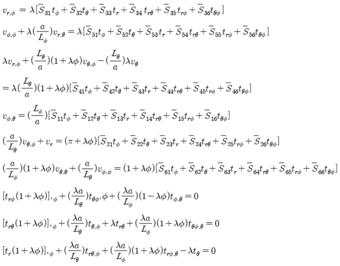 | (10) |
Lφ and Lθ are representative circular distance in meridional and circumferential distance respectively.Next we must obtain total in-plane forces and moments by following integrations.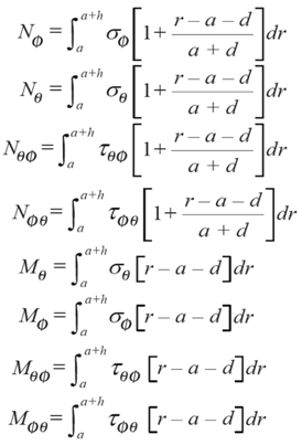 | (11) |
5. Discussion
The governing equations of the most general spherical shell of 50 Degree geometric boundary conditions are derived as shown in Equations (9) and (10). The governing equations will compromise laminated anisotropic materials in nature. In order to test the validity of the theory we applied the simplest theory of the equations which are membrane theory. The computations of governing equations and applying the relevant boundary conditions indicated the major elastic pattern angle is 60 Degree in lamella pattern is the strongest.
6. Conclusions
Mathematical formulation and governing equations of spherical shell of hybrid anisotropic materials are derived by means of asymptotic integration methods. The geometric boundary conditions we chosen are simply supported at the angle 50 Degree, following the most general dome roof patterns. Because it is the most recent development of the theory for hybrid anisotropic materials, we may require further applications of the equations to verify the theory.The use of the theory for composite materials is unlimited.Deep under water human oasis, human dwelling dome structure on the Moon land and large diameter gymnasium structures are only some of the examples. The use is unlimited.
ACKNOWLEDGEMENTS
The research was sponsored by Summit Partners in Menlo Park, California, USA and graciously acknowledged.
References
| [1] | Love, A. E. H., A treatise on the mathematical theory of elasticity, 4th edition. New York, NY, USA: Dover Publications, 2011. |
| [2] | Donnel, L. H., Beams, Plates and Shells (Engineering societies monographs).: McGraw-Hill Inc.: ISBN-13: 9780070175938. |
| [3] | Reissner, E., “The effect of transverse shear deformation on the bending of elastic plates,” J. Appl. Mech., vol 12, no A, pp. 69-77, 1945. |
| [4] | Vlasov, V. Z., “General theory of shells and its application in engineering”, NASA TT F-99, National Tech. Information Service. |
| [5] | De Renzo, D.J., “Advanced Composite Materials, Products and Manufactures”, Noyes Data Corporation, ISBN 0-8155-1155-8. |
| [6] | Heslehurst, R. B., “Design and analysis of structural joints with composite materials”, DES. |
| [7] | Hashin, Z. and Herakovich, C. T., “Mechanics of composite materials”, Pergamon Press. |
| [8] | Reddy, J.N., “Mechanics of Laminated Composite Plates and Shells”, 2nd Edition, CRC Press. |
| [9] | ASME Boiler Code - Boiler & Pressure Vessel Code, 2015. |
| [10] | ACI 318-11: Building Code Requirements for Structural Concrete and Commentary. |
| [11] | Calladine, C.R., “Theory of Shell Structures”, ISBN 0 521 23835 8, Cambridge University Press. |
| [12] | Chung, S.W., Hong, S.G., Mendenhall, D.A., “Compare and Contrast Bending Shell Theories of Hybrid Anisotropic Materials”, International Journal of Composite Materials, p-ISSN: 2166-479X e-ISSN: 2166-49192017; 7(1): 8-19. |
| [13] | Chung, S.W. and Park, S.M., “A Shell Theory of Hybrid Anisotropic Materials”, International Journal of Composite Materials, Volume 6, Number1, February 2016. |
| [14] | Chung, S.W. and Hong, S.G., “Pseudo Membrane Shell Theory of Hybrid Anisotropic Materials”, Journal of Composite Structures, Volume 160, Number 1, January 2017. |
| [15] | Chung, S.W. and Ju, G.S., “Semi-Membrane Shell Theory of Hybrid Anisotropic Materials”, European Journal of Engineering and Technology, Vol. 5 No.2, 2017, ISSN2056-5860. |

 Abstract
 Reference
 Full-Text PDF
 Full-text HTML