Chung S. W.1, Hong S. G.2, Ju G. S.3
1University of Utah, Salt Lake City, Utah, USA
2Seoul National University, Seoul, South Korea
3Yeung Nam University, Tae Gu, South Korea
Correspondence to: Chung S. W., University of Utah, Salt Lake City, Utah, USA.
| Email: |  |
Copyright © 2018 The Author(s). Published by Scientific & Academic Publishing.
This work is licensed under the Creative Commons Attribution International License (CC BY).
http://creativecommons.org/licenses/by/4.0/

Abstract
The characteristics and behavior of pure, pseudo and semi membrane theories were described earlier by authors, now it is time to actually apply specific loadings and boundary conditions to the developed theories. We apply the kinematic conditions to the developed governing equations as well. The differences of each theory and the methods of lamination are interestingly significant when it comes to hybrid anisotropic materials, namely laminated shell wall thickness. The nomenclatures and classifications have been existed centuries for isotropic material shells since Donnell and Vlasov era but for shells of longitudinally composite materials, such as cylindrical shells, it is significantly different and distinct. The methods of formulation of the theories are unique and never been used by others except by the authors. Governing differential equations are uniquely formulated for each theory by use of asymptotic expansion method which never been used by others for isotropic or anisotropic materials. Longitudinal (L) and circumferential (Π or l) length scale were introduced during the course of asymptotic expansion method and the different theories among membrane theory are apparently classified. In this article we will mainly concentrate on the applications and discovering the characteristic behaviors of each theory together with the mathematical interpretation of the governing equations.
Keywords:
Pure Membrane, Pseudo Membran, Semi Membrane Shell Theories of Hybrid Anisotropic Materials
Cite this paper: Chung S. W., Hong S. G., Ju G. S., Applications of Pure Membrane, Pseudo Membrane, and Semi Membrane Shell Theories of Hybrid Anisotropic Materials, International Journal of Composite Materials, Vol. 8 No. 4, 2018, pp. 73-90. doi: 10.5923/j.cmaterials.20180804.01.
1. Introduction
The properties of anisotropic materials are represented by different elastic coefficients and different cross-ply angles. The cross-ply angle, γ, is the angle between major elastic axis of the material and reference axis (Figure 1 and 2). According to the exact three-dimensional theory of elasticity, a shell element is considered as a volume element. All possible stresses and strains are assumed to exist, and no simplifying assumptions are allowed in the formulation of the theory. We therefore allow for six stress components, six strain components and three displacements as indicated in the following relation:STRESSES = [ELASTIC COEFFICIENTS] X [STRAINS]There are a total of fifteen unknowns to solve for in a three dimensional elasticity problem. On the other hand, the equilibrium equations and strain displacement equations can be obtained for a volume element and six generalized elasticity equations can be used. A total of fifteen equations can thus be formulated, and it is basically possible to set up a solution for a three-dimensional elasticity problem. In the first part of this article, the asymptotic expansion and integration method is used to reduce the exact three-dimensional elasticity theory for a non-homogeneous, anisotropic cylindrical shell to approximate theories. The analysis is made such that it is valid for materials which are non-homogeneous to the extent that their mechanical properties are allowed to vary with the thickness coordinate. The derivation of the theories is accomplished by first introducing the shell dimensions and, as yet unspecified characteristic, length scales via changes in the independent variables. Next, the dimensionless stresses and displacements are expanded asymptotically by using the thinness of the shell as the expansion parameter. A choice of characteristic length scales is then made and, corresponding to different combination of these length scales, different sequences of systems of differential equations are obtained. Subsequent integration over the thickness and satisfaction of the boundary conditions yields the desired equations governing the formulation of the first approximation stress states of a non-homogeneous anisotropic cylindrical shell.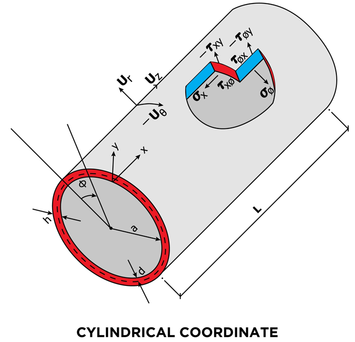 | Figure 1. Dimensions, Deformations and Stresses of the Cylindrical Shell |
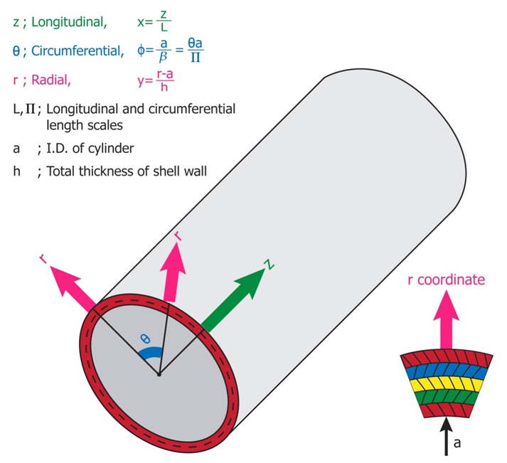 | Figure 2. Details of the Coordinate System |
2. Formulation of Cylindrical Shell Theory of Anisotropic Materials
Consider a non-homogeneous, anisotropic volume element of a cylindrical body with longitudinal, circumferential (angular) and radial coordinates being noted as z, θ, r, respectively, and subjected to all possible stresses and strains (Figure 1). Here, a is the inner radius, h the thickness and L the length. See Table 1.a : Inside Radius of Cylindrical Shellh : Total Thickness of the Shell Walld : Distance (thickness) from Inside rsiud to mechanical neutral surfaceSi : Radius of Each Layer of Wall (I = 1, 2, 3 -- - to the number of layer)L : Longitudinal Length Scale to be defined, Also Actual Length of the Cylindrical ShellΠ : Circumferential Length Scale of cylindrical shell to be definedEi : Young’s Moduli in I DirectionGij : Shear Moduli in i-j FaceSij : Compliance Matrix of Materials of Each Layerr : Radial CoordinateΠ : Circumferential Length Scale to be definedƔ : Angle of Fiber Orientationσ : Normal Stressesε : Normal Strainsz, θ, r : Generalized Coordinates in Longitudinal, Circumferential and Radial Directions Respectivelyτ : Shear Stressesεij : Shear Strains in i-j Faceλ ; Shell Thickness / Inside Radius (h/a)Cij : Elastic Moduli in GeneralX, φ, Y : Non Dimensional Coordinate System in Longitudinal, Circumferential and Radial Directions RespectivelyTable 1 List of SymbolsAssuming that the deformations are sufficiently small so that linear elasticity theory is valid, the following equations govern the problem: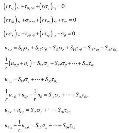 | (1) |
In the above Equations (1) are equilibrium equations and complete anisotropy of the material is allowed for and there are thus 21 independent material constants. We are not allowed to illiminate any of those components, since the material properties are dependent on the manufactures set up and different gravity environment in case of aerospace vehicles. Also the compliance matrix is symmetric, Sij is the same as Sji, and the components can be expressed in terms of engineering constants as follows: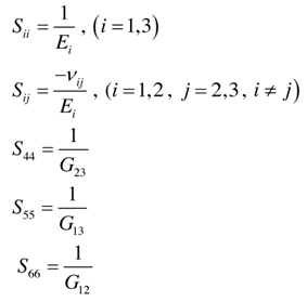 | (2) |
In equation (2) the Ei’s are the Young’s moduli in tension along the i – direction and Equation (2) implies anisotropic property of the material only, material to be non-homogeneous, different properties of each layer of the shell, we will allow the material property variation in the radial direction as follows: | (3) |
The above equation is unique and different from most of conventional theories, including Reddy’s, Reference (11), which input the engineering constants artificially from the beginning, while we take the existence and magnitude of components only by approximation theory of the asymptotic expansion.The principal material axes in general do not coincide with the body axes with respect to material axes specified, then the properties with respect to the body axes are given by the following transformation equations: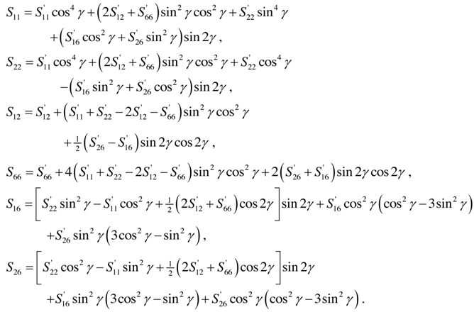 | (4) |
Where λ is the angle of anisotropic orientation between the original longitudinal coordinate z axes. The shell is subjected to a uniformly distributed tensile force, then the boundary conditions are as follows: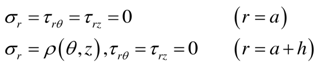 | (5) |
We will find it convenient to work with stress resultants rather than the stresses themselves. These stress resultants, which are forces and moments per unit length, are obtained by integrating with respect to the thickness coordinate. They are: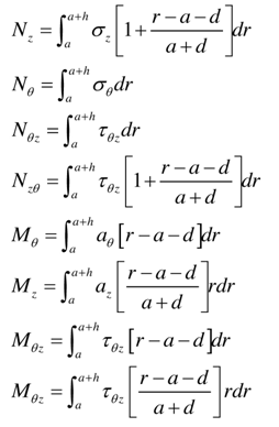 | (6) |
In the equations (6) variable, a, denotes the inner radius of the cylindrical shell and, d, the distance from the inner surface to the reference surface where the stress resultants are defined. 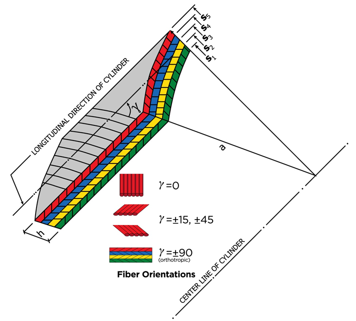 | Figure 3. A Laminated Cylindrical Shell, Material Orientation γ |
3. Formulation of a Boundary Layer Theory
As a first step to integrating equations (6), we make them non-dimensionalized coordinates as follows: | (7) |
are quantities which are to be determined later.The parameters L and Π are thus seen to be characteristic length scales for changes of the stresses and displacements in the axial and circumferential directions, respectively where λ is the thin shell parameter defined as | (8) |
The parameter λ is representative of the thinness of the cylindrical shell. The first system of equations of “thin shell” theory and we will call it the first approximation system. We can however obtain stresses and displacements of each layer of thickness coordinate, that can be an advantage of the procedure among others. In the following section, the thin shell theories for different combinations of length scales will be derived.
4. Formulation of Pure Membrane Theory
(Associated with characteristic length scales, a)As we observed, the shell geometry is an important factor for the formulation of theories.The basic geometry of cylindrical shells are the longitudinal length L, inside radius a, total wall thickness h and the distance from Inner surface to a desired surface, d. We are interested here in deriving the shell theory associated with the case where the axial and circumferential length scales are both equal to the inner radius of the cylinder, a, as follows: | (9) |
Here we adopt the concept of characteristic length scale first developed by Calladine in the Equation (9) in the Reference [15].The reason for taking the length scales, a, is the longest practical dimension of the shell and we are interested in developing membrane type theory which requires longer than the bending characteristic influential length according to the classical theory of isotropic materials.Substituting these length scales into the three-dimensional elasticity equations (1) and the asymptotic expansions the following equations representing the first approximation theory of the problem result upon use of the procedure outlined earlier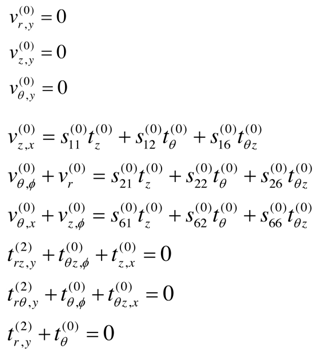 | (10) |
The superscripts indicate the leading term in each of the above equations and represent the relative of magnitude of the displacements and stresses. These orders of magnitude result from the intention to obtain a system of equations which is inferable with respect to the thickness coordinate y in a step-by-step manner with the following additional reasoning;a) The dominant stress state in thin shell theory is the in-plane stress state. These stresses should be of the same order of magnitude.b) The order of the displacements is chosen so that the product of the in-plane strains and the elastic moduli is of the same order of magnitude as the in-plane stresses.c) The choice for the transverse stresses arises from the fact that they should contribute terms of the same magnitude in the equilibrium. Integration of the first three equations of (10) with respect to y yields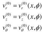 | (11) |
where , vr, vz, vӨ are the displacements in r, z and Ө directions respectively.The middle three equations of (10) can be solved for the in-plane stresses as follows: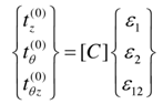 | (12) |
Here, C. (i, j = 1, 2, 3) are the components of a symmetric matrix given by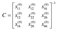 | (13) |
From equations (12) and (13) we can obtain strains as follows: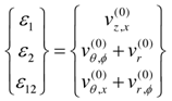 | (14) |
On substituting the first approximation in-plane stress-strain relations into the last three equations of (10) and integrating with respect to y, we obtain: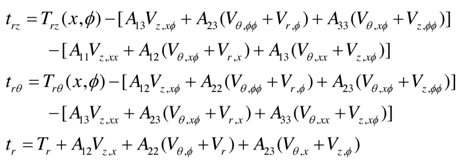 | (15) |
where Trz , TrӨ , Tr are the transverse stress components of the r =0 surface and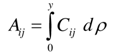 | (16) |
In relations (14) and in what is to follow, the superscripts on the displacements have been dropped.Boundary conditions are to be satisfied by each term of asymptotic expansions. This yields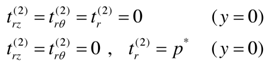 | (17) |
Here, p* is a dimensionless pressure defined by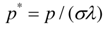 | (18) |
Satisfaction of conditions (17) by (15) yields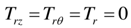 | (19) |
and the following three differential equations for displacements Vz, VӨ and Vr,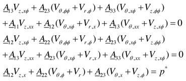 In the above equations
 | (20) |
To obtain the appropriate expressions for the stress resultants we first non-dimensionalize those defined by (9) as follows: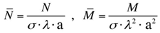 | (21) |
where N and M are the generic symbols for the force and moment stress resultants, respectively. Note that to non-dimensionalize the force and moment, we divide by same unit of force and moment per unit strip of the shell surface, which is of pound/inch or kilogram/centimeter for force and pound-inch/inch or kilogram-centimeter/centimeter respectively. Assuming it to be possible, we now asymptotically expand each of the dimensionless stress resultants in a power series in 1/2,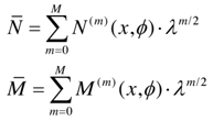 | (22) |
where N (m) and M (m) are of the order unity.
5. Pseudo-Membrane Phenomena
We are now interested in a formulation of equations to be able to obtain all the stress resultants due to membrane and bending actions.On substitution (21), (22) and the results for in-plane stresses (15) into relations (9) and equating terms of like powers in 1/2 on each side of the equations, we obtain the following expressions for the first approximation stress resultants: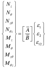 | (23) |
where the superscript zero has been omitted and B. is defined as follows: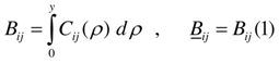 | (24) |
and submatrices [A] and [B] are given by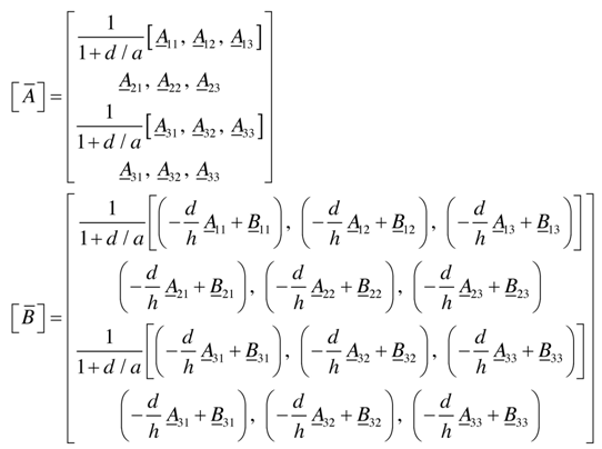 | (25) |
Note that d/a can be written as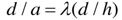 | (26) |
From the results obtained above, we characterize the theory as follows:a) The approach that this research took, the asymptotic integration, for deriving shell equations is capable of obtaining all stress components, including the transverse components.b) The first three equations of (9) result from the relations for the transverse strains. The variation with respect to y is zero, as shown in the displacements (23) which are independent of y. The strain components of any point y off r=0 surface are thus equal to those of they r=0 surface, similar to classical membrane theory.c) The stress components vary with y because as the y Cij, and the Aij are functions of  .d) Equations (23) show that moment stress resultants are produced due to the non-homogeneity of the material.For an isotropic and homogeneous material, Cij are constants and d/h = 1/2. This
 | (27) |
On substituting this result into relations (25), it is seen that submatrix B is equal to zero and that relations (27) become those of the classical membrane theory of shell (zero moment resultants). In the case of hybrid anisotropic materials, it is very rare to satisfy all the components of the submatrix [B] to be equal to zero at the same time. Another way of observation, it is unavoidable to associate with some bending moments in addition to pure membrane forces for laminated anisotropic shell walls, as clearly shown in Figure 5, the blue colored curves are the additional contribution to the pure membrane deformation. Therefore, the analysis is named pseudo-membrane theory. It is different from the long effective length of Vlasov’s semi membrane theory or the short effective length of Donnell’s theory, References [2, 6, 8 and 12].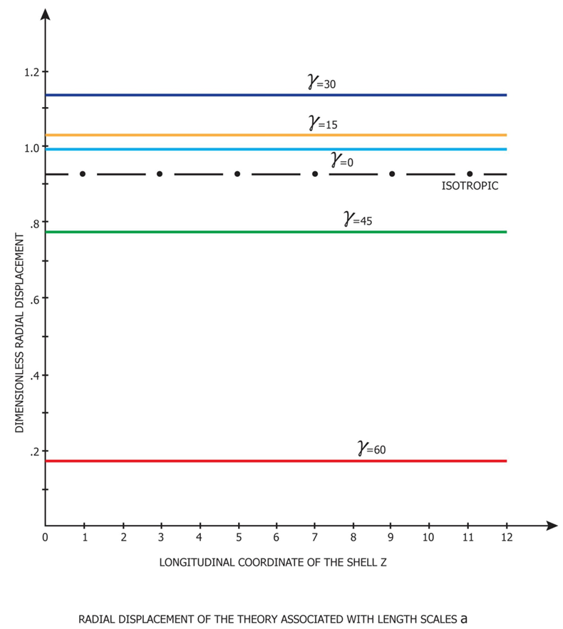 | Figure 4. Non-dimensionalized Radial Displacement of Pure Theory |
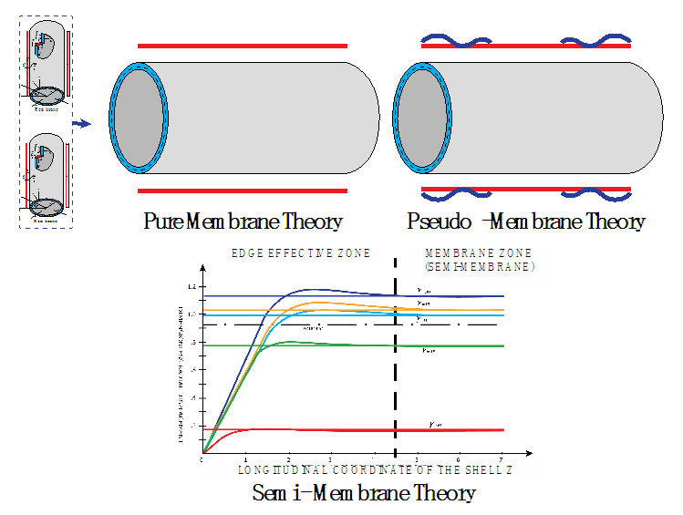 | Figure 5. Displacement of Semi-Membrane Theory |
6. Formulation of Semi-Membrane Theory
The cylindrical shell theory that we are concerned is among the three classifications of above is very long effective length shell which is well compared to Donnell-Vlasov theory. As shown in Figure 4, the edge effective zone due to the prescribed edge boundary condition represented by curved pattern is limited within close distance from the end and after the zone the deformation is nearly linear with respect to the longitudinal axis, which is very close to membrane analysis. It is more distinct for a cylindrical shell of one end fixed or hinged boundary condition and the other free open. That is semi-membrane status, we will now mathematically formulate the governing equations.According to Calladine, Vinson and Chung, References [15], [18], [19], [20] respectively, we pick and choose the longitudinal (L) and circumferential (Π) length scales as follows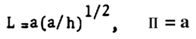 | (28) |
We can then obtain the following equations.Stress-displacement relations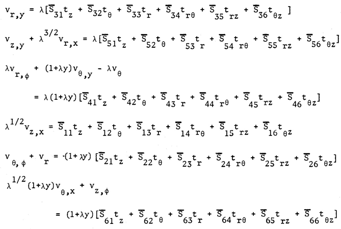 | (29) |
Equilibrium equations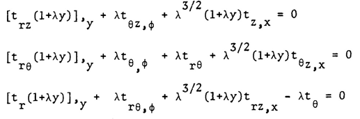 | (30) |
By going through the first approximation procedure of previous formulation as explained in the References [20], [21], [22], we found the following phenomena.Transverse Strains; the first three equations of (5) are zero and all displacements shown in (6) independent of thickness coordinate, r, which means it is only membrane state.In-plane Circumferential and Shear Strains; the longitudinal strain is represented by the combination of longitudinal and circumferential stresses (tz and tθ) In-plane Shear Stresses; trz does not appear in the first approximation theory.We now complete the second approximation theory of the asymptotic expansion and integration procedure, which can be shown as follows: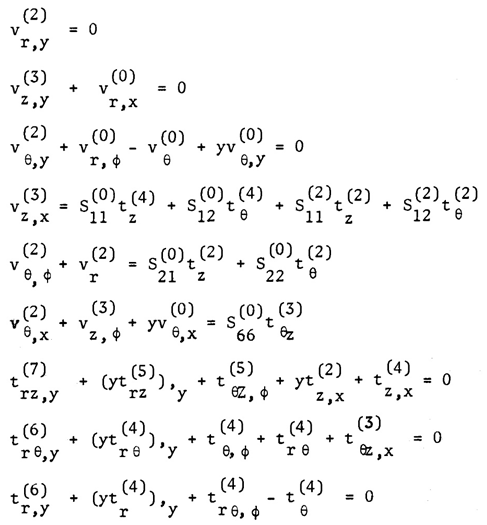 | (31) |
By integrating the first three equations of the above, we will obtain the following equations: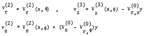 | (32) |
Insert the displacements obtained in the equation (5) into the middle three equations of (6) to obtain the following equations: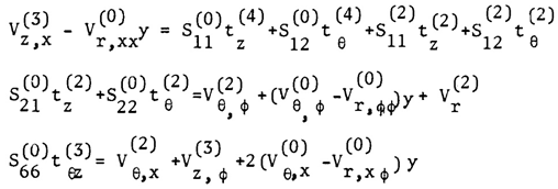 | (33) |
By combining the equation for Vz,x in the equation (6),we can obtain the in-plane stress-strain relations as follows: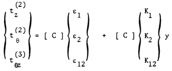 | (34) |
where 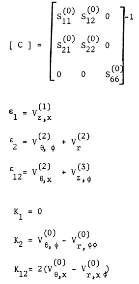 | (35) |
Substituting tz, tθ and tθz into the first approximation equations of (5), we will obtain the following transverse stresses: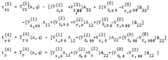 | (36) |
After mathematical manipulation and inserting boundary conditions, we can obtain the following final equations: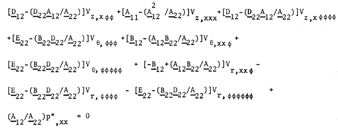 | (37) |
where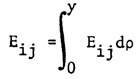 | (38) |
The above differential equations are the governing equations of semi-membrane theory.
7. Application
We choose a problem of a laminated circular cylindrical shell under internal pressure and edge loadings to demonstrate the validity of the theories developed here. The shell is assumed to build with boron/epoxy composite layers. Each layer is taken to be taken to be homogeneous but anisotropic with an arbitrary orientation of the elastic axes. We need not consider the restriction of the symmetry of the layering due to the non-homogeneity considered in the original development of the theory expressed earlier. Thus each layer can possess a different thickness and a different material.We assume here that the contact between layers is such that the strains are continuous function in thickness coordinate. As the  are piecewise continuous functions, the in-plane stresses are also continuous. We would expect them to be discontinuous at the juncture of layers of dissimilar materials. The transverse stresses are continuous functions of the thickness coordinate, r. Although as mentioned above the theory developed can take unlimited hybrid random layers but for an example, a four-layer symmetric angle ply configuration. For this configuration the angle of elastic axes
  is oriented at
  ,
,  ,
,  ,
,  with the shell axis and the layers are of equal thickness.Let the shell be subjected to an internal pressure
  , an axial force per unit circumferential length
  . The axial force is taken to be applied at
  such that a moment
  is produced about the reference surface
  . We introduce dimensionless external force and moments as described earlier.To demonstrate the validity of the derived theory, we have simplified loading and boundary conditions as:
 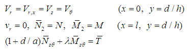 | (39) |
Here,  is the dimensionless length of the cylindrical shell.The distance d at which the stress resultants were defined was left arbitrary. We now choose it to be such that there exists no coupling between
  and
and  and
and  and
and  .As the loading applied at the end of the shell is axi-symmetric, all the stresses and strains are also taken to be axi-symmetric. We thus can set all the derivatives in the expressions for the stresses and strains and in the equations for the displacements equal to zero.Numerical calculations are now carried out for a shell of wall of various hybrid laminae.Each of the layers is taken to be equal thickness and thus the dimensionless distances from the bottom of the first layer are given by
 each layer of the symmetric angle ply configuration (elastic symmetry axes y are oriented at
 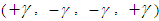 is taken to be orthotropic with engineering elastic coefficients representing those for a boron/epoxy material system,
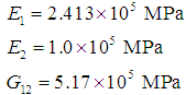 Here direction 1 signifies the direction parallel to the fibers while 2 is the transverse direction. Angles chosen were
  =0, 15, 30, 45 and 60. Use of the transformation equations of Equation (4) of this article then yields the mechanical properties for the different symmetric angle ply configurations.We next apply the following edge loads:
  and take
  ,
,  and the reference surface we take
  . Due to the simplicity we took the loading was internal pressure and therefore we were allowed the governing equations (15), (20), (28) and (37) as axi-symmetric deformations and the variables differentiated with respect to the angular coordinate, φ, were allowed to be equal to zero. Then we will find the simplified version of the above equations are identical.Shown in Figures (4) and (5) are the variation of the dimensionless radial displacement with the actual distance along the axis for the different theories. The reference surface for the chosen configuration is given by
  . The integration constants determined from the edge conditions. For the behavior of deformations, stresses and strains we can classify two apparently different patters asAxi-symmetricAxi-asymmetricAxi-symmetric patterns are as shown in Figures (4) and (5). Axi-asymmetric patters with respect to longitudinal axis, x, for the case of compressive loads are identical as column behavior which will lead to Eigenvalue problem mathematically.It is also seen that wide variations in the magnitude of radial displacement take place with change in the cross-ply angle. The maximum displacement occurs at
  = 30 degree while the minimum displacement is at
  = 60 degree. Also shown in the Figure 5 is the patterns of near edge zone for both bending theories, one is simplified bending theory shown in the Figures(4) and (5) the other the expanded Donnell Vlasov bending theory for hybrid anisotropic materials. The results of both bending theories are identical for the case of internal pressure loading as explained earlier. It is interesting to observe the non-linear deformation in the Figure (4) and (5) due to the prescribed edge boundary conditions last only very short length in longitudinal direction, which we call effective bending zone, after the zone it is more of linear membrane deformations are governing. In Reference [13], “Pseudo Membrane Shell Theory of Hybrid Anisotropic Materials”, explains more mathematically.In each case, the displacements increase with increase in
  up to
up to  =30 degree and thereafter decrease. As shown in Figure (4), recommended use of original theory, Equation (10), and simplified version, Equations (19) and (20), are classified.
8. Conclusions
First approximation shell theories are derived by use of the method of asymptotic integration of the exact three-dimensional elasticity equations for a non-homogeneous anisotropic circular cylindrical shell. The analysis is valid for materials which are non-homogeneous to the extent that their properties are allowed to vary with the thickness coordinate (r).The first approximation theory derived in this analysis represents the simplest possible shell theories for the corresponding length scales considered. Although twenty one elastic coefficients are present in the original formulation of the problem, only six appear in the first approximation theories. Depending on the length scales, longitudinal and circumferential, we obtain the governing equations and explain the particular behavior of each theory.For pure-membrane theory, we used both longitudinal and circumferential length scales same as internal radius of the shell. Pseudo-membrane theory is simply a by-product of laminated wall thickness of different anisotropic materials, that is, the difference between geometric half thicknesses and the true mechanical neutral axis.In the case of semi-membrane theory, we used the longest possible longitudinal length scale together with normal circumferential length scale which is inner radius of the shell. Because of the longest longitudinal length scale, the boundary conditions of the other end of the cylindrical shell become meaningless, that is the particular behavior of semi-membrane theory.Semi-membrane shell theory is very useful for long cylindrical shells, such as long rocket fuel storage tank and long airplane fuselage structures.
ACKNOWLEDGEMENTS
The research was sponsored by Summit Partners in Menlo Park, California, USA, and is graciously acknowledged.
References
| [1] | Love, A.E.H, “A treatise on the mathematical theory of elasticity”, Dover Edition, New York. |
| [2] | Donnell, L.H., “Beams, Plates and Shells”, McGraw-Hill Book Company, ISBN0-07-017593. |
| [3] | Reissner, E., “The effect of transverse shear deformation on the bending of elastic plates”, J. Appl. Mech.12, No A69-77, 1945. |
| [4] | Johnson, M.W. and Widera, O.E., “An asymptotic dynamic theory for cylindrical shells”, Studies Appl. Math. 48,205, 1969. |
| [5] | WIDERA, O. E., “An asymptotic theory for the motion of elastic plates”, Acta Mechanica 9, 54, 1970. |
| [6] | Vlasov, V.Z., “General theory of shells and its application in engineering”, NASA TT F-99, National Tech. Information Service. |
| [7] | Vlasov, V.S., “Basic Differential Equations in General Theory of Elastic Shells”, NACA Technical Memorandum 1241, 1951. |
| [8] | Goldenveiser, A.L., “Theory of elastic thin shells”, Pergamon Press. |
| [9] | Ting, T.C.T., “Anisotropic Elasticity”, Oxford Engineering Science Series 45, Oxford University Press. |
| [10] | Birman, V., “Extension of Vlasov’s Semi-Membrane Theory to Reinforced Composite Shells”, J. Appl Mech 59 (2), 464-464. |
| [11] | Reddy, J.N., “Mechanics of Laminated Composite Plates and Shells”, 2nd Edition, CRC Press. |
| [12] | ASME Boiler Code - Boiler & Pressure Vessel Code, 2015. |
| [13] | ACI 318-11: Building Code Requirements for Structural Concrete and Commentary. |
| [14] | Blaauwendraad, J and Hoefakker, J.H., “Structural Shell Analysis’, Springer, ISBN 978-94-007-6700-3. |
| [15] | Calladine, C.R., “Theory of Shell Structures”, ISBN 0 521 23835 8, Cambridge University Press. |
| [16] | Ambartsumian, S.A., “Fragments of the Theory of Anisotropic Shells”, World Scientific Publishing Co., ISSN 0218-0235. |
| [17] | Chung, S.W., Hong, S.G., Mendenhall, D.A., “Compare and Contrast Bending Shell Theories of Hybrid Anisotropic Materials”, International Journal of Composite Materials, p-ISSN: 2166-479X e-ISSN: 2166-49192017; 7(1): 8-19. |
| [18] | Chung, S.W. and Park, S.M., “A Shell Theory of Hybrid Anisotropic Materials”, International Journal of Composite Materials, Volume 6, Number1, February 2016. |
| [19] | Chung, S.W. and Hong, S.G., “Pseudo Membrane Shell Theory of Hybrid Anisotropic Materials”, Journal of Composite Structures, Volume 160, Number1, January 2017. |
| [20] | Chung, S.W. and Ju, G.S., “SEMI-MEMBRANE SHELL THEORY OF HYBRID ANISOTROPIC MATERIALS”, European Journal of Engineering and Technology, Vol. 5 No.2, 2017, ISSN2056-5860. |
| [21] | Chung, S.W. and Ju, G.S., “Semi-Membrane and Effective Length Theory of Hybrid Anisotropic Materialas”, International Journal of Composite Materials 2018, 7(3):103-114, DOI:10.5923/j:cmaterials 20170703.03. |
| [22] | Tonabene, F and Fantuzzi, N, “Mechanics of Laminated Composite Doubly-Curved Shell Structures” ISBN 978-88-687-6. |

 Abstract
 Reference
 Full-Text PDF
 Full-text HTML