-
Paper Information
- Paper Submission
-
Journal Information
- About This Journal
- Editorial Board
- Current Issue
- Archive
- Author Guidelines
- Contact Us
International Journal of Composite Materials
p-ISSN: 2166-479X e-ISSN: 2166-4919
2018; 8(3): 64-71
doi:10.5923/j.cmaterials.20180803.03

Effect of Fiber Orientation on Shear Behavior of RC Beams Externally Strengthened with CFRP
 Abstract
 Reference
 Full-Text PDF
 Full-text HTML
Mohamed H. Arafa, Mamoun A. Alqedra, Mohammed Hammad
Department of Civil Engineering, The Islamic University of Gaza, Gaza, Palestine
Correspondence to: Mohamed H. Arafa, Department of Civil Engineering, The Islamic University of Gaza, Gaza, Palestine.
| Email: |  |
Copyright © 2018 The Author(s). Published by Scientific & Academic Publishing.
This work is licensed under the Creative Commons Attribution International License (CC BY).
http://creativecommons.org/licenses/by/4.0/

Strengthening of reinforced concrete beams with carbon fiber reinforced polymer (CFRP) is one of the recent applied strengthening techniques. It offers an attractive solution to enhance shear and flexural capacities of reinforced concrete (RC) beams. Behavior in shear and flexure of reinforced concrete beams externally strengthened with CFRP is highly influenced by the way in which these composites are bonded to the beam. In this paper reinforced concrete (RC) beams strengthened with CFRP was modelled using a nonlinear finite element (FE) model to study the influence of the orientation layer of CFRP on the overall response of strengthened RC beams in shear. This is carried out to achieve the optimum utilization of such strengthening technique in terms of load bearing capacity and possible deflection values. A nonlinear finite element software ANSYS was utilized in this study. The analysis of the results indicated that the overall behavior of the FE models have a good agreement with corresponding previous experimental results. Further, the parametric study proved that shear strengthening of RC beams with vertical CFRP fabric is more efficient than strengthening with CFRP fabric inclined at an angle of 45°. Furthermore, strengthening the reinforced concrete beams with one layer of U-wrap CFRP fabric inclined at an angle of 45° with an additional horizontal layer of CFRP fabric on both sides of the web is more efficient than strengthening with one layer of U-wrap vertical CFRP fabric with an additional horizontal layer of CFRP fabric on both sides of the web.
Keywords: Carbon fiber, Strengthening, Reinforced concrete, Finite element, Modelling
Cite this paper: Mohamed H. Arafa, Mamoun A. Alqedra, Mohammed Hammad, Effect of Fiber Orientation on Shear Behavior of RC Beams Externally Strengthened with CFRP, International Journal of Composite Materials, Vol. 8 No. 3, 2018, pp. 64-71. doi: 10.5923/j.cmaterials.20180803.03.
Article Outline
1. Introduction
- The use of fiber reinforced polymer (FRP) as a strengthening material is one of the applied strengthening techniques of reinforced concrete beams. This results from a number of advantages, such as excellent strength to self-weight ratio, high tensile strength, large fatigue resistance capacity, and high durability, [1] and [2]. Reinforced concrete (RC) beams strengthened with carbon and glass fiber-reinforced polymer (CFRP and GFRP) composites introduces a promising solution to improve shear and flexural capacities and ductility, as well as altering the mode of rupture, [3-6].Obtaining the behavior of FRP strengthening reinforced concrete structures has become a very significant research field. Experimental wise, several studies were carried out to investigate the behavior of strengthened beams and the influence of various parameters, [7-11]. Despite the fact that performing laboratory experiments are extremely useful in obtaining the composite behavior of FRP and reinforced concrete, developing validated and verified numerical models would assist establishing a good understanding of the behavior at lower costs in terms of time and money, [12-15]. In this research, non-linear finite element analysis models using ANSYS [16] software for strengthening reinforced concrete beams with carbon fiber reinforced polymers (CFRP) is presented. Moreover the validated and verified finite element model was applied to study the influence of CFRP layer inclination on the overall response of strengthened RC beams in shear.
2. FE Modelling of Strengthening of RC Beams with CFRP
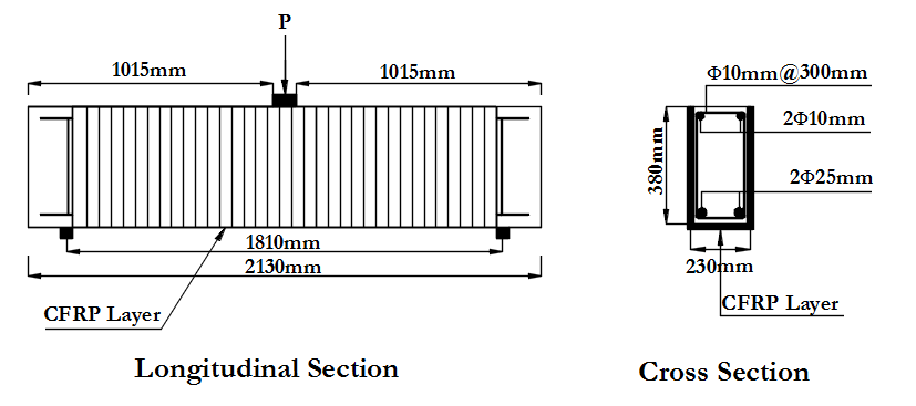
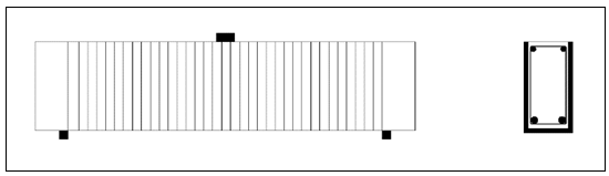
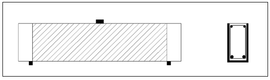
- The experimental investigation of [17] was applied to verify the developed FE model for strengthening RC beams in shear with CFRP using ANSYS software. The control beam is a simply supported RC beam with a total length of 2130 mm, and a clear span of 1830 mm. The beam has a rectangular cross section with 230 mm width and 280 mm height, and a concrete cover of 25 mm was assumed. The beam was subjected to a concentrated static load at the middle of the beam. Tension reinforcement of the beam is 2Ø25 mm. Compression reinforcement of the beam is 2Ø10 mm. And shear reinforcement of the beam is 10 mm diameter stirrups spaced at 300 mm, as shown in Figure (1).
 | Figure (1). Shear Control Beam Model, [17] |
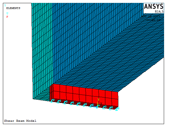
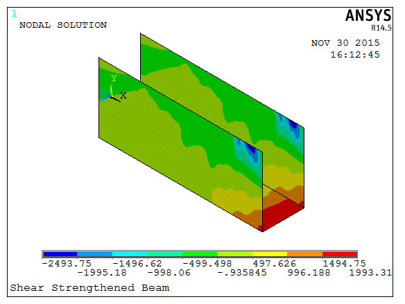
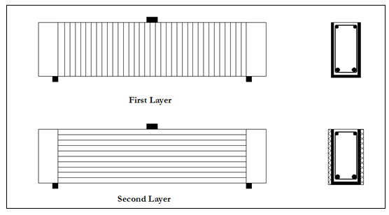
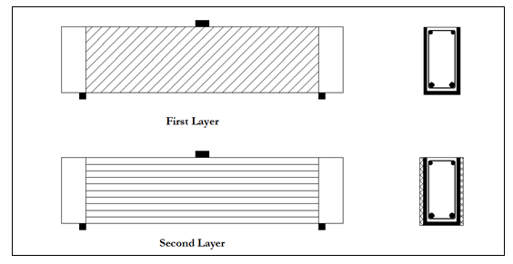
 | Figure (2). Shear Strengthened Beam Model, [17] |
2.1. Element Types
- Several elements have been applied to simulate the behavior of CFRP-strengthened reinforced concrete beam. These elements are widely used in ANSYS and recommended by previous researchers, [1, 8, 9, 12, 14, 19-21].For reinforced concrete, an eight-node solid element, Solid 65, was considered to simulate the concrete. The solid 65 element has eight nodes with three degrees of freedom at each node: translations in the nodal local x, y, and z directions. The element is capable of carrying plastic deformation, cracking in three orthogonal directions, and crushing.Link 180 element was utilized to model steel reinforcement. The element is a uniaxial tension-compression element with three degrees of freedom at each node: translations in the nodal x, y, and z directions. Plasticity, creep, rotation, large deflection, and large strain capabilities are included. Homogeneous structural solid with simplified enhanced strain formulation Solid 185 is used to model loading and supporting steel plates. This element is also defined by eight nodes having three degrees of freedom at each node. The element is capable of plasticity, hyper elasticity, stress stiffening, creep, large deflection, and large strain capabilities.Shell 181 element is also applied to model Carbon Fiber Reinforced Polymer (CFRP). It is a four-node element with six degrees of freedom at each node.
2.2. Materials Models
- Hognestad model [22], has been used to simulate the stress-strain behavior of concrete. This model is also adopted in the work of [23] and [7]. In this research, the tri-axial behavior of concrete is modelled according to the constitutive model of [24].To ensure the full connectivity between concrete and steel reinforcement nodes, discrete steel model was used. An elastic-plastic constitutive relationship with strain hardening is assumed for reinforcing steel. This model generally yields acceptable results for the response prediction of RC members, [14, 25, 26]. CFRP composites is modeled using the orthotropic linear elastic model, [2] and [27]. The properties of the CFRP composites were considered the same in any direction perpendicular to the fibers. This means that the properties in the y direction were similar to that in the z direction. The Maximum strain failure criterion and maximum stress failure criterion were used, based on the longitudinal tensile strength and maximum strain of CFRP fabrics.
2.3. Beam Geometry and Meshing
- The advantage of the symmetry of the beams allows modelling a half of full beam size. This resulted in significantly reducing the computational time and computer disk space requirements. Since half of the beam is to be modeled, the beam model is 1065 mm long, with a cross-section of 230 mm × 380 mm. The CFRP fabric layer bonded to the beam soffit and sides as U-wrap was modeled as three areas. The advantage of symmetry allows simulating half of loading plate and one support plate. The steel loading and supporting plates are 30 mm x 50 mm x 230. To obtain good results from the Solid 65 element, a rectangular mesh is recommended by [28] and [3]. Therefore, the mesh is set up such that square or rectangular elements are to be created. Steel loading and supporting plates were meshed as solid elements in such a way that its nodes were oriented with adjacent concrete solid elements. As mentioned earlier, perfect bond between materials was assumed. The modelling of perfect bond was done by linking the nodes of the steel reinforcement element with those of the adjacent concrete solid element. Sharing the same nodes ensures that both materials creates such perfect bond between them, [28] and [3]. Figure (3) illustrates the reinforcement configuration modeled in ANSYS for beam model.
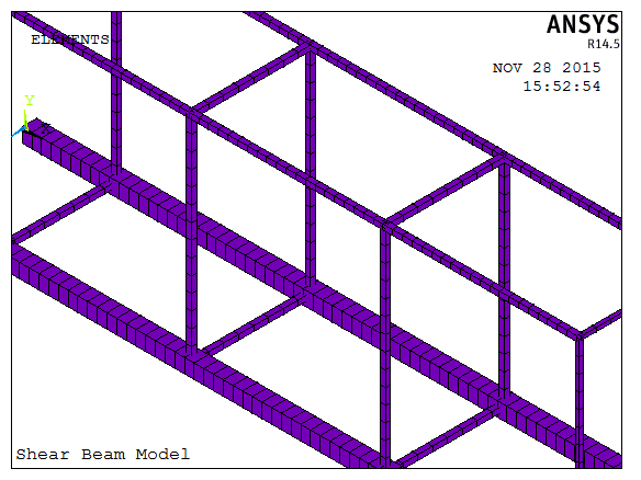 | Figure (3). Reinforcement Configuration |
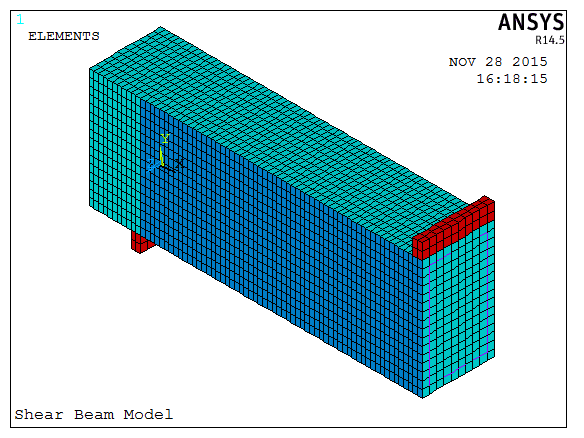 | Figure (4). Overall Meshing of the Model |
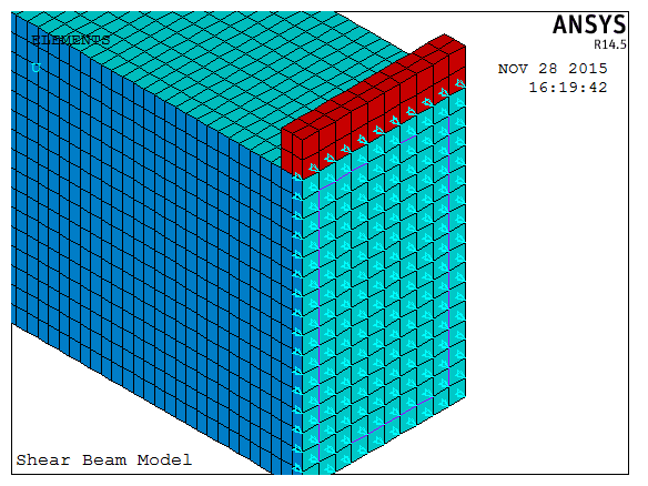 | Figure (5). Plane of Symmetry |
 | Figure (6). Beam Support Plate |
2.4. Finite Element Model Verification
- The load-deflection curve obtained from the finite element analysis agrees well with that of the experimental results for the same strengthened beam, as indicated in Figure (7). In the linear range, the finite element analysis indicated that load-deflection behavior is stiffer than that of the experimental results. The first cracking load of the finite element analysis is 50 kN. Beyond that, the finite element model indicated stiffer values than that of the experimental beam. The bottom steel reinforcement of the finite element beam model yields at 350 kN. The ultimate load of 410 kN from the finite element beam model is lower than the average ultimate load of 421 kN obtained from the experimental beam; this indicates a difference of 2.6%. The load-deflection behavior obtained from the finite element models for control and strengthened beams is shown in Figure (8).
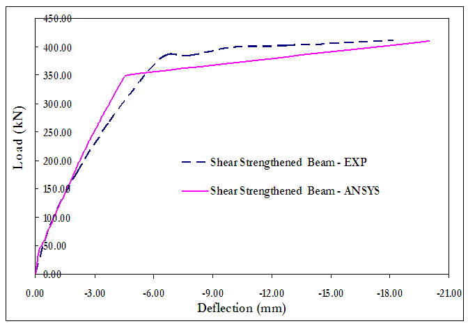 | Figure (7). Load deflection curves of experimental and FE model of strengthened beam |
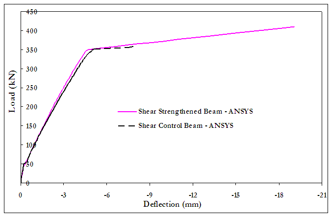 | Figure (8). Load deflection curves of FE Model for control and strengthened beam |
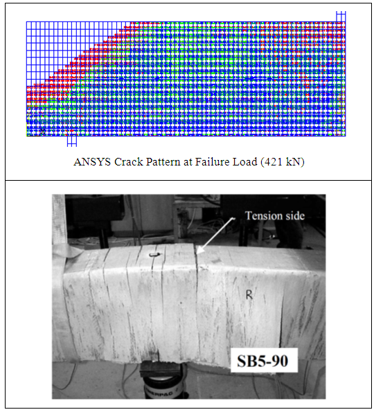 | Figure (9). Cracks Propagation – Strengthened Beam at Failure Load (421 kN) |
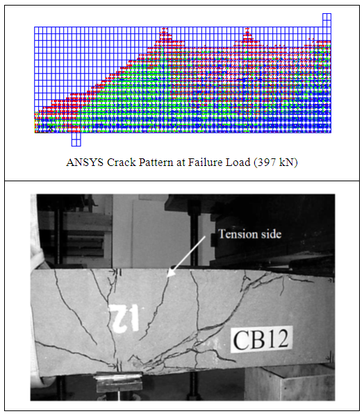 | Figure (10). Cracks Propagation– Control Beam at Failure Load (397 kN) |
 | Figure (11). Stress of CFRP Fabric at Failure –Strengthened Beam |
3. Effect of CFRP Orientation on the Shear Strength
- To evaluate the effect of CFRP orientation with the longitudinal axis of the beam on the shear strength of the beam, four strengthening configurations were tested using the verified FE beam model:1- Configuration A: one layer of vertical U-wrap CFRP, Figure (12).2- Configuration B: one layer of vertical U-wrap CFRP and an additional horizontal layer of CFRP fabric on both sides of the web, Figure (13).3- Configuration C: one layer of U-wrap CFRP fabric, inclined at an angle of 45° to the longitudinal axis of the beam, Figure (14).4- Configuration D: one layer of U-wrap CFRP fabric inclined at an angle of 45° and an additional horizontal layer of CFRP fabric on both sides of the web, Figure (15).
 | Figure (12). Configuration A |
 | Figure (13). Configuration B |
 | Figure (14). Configuration C |
 | Figure (15). Configuration D |
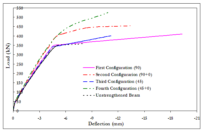 | Figure (16). Effect of CFRP Inclination – Load Deflection Curves |
|
4. Conclusions
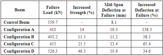
- The important conclusions drawn from the study are listed below:1. Finite element model was successfully verified as compared with previously experimental test results. Therefore, ANSYS can be confidently used in analysis of RC beams externally strengthened with Carbon Fiber Reinforced Polymers (CFRP) fabrics.2. The overall behavior of the finite element models represented by the load-deflection curves at mid-span shows acceptable agreement with the experimental data obtained from full-scale beam tests. However, the finite element models show slightly differed stiffness values as compared with the experimental data. The effects of bond slip between the concrete and steel reinforcing and micro-cracks occurring in the actual beams were excluded in the finite element models, contributing to the difference in stiffness of the finite element models.3. Strengthening the RC beam by bonding a single vertical layer of U-wrap CFRP fabric, increases the shear strength of the beam by 14%, and increases the mid-span deflection at failure by 138%.4. Strengthening the RC beam by bonding a single layer of U-wrap CFRP fabric, inclined at an angle of 45° to the longitudinal axis of the beam increases the shear strength of the beam by 11.5%, and increases the mid-span deflection at failure by 38%.5. Shear strengthening of RC beams with one vertical layer of CFRP fabric is more efficient than strengthening with one layer of CFRP fabric inclined at an angle of 45°.6. Strengthening of RC beams with one vertical layer of U-wrap CFRP fabric with an additional horizontal layer of CFRP fabric on both sides of the web increases the shear strength of the beam by 25.5% and increases the beam mid-span deflection by 65%. 7. Strengthening of RC beams with one layer of U-wrap CFRP fabric inclined at an angle of 45° with an additional horizontal layer of CFRP fabric on both sides of the web increases the shear strength of the beam by 46.3% and increases the beam mid-span deflection by 34.6%.8. Strengthening of RC beams with one layer of U-wrap CFRP fabric inclined at an angle of 45° with an additional horizontal layer of CFRP fabric on both sides of the web is more efficient than strengthening with one vertical layer of U-wrap CFRP fabric with an additional horizontal layer of CFRP fabric on both sides of the web.