-
Paper Information
- Paper Submission
-
Journal Information
- About This Journal
- Editorial Board
- Current Issue
- Archive
- Author Guidelines
- Contact Us
International Journal of Composite Materials
p-ISSN: 2166-479X e-ISSN: 2166-4919
2018; 8(1): 1-9
doi:10.5923/j.cmaterials.20180801.01

An Experimental Study on Impact of Cyclic Damage on Residual Flexure Strength of Plain Weave Carbon/Epoxy Composite
 Abstract
 Reference
 Full-Text PDF
 Full-text HTML
1Department of Aeronautical Engineering, MLR Institute of Technology, Hyderabad, India
2KIIT University, Bhubaneswar, Odisha, India
Correspondence to: P. K. Dash, Department of Aeronautical Engineering, MLR Institute of Technology, Hyderabad, India.
| Email: |  |
Copyright © 2018 Scientific & Academic Publishing. All Rights Reserved.
This work is licensed under the Creative Commons Attribution International License (CC BY).
http://creativecommons.org/licenses/by/4.0/

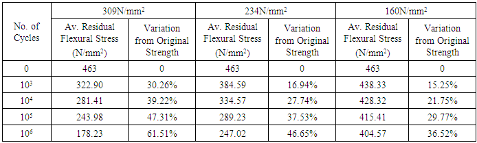
The growing use of plane-weave carbon fibre reinforced composite in aerospace components design demanded to support and define the engineering concepts of durability and damage tolerance. After fatigue damage, the reliability information in terms of flexure strength investigated in this paper. A series of three point flexure tests conducted over the range of cyclic damaged specimens. The experimental results analysed with reference to residue strength and reduced stiffness of the CFRC specimens. Fatigue damage followed by flexure tests produced significant strength reduction in comparison to simple flexure tests, and the reduction in residual flexural strengths and stiffness purely depended on the magnitude of fatigue stress applied with number of cycles subjected to bi-directional woven carbon/epoxy composite specimens.
Keywords: CFRC, Cyclic Damage, Flexure Test, Residual Strength, Residual Stiffness
Cite this paper: P. K. Dash, Ankita Dash, An Experimental Study on Impact of Cyclic Damage on Residual Flexure Strength of Plain Weave Carbon/Epoxy Composite, International Journal of Composite Materials, Vol. 8 No. 1, 2018, pp. 1-9. doi: 10.5923/j.cmaterials.20180801.01.
Article Outline
1. Introduction
- Structural components made of carbon fiber reinforced composite shown significant potential in wide variety of structural applications such as in aircraft and aerospace industry, automobile industry, sporting goods, offshore structures, and civil engineering [1]. This composite material possess attractive properties like, the high strength to weight ratio and high stiffness to weight ratio, excellent fatigue strength, ease of formability, wide range of operating temperatures (thermoplastic resins and carbon-carbon composites), negative or low coefficient of thermal expansion, high damping, resistance to corrosion, and flexibility for being tailored according to requirements [2, 4, 6]. Instead of all these virtues, the safety, reliability and durability of this material are directly depends on material responses under a number of controlled conditions or what is more commonly called as fatigue and post-fatigue behavior and can avoid the unseen challenges of this composite material [3, 5, 7, 8]. For example, the relationship between damage modes, failures modes and the state of microstructure of composites define the manner in which composite could be designed for a long-term service and under external influences such as mechanical, thermal, chemical and catastrophic loading. Also, the changes shall be correlated on the line of certain rational approach, so that fundamental questions like safe life of the component will be determined in fairly general circumstances [2]. In concise, it is desired to predict the residual strength and stiffness as a function of material life and loss of mechanical strength of this newly immerged material, before using it in full scale.Understanding, fatigue degradation of material is critical to ensure the long-term reliability of a components and structures. The evaluation of residual strength of in-service parts is important to ensure structural integrity (catastrophic failure does not occur). The residual strength and stiffness test allows the evaluation of remaining strength and stiffness in a structure after a given life cycle. Reviews of previous researches revealed that the fatigue failure could be defined in terms of material strength
 , material stiffness and material modulus [1-31]. As the fatigue cycle increased with constant loading, the fatigue life also reduced sizably. It is required to investigate the percentage of degradation of material strength with respect to fatigue stress and dynamic cycles. There is several method of observation and modeling the degradation, and it is quite complex in case of composite. As composites have flexibility to tailor made into required orientation, and lamination, so complexity of various failure mode varies on different types of fabrication, material inclusion and method of fabrication. Research related to monitoring the residual strength degradation through experiments, modelling, and statistically scaling of fatigue damage and successive effect over the material reported earlier under different loading environment [1]. Also, the research related to environmental effect on fatigue of composites and strength degradation are well documented. Poursartip et al (1986) reported the damage mechanism of carbon fiber composite both experimentally and theoretically. The residual strength of multi-directional carbon fiber laminated composite has been investigated by Rotem (1988). Beamount (1990) studied the static and cyclic loading and the effect of environment on accumulation of damage in composite laminates. Eggers et al (1991) studied the characteristic damage state in cross ply laminates of carbon fiber reinforced epoxy under varied stacking sequence, tensile fatigue loading and thermal cycling. The prediction of fatigue life and evaluation of fatigue damage for composite laminates has been investigated by Liu and Lessard (1994). The remaining strength and life of composite materials with time and cycle dependent degradation process was analyzed by Reifsnider and Xu (1995). Kawai et al (1996) studied the influence of matrix durability on progressive damage during fatigue loading on carbon fiber plain woven roving fabric laminate. Hwang and Han (1989) presented a theoretical modeling on fatigue damage and life prediction of composite. Agrawal and Joneja (1982) studied strain controlled flexural fatigue of unidirectional oriented reinforced glass fiber epoxy composite. Ozaki et al. (2015) reported the residual flexural strength after impact damage of textile made carbon fiber reinforced composite. Im et al. (1998) studied the static and fatigue bending strengths of CFRP laminates having impact damages via foreign object.In this paper, the residual flexural strength and stiffness of woven carbon fiber reinforced composite with constant volume fraction and constant thickness is determined after different cycles of fatigue damage at various stress cycles. The observed results are presented in form of cumulative damage degradation rate.
2. Experimental Procedure
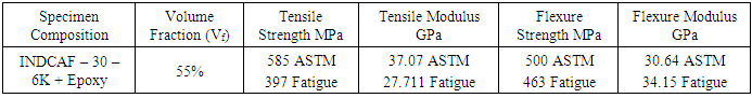
- i) Materials and specimens: A plane-weave carbon fiber cloth with epoxy resin used as materials for the current test program. The fibers INDCARF–30 type with 3K-filament count, a product of IPCL, and a non-hygroscopic epoxy resin matrix (Araldite – LY5052 and a hardener – HY5052), a Ciba-Geigy product were used for specimens fabrication. The laminates were laid-up as an 8-ply in the form of ()8 and were autoclave processed using a classical 180°C epoxy cure cycle. The so-cured laminates were about 1.68mm thick, and had a nominal 55% fiber volume fraction. After fabrication, the laminated plates were scanned using an ultrasonic probe immersed in water to assess their quality and to determine areas of potential weakness.A microphotograph of specimen’s cross section with fiber distribution is shown in photograph (a). The laminates were then cut using a diamond-tipped slitting wheel into individual specimens measuring as 90Χ25Χ1.68mm as per ASTM STD D790 for three point flexure testing (fig.1) and 90Χ30Χ1.68mm for fatigue testing as specific to the machine (fig. 2).ii) Flexure testing: Three point bending flexure tests were carried out under a UTM and as per ASTM D 790M standard. The dimension of ASTM specimen is shown in fig. 1. A pair of dial gauge is used to monitor the deflection at the bending point. The flexure modulus has been determined from the slope of load vs. deflection diagram, and presented in Table-1.
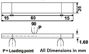 | Figure 1. Dimensions of flexure test specimens for 3-point bending method |
|
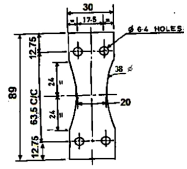 | Figure 2. Dimensions of Fatigue Test Specimens (All dimensions are in mm.) |
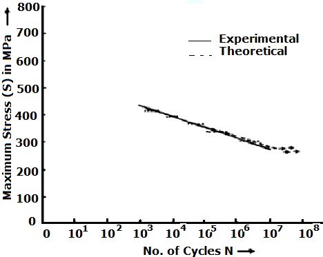 | Figure 3. S-N Diagram of bidirectional Woven Carbon/Epoxy Composite |
|
|
3. Results and Discussion
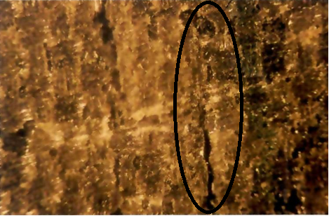
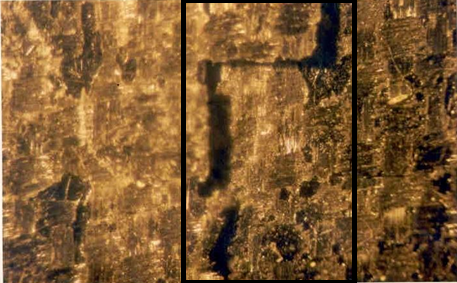
- Experimental observations are analyzed on the following paragraph quoting suitable tables, photographs and figures. i) Flexure strength:The flexure strength found out through three-point bending flexure tests for standard ASTM specimens (fig.1.a) and for fatigue specimen (fig.1.b). It has been observed that there are 7% variation in their results (Table-1). Likewise, the flexure modulus determined from load deflection curve during the three point bending tests had shown 11% variation when compared. The average results of six specimens for flexure strength and flexure modulus are presented in table-2.As the failure of a flexure loaded composite specimen depends on the type of fiber alignment to load and thickness of the specimen, the flexure load transferred to the horizontal aligned fibers produced moment and failed in any of the mode, i.e., tension, compression, or shear. Also, the combination of these modes has been resulted in certain cases. Failure is initiated, when any of these three stresses has reached its corresponding limit. If flexure stress is equal to shear stress, then flexure strength is same as inter laminar shear strength, and again if flexure stress is greater than longitudinal tensile or compressive strength, one of the highly stressed outer plies has failed due to matrix deformation. Horizontal shear failure in terms of splitting has the main feature in majority specimens as found in present study. Also, the wrinkling of the compression surface near the load nose and permanent shear deformation is marked. Including to above causes, another difference for fatigue specimen is that it has less area at flexure loading point, and has reduced strength due to stress concentration effect.ii) Fatigue strength:Rotational bending fatigue tests at different bending moment were carried out to determine fatigue life of carbon fiber reinforced composite specimens and shown in fig. 3 in form of S-N graph. The fatigue lives of the tested specimens were distributed in between 70% to 55% of tensile strength and at the cyclic range of 103 to 107 cycles. The photograph ‘b’, ‘c’ and ‘d’ have shown the type of failure of the specimens at different stress labels and at different number of cycles. As the composite have several modes of failure, like crazing, debonding, delamination, thermal residual stress effects, and crack propagation, it is possible to occur all in any combination in the fatigue process.In addition, the peak stress was high enough to precipitate large numbers of fiber failures within the material at high fatigue stress and caused a progressive increase in matrix micro-cracks with stresses. The stress in the fibers was sufficiently within the fiber flaw strength distribution to produce a high fiber failure density. Failure then occurred by the coalescence of local fiber breaks which then propagated in a few cycles to content other such regions. The specimen failed catastrophically in a manner similar to tensile fracture. The first half cycle significantly weakened the material often producing large cracks. The failure mechanism in this region was most properly described as combined static fiber fracture and fatigue.As the stress value decreased, the number of reversal increased because the failure occurred in following manner. First, micro cracks developed in the matrix because the stress exceeds the minimum micro crack initiation stress. Several random fiber breaks were also observed, but not in the larger numbers that led to incipient failure. Instead, the fiber breaks within the material appeared to play a small role in fatigue behavior in this region. As cycling progressed, one (or more) of the surface micro cracks were seen to propagate perpendicular to the tensile axis (photograph ‘c’), breaking fibers in its path until it was large enough to satisfy the criterion for shearing type propagation parallel to the fibers. When this occurred, delamination began, leading to a loss in the apparent modulus and eventual failure.At above than 106 cycles, the maximum plied stress was close to the micro crack initiation stress. A few fiber failures were observed (photograph ‘d’). But these did not increase with subsequent cycling. After a long operation of cyclic stress, some micro cracks were nucleated. This can be speculated as the stress level is not sufficient for propagate a crack through the composite. The stress corrosion mechanism requires a minimum stress below which the crack tip radius does not increase and resulted in little further crack growth.
 | Photograph (a). Microphotograph of Cross sectional view of fiber distribution in woven carbon/ epoxy specimen |
 | Photograph (b). Microphotograph of crack propagation during fatigue stress 400MPa |
 | Photograph (c). Microphotograph of crack propagation in medium fatigue stress 350MPa |
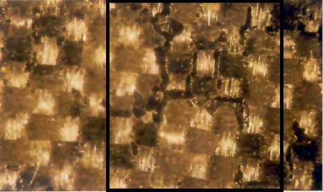 | Photograph (d). Microphotograph of crack propagation in low fatigue stress 290MP |
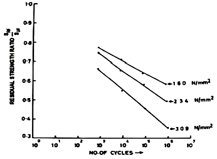
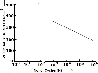 | Figure 4. Residual Flexural Strength at Different Cycles of Bidirectional Woven Carbon/Epoxy Composite after Cyclic Stress 309N/mm2 |
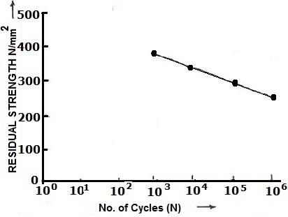 | Figure 5. Residual Flexural Strength at Different Cycles of Bidirectional Woven Carbon/Epoxy Composite after Cyclic Stress 234N/mm2 |
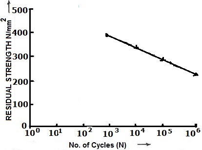 | Figure 6. Residual Flexural Strength at Different Cycles of Woven Carbon/Epoxy Composite after Cyclic Stress 160N/mm2 |
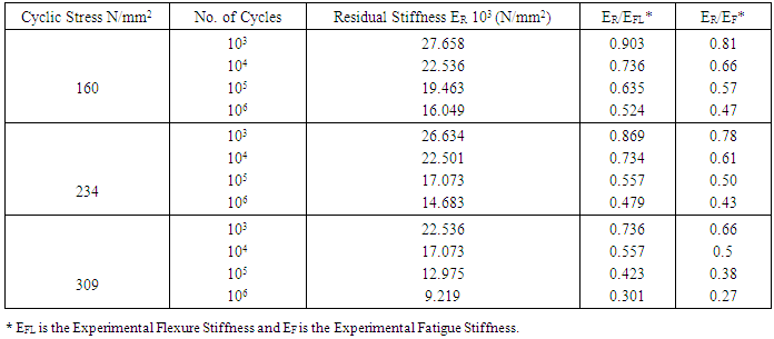
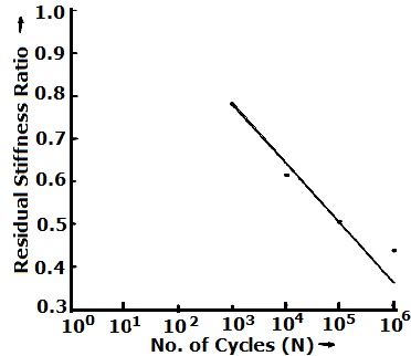
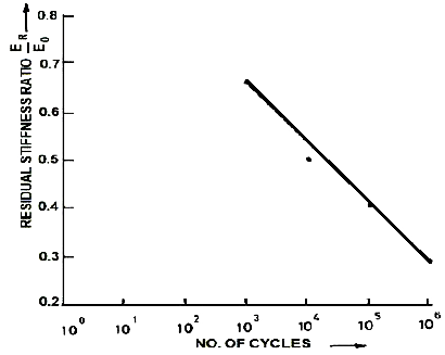
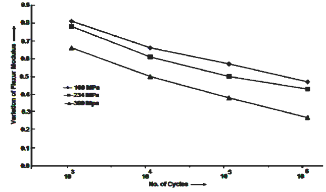
 Thus, stiffness changes are depended on the change of the apparent modulus (Table-3). The modulus related to matrix is most affected by the fatigue process. In a single lamina, the modulus of fiber might be least affected. But, the specimen carried number of laminae and interlaminar properties which are affected and simultaneously affecting the stiffness. Delamination that occurred during the fatigue loading is one of the causes of reduction in apparent modulus of tested specimens.In present observation, the material stiffness was found considerably reduced by fatigue stress. It has been observed that there is a reduction of stiffness round to 19% to 53% in between 103 cyclic ranges to 106 cyclic at 160MPa cyclic stress. This percentage was increased to 22% to 57% for 234MPa and 34% to 73% for 309MPa fatigue stress (Table-3, Fig.7, 8, 9, 13 and 14).
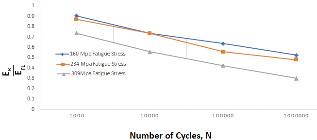
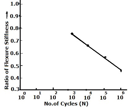 | Figure 7. Ratio of Residual to Ultimate Flexural Stiffness of Bidirectional Woven Carbon/Epoxy Composite at Different Fatigue Cycles after Cyclic Stress 160 N/mm2 |
 | Figure 8. Ratio of Residual to Ultimate Flexural Stiffness of Bidirectional Woven Carbon/Epoxy Composite at Different Fatigue Cycles with Cyclic Stress 234 N/mm2 |
 | Figure 9. Ratio of Residual to Ultimate Flexural Stiffness of Bidirectional Woven Carbon/Epoxy Composite at Different Fatigue Cycles with Cycle Stress 309N/mm2 |
 | Figure 10. Ratio of Residual Flexural Strength with Ultimate Flexural Strength of Bidirectional Woven Carbon/Epoxy Composite at Different Fatigue Cycles |
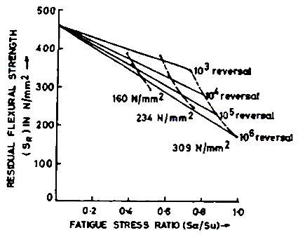 | Figure 11. Fatigue Stress ratio vs. Residual Flexural Stress at Different Fatigue Cycles |
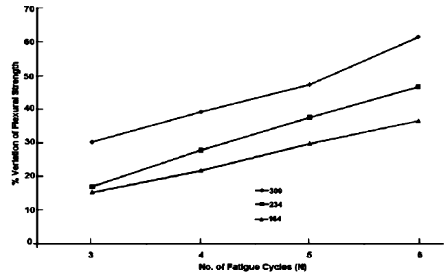 | Figure 12. Variation Percentage of Flexural Strength at Different Range of Cyclic Damage w.r.t. Original Flexural Strength |
 | Figure 13. Variation of Residual Flexure Stiffness with respect to Actual Flexure Stiffness of Fatigue Sample at Different Fatigue Cycles |
 | Figure 14. Variation of Residual Flexure Stiffness with respect to Actual Flexure Stiffness of ASTM Sample at Different Fatigue Cycles |
4. Conclusions
- Based on the experimental results, the following conclusions have been drawn. That,1. The residual strength of the cyclic stressed bidirectional woven carbon/epoxy composite laminates produced significant stress reduction with respect to increased number of cycles and increased value of cyclic stress.2. Also, a significant reduction in residual stiffness have been noted as the fatigue duration increased and sizably effected with respect to time interval of fatigue loading.So, it can be very easily understood that if the damaged specimen run for higher number of cycles without care there is sever strength decrement and may cause the structural failure.
ACKNOWLEDGEMENTS
- The authors want to express their sincere gratitude to DRDO for providing fund during this research and also express sincere thanks to BIT Mesra, MLRIT and KIIT for providing facility to conduct the experiments.