-
Paper Information
- Paper Submission
-
Journal Information
- About This Journal
- Editorial Board
- Current Issue
- Archive
- Author Guidelines
- Contact Us
International Journal of Composite Materials
p-ISSN: 2166-479X e-ISSN: 2166-4919
2017; 7(3): 103-114
doi:10.5923/j.cmaterials.20170703.03

Semi-Membrane and Effective Length Theory of Hybrid Anisotropic Materials
 Abstract
 Reference
 Full-Text PDF
 Full-text HTML
1School of Architecture, University of Utah, Salt Lake City, USA
2Department of Architecture, Yeung Nam University, Tae Gu, Korea
Correspondence to: S. W. Chung, School of Architecture, University of Utah, Salt Lake City, USA.
| Email: |  |
Copyright © 2017 Scientific & Academic Publishing. All Rights Reserved.
This work is licensed under the Creative Commons Attribution International License (CC BY).
http://creativecommons.org/licenses/by/4.0/

Among different shell theories, semi-membrane shell theory of isotropic materials is known to be developed nearly a century by Vlasov and it has been efficiently utilized to design and analysis. The aerospace vehicle structures and rocket fuel storage tanks designed efficiently however not much for composite materials, while most of recent structural materials are of the combination of anisotropic materials. This paper developed the theory for multiple combination of composite materials by means of asymptotic integration method starting from a three dimensional elastic element. The semi-membrane cylindrical shell theories are classified as that of very long effective length scale and we adopted here the longest possible longitudinal and short circumferential length scales, respectively, for the formulation. The edge effects due to the prescribed boundary condition penetrate differently depending on material orientation of each layer but all within the limit of length scale (ah)1/2 where Donnell-Vlasov bending theory is valid. Demonstrated that beyond the limit of edge effective zone, membrane or pseudo-membrane state dominates, it is traditionally named semi-membrane state. Governing equations of semi-membrane theory of cylindrical shell are formulated and the physical interpretation of the theory is described. The theory is very useful to analyze and design long cylindrical shells such as rocket fuel storage tanks, open top oil stage tanks and chimney structures.
Keywords: Semi-membrane theory, Pseudo-membrane theory, Donnel-Vlasov theory, Edge effect
Cite this paper: S. W. Chung, G. S. Ju, Semi-Membrane and Effective Length Theory of Hybrid Anisotropic Materials, International Journal of Composite Materials, Vol. 7 No. 3, 2017, pp. 103-114. doi: 10.5923/j.cmaterials.20170703.03.
1. Introduction
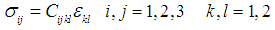
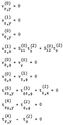
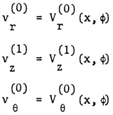
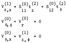
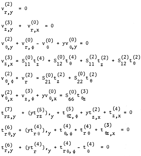
- Cylindrical shells are used for space shuttles, rocket fuel storage tanks, aircraft fuselages, above ground fuel storage tanks and deep water submarines. Depending on the environment where the shell structures are located, it will take positive or negative pressure, we must assure that the structure should be properly designed and never be collapsed. The advantages of cylindrical shells are not only its functional capacity and aerodynamic features but also a simple coordinate system for the mechanical analysis compared to spherical or conical shapes. For a shell of general shape we will first accept and use the classical assumption of Love then compare our theory with more elaborate theories of Reissner and Donnell-Vlasov as shown in the References [1-3]. It is known that Vlasov during the course of simplifying his cylindrical shell equation named Donnell-Vlasov theory he had noticed a proper equation for long longitudinal length, it is interesting that he might have invented the mathematics but never used the terminology “semi-membrane” at all. Who started to name the terminology and how Vlasov was honored are an interesting issue. When analyzing the cylindrical shells, it is common to utilize known physical parameters such as radius (a) thickness (h) and length (L). Donnell, Vlasov and many other scientists classified when develop the analytical model for circular cylindrical shell as following categories: Short and Intermediate effective length, very long effective Length.Once we built the analysis for the cylindrical shells we could easily convert to the other shape shells as shown in the References, [8, 17, 16, 19, 20]. However, the mathematics to describe its behavior and characteristics are complicated and it is more of challenge when the materials are anisotropic and combination of different anisotropic materials, hybrid anisotropic shell structures. Let us first start with three dimensional coordinate system of shell structures.The system is of longitudinal (X, z), circumferential (φ, θ) and radial (r) as shown in Figure 1 and 2. The original and non-dimensional coordinates as shown in the figures are used to allow an asymptotic integration process. According to the exact three-dimensional theory of elasticity, a shell element is considered as a volume element. All possible stresses and strains are assumed to exist and no simplifying assumptions are allowed in the formulation of the theory. We therefore allow for six stress components, six strain components and three displacements as indicated in the following equation:
 | (1) |
 | Figure 1. Coordinates of the Cylindrical Shell |
 | Figure 2. Normal and Shear Stresses |
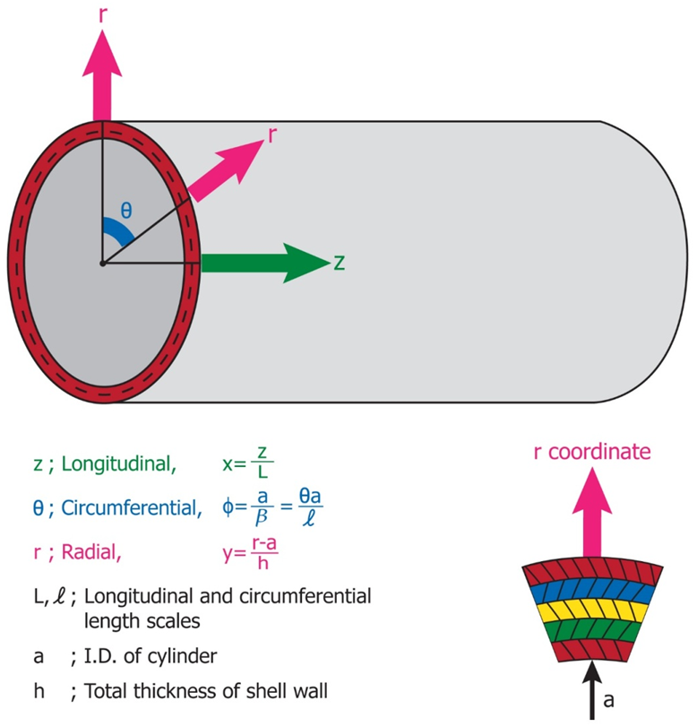
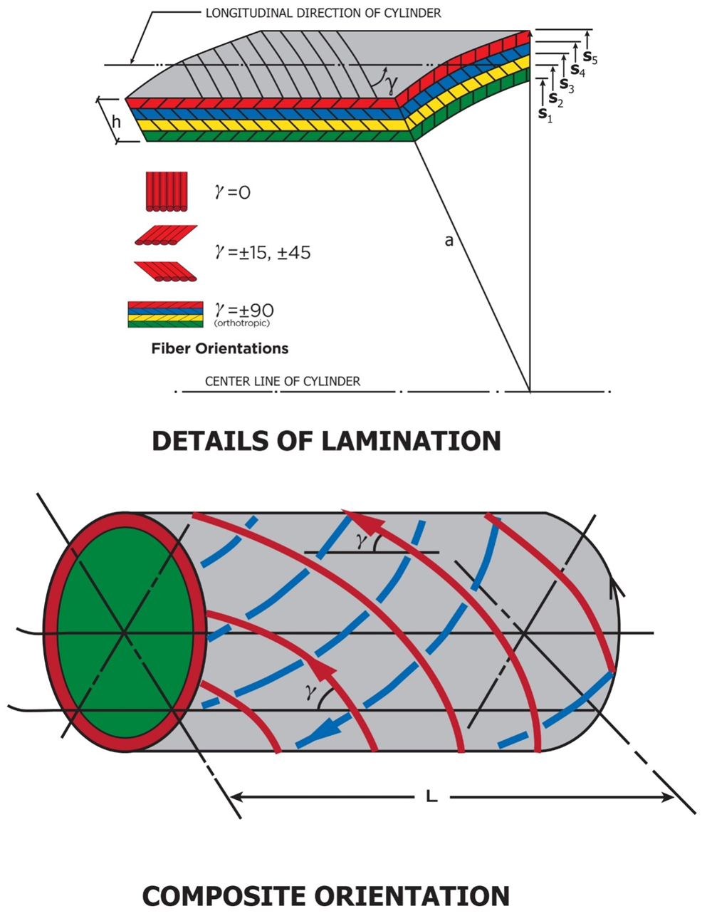 | Figure 3. A Laminated Cylindrical Shell, Material Orientation γ |
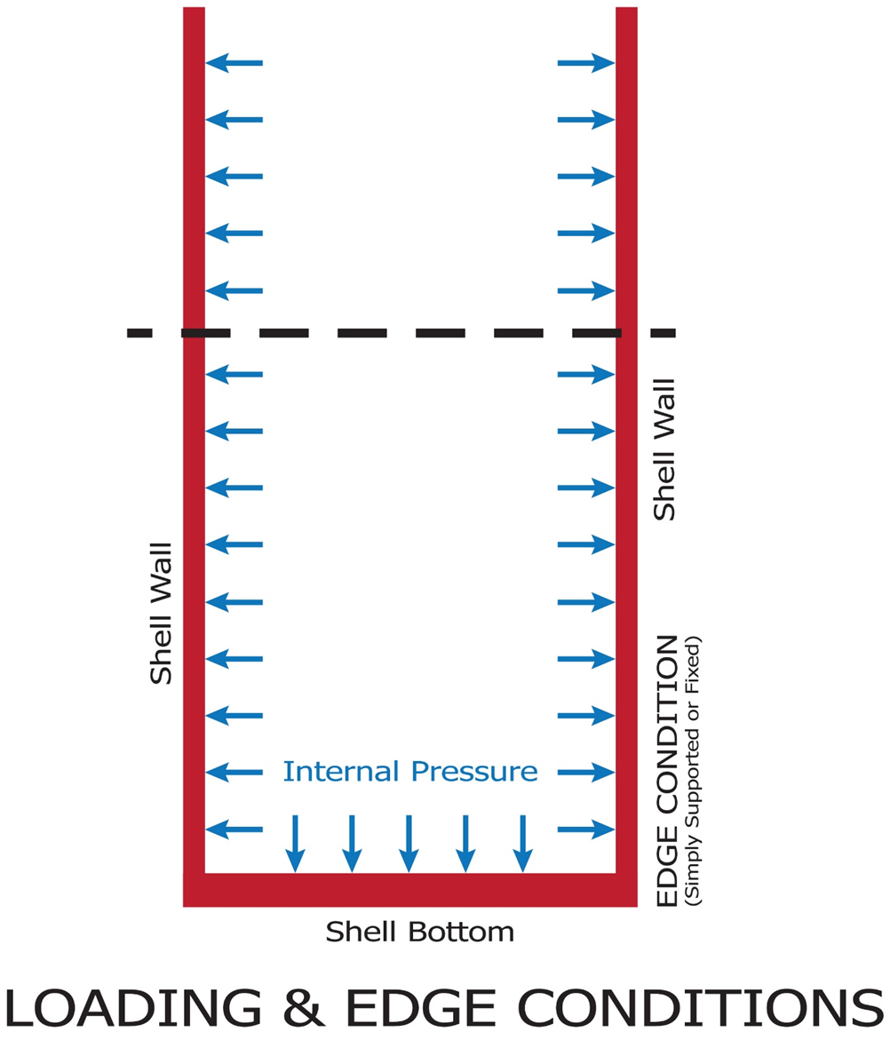 | Figure 4. Cylindrical Shell under Internal Pressure |
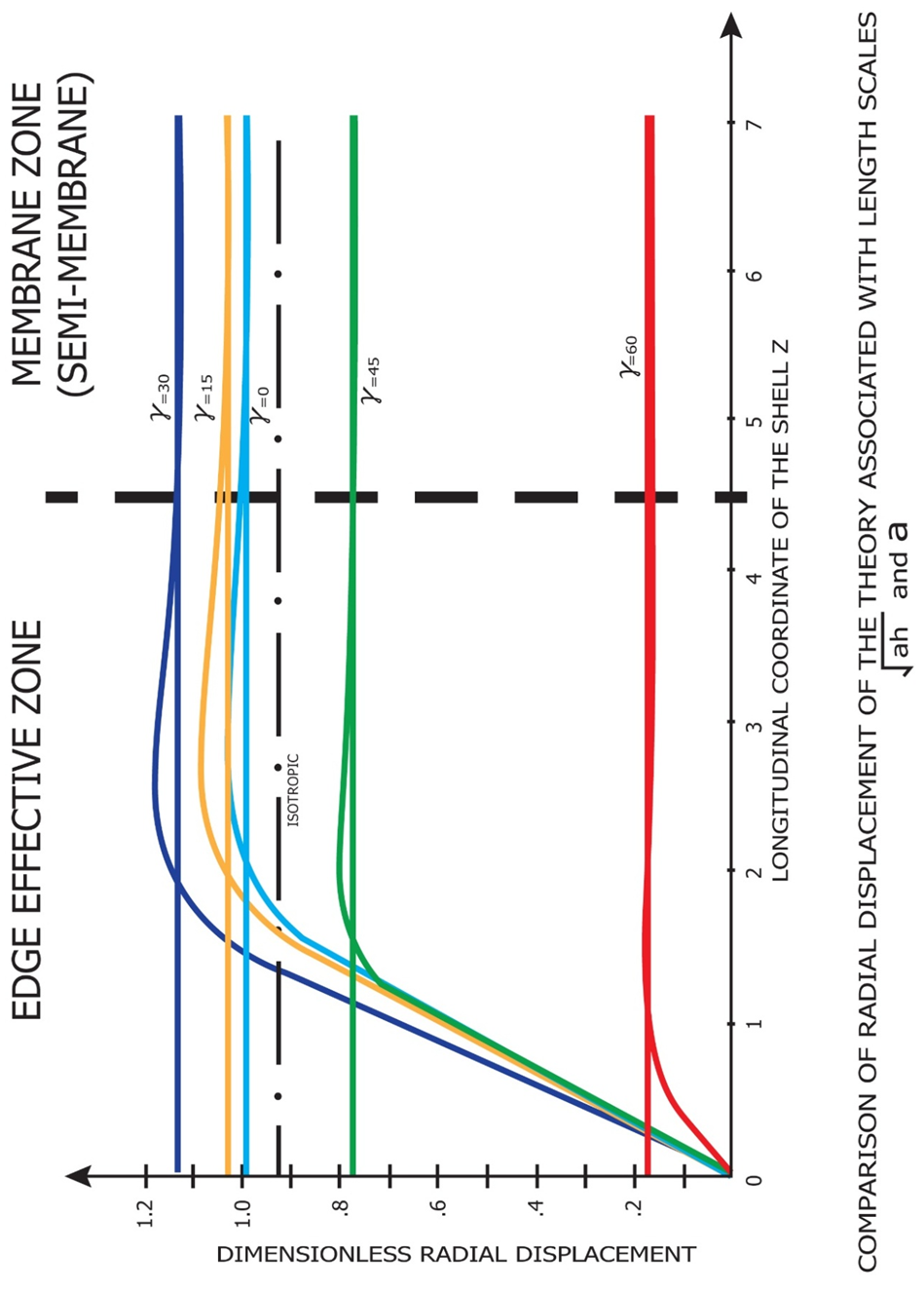 | Figure 5. Edge Effective Zone of Bending and Pure Membrane Theories |
 | (2) |
 | (3) |
 | (4) |
 | (5) |
 | (6) |
 | (7) |
 | (8) |
 | (9) |
 | (10) |
 | (11) |
 | (12) |
 | (13) |
 | (14) |
 | (15) |
 | (16) |
 | (17) |
 | (18) |
2. Conclusions
- Unlike the previous method of formulation we adopted to use asymptotic integration method and effective length scale concept. The theory of circular cylindrical shell is developed and formulated by adopting circumferential length scale as inner radius, a, and longitudinal length scale, a(a/h)1/2, which is the longest possible physical length and extended to hybrid anisotropic materials and the governing equations are well compared to classical theories of Vlasov, Calladine and Gould, etc. which are of isotropic material as shown in the references [6, 18] and [22] respectively.The adopted the circumferential length scale is equal to the inner radius, a, is membrane state circumferentially as shown in the pseudo membrane theory formulated by Chung and Hong as shown in the reference [13]. Longitudinally, a long length scale was adopted, therefore radial deformation and circumferential stresses are of exponentially decaying patterns as explained by Vlasov, Calladine and Vinson as shown in the references [6, 18] and [21] respectively.Due to the complexity of hybrid anisotropic material being used, the developed theory is of higher order partial differential equations but it should be considerably simplified considering the axi-symmetric nature of load and deformations and very long longitudinal length scale.The developed theory is very useful for the design of outer space rocket structures as well as open top oil storage tanks of composite materials.
ACKNOWLEDGEMENTS
- The research was sponsored by Summit Partners in Menlo Park, California, USA and graciously acknowledged.
List of Symbols
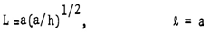
- a : Inside Radius of Cylindrical Shellh : Total Thickness of the Shell WallSi : Radius of Each Layer of Wall (i = 1, 2, 3 --- to the number of layer)L : Longitudinal Length Scale to be defined, Also Actual Length of the Cylindrical Shell Ei : Young’s Moduli in i DirectionGij : Shear Moduli in i-j FaceSij : Compliance Matrix of Materials of Each Layerr : Radial Coordinatel : Circumferential Length Scale to be defined
 : Angle of Fiber Orientationσ : Normal Stressesε : Strains Normalz, θ, r : Generalized Coordinates in Longitudinal, Circumferential and Radial Directions Respectivelyτ : Shear Stressesεij : Shear Strains in i-j Faceλ : Shell Thickness / Inside Radius (h/a)Cij : Elastic Moduli in General X, φ, Y : Non Dimensional Coordinate System in Longitudinal, Circumferential and Radial Directions Respectively