-
Paper Information
- Paper Submission
-
Journal Information
- About This Journal
- Editorial Board
- Current Issue
- Archive
- Author Guidelines
- Contact Us
International Journal of Composite Materials
p-ISSN: 2166-479X e-ISSN: 2166-4919
2017; 7(1): 20-36
doi:10.5923/j.cmaterials.20170701.03

Low-Velocity Impact Response and Damage Mechanism of 3D Fiber-Metal Laminates Reinforced with Amino-Functionalized Graphene Nanoplatelets
 Abstract
 Reference
 Full-Text PDF
 Full-text HTML
Zohreh Asaee, Mbarka Mohamed, Davide De Cicco, Farid Taheri
Advanced Composite and Mechanics Laboratory, Department of Mechanical Engineering, Dalhousie University, Canada
Correspondence to: Farid Taheri, Advanced Composite and Mechanics Laboratory, Department of Mechanical Engineering, Dalhousie University, Canada.
| Email: |  |
Copyright © 2017 Scientific & Academic Publishing. All Rights Reserved.
This work is licensed under the Creative Commons Attribution International License (CC BY).
http://creativecommons.org/licenses/by/4.0/

The low-velocity impact response of graphene nanoplatelets (GNP) reinforced 3D fiber metal laminates (3DFML) is experimentally investigated. Two types of GNPs, pristine GNP (PG) and amino-functionalized GNP (NH2-G), are used strategically to reinforce the resin used to mate the two main constituents of the 3DFMLs. In order to establish the most optimal GNP content with respect to the impact response of 3DFML, three different weight-percentages of GNPs are considered and the responses are compared against that of the baseline specimens. The seven groups of specimens are subjected to three different impact energies. The results reveal that 1 wt% NH2-G is the optimal content, which could generate the greatest enhancement in resistance of the hybrid composite against impact, and minimizing the damage extent in the 3DFMLs. The study provides an in-depth analysis of force- and displacement-time history curves, force-displacement response, energy absorption capacity and damage mechanisms of the affected areas for all four groups of specimens.
Keywords: Fiber-metal laminate, Nanoparticles, Low-velocity impact, 3D fabric, Graphene nanoplatelets, Functionalized nanoparticles
Cite this paper: Zohreh Asaee, Mbarka Mohamed, Davide De Cicco, Farid Taheri, Low-Velocity Impact Response and Damage Mechanism of 3D Fiber-Metal Laminates Reinforced with Amino-Functionalized Graphene Nanoplatelets, International Journal of Composite Materials, Vol. 7 No. 1, 2017, pp. 20-36. doi: 10.5923/j.cmaterials.20170701.03.
Article Outline
1. Introduction
- Three-dimensional Fiberglass/Metal Laminates (3DFMLs) are a recently developed class of Fiber Metal Laminates (FML), consisting of 3D Fiber-Glass Fabric (3DFGF) and sheets of magnesium or other types of light-weight metallic alloys. Therefore, the major difference between this new FML and its traditional counterparts is in the use of a recently developed truly 3D E-glass fabric. When combined with a suitable polymeric resin, this new 3DFGF enables the FML to offer significantly more enhanced mechanical response in comparisons to the traditional FMLs made of 2D fabrics. Attributes such as superior specific bending stiffness and strength, light weight, high energy-absorption capacity under impact loadings, excellent thermal insulation and acoustic damping are some of the positive advantages of this new FML. The superior performance of this new bread of FML makes them suitable for applications in automotive, aerospace, marine and other weight-sensitive engineering applications [1]. The first generation of 2D FMLs were developed by researchers at the Delft University in the early 1980s [2-5]. The main attributes and advantages of the FMLs were noted as high specific strength and stiffness, better tolerance to fatigue crack growth, and good formability [6]. Since then, various categories of FMLs have been formed and marketed, which are distinguished based on the type of metal, and type and configuration of fibers/cloths used to form them. Moreover, because of their relatively superior damage tolerant attributes, many researchers have explored and investigated the response of those FMLs under low-velocity impact (LVI) [7-22].In parallel, many researchers have also explored the possibility of gaining improvement in performance of fiber-reinforced plastic composites (FRPs) under LVI by addition of nanoparticles to the resins used to form FRPs [23-29]. For instance, Soliman et. al. [30] considered the LVI response of thin woven carbon fabric reinforced epoxy FRP. The investigated epoxy resin contained functionalized multi-walled carbon nanotubes (MWCNTs). Three different weight percentages of MWCNTs were considered: 0.5 wt%, 1 wt% and 1.5 wt%. The impact tests were performed at five levels of energy. The impact responses of tested composites and resulting damage mechanisms were examined and compared for each percentage of MWCNTs. The addition of functionalized MWCNTs was observed to have improved the impact response of the tested FRPs, and also limiting the extent of damage in the impacted specimens. A significant improvement in energy-absorption (approximately 50%) was attained when the resin contained only 1.5 wt% MWCNTs. In another study, Lin et al. [31] performed LVI tests on an epoxy reinforced with various nanoparticles. Two types of nanoparticles (i.e., titanium dioxide and cloisite 30B) were used. Two to 10% nanoparticle volume contents were considered in their investigation. The results showed that the addition of the nanoparticles improved the performance of the resin markedly. Particle exfoliation and uniformity in particle dispersion significantly affected the response. Moreover, it was shown that the tensile strength, loss modulus, impact strength and dynamic thermal rheology of nanocomposites were all highly affected by the geometry, temperature, volume and type of filler content, and uniformity in the dispersion of the nanoparticles.In another study, Haq et al. [26] studied the low-velocity impact response of sandwich composites comprising of glass fiber sheets and PVC foam with nano-graphene platelets (GNP) dispersed in the external layers of face sheets. The results of LVI tests of GNP doped specimens were compared with the pristine (i.e., with no GNP) specimens to investigate the influence of GNP on the impact response and damage extent in the specimens. They observed their GNP-doped specimens could absorb a greater amount of energy and exhibiting less damage extent in comparison to the pristine specimens.
2. Motivations and Objectives
- The 3D fiber metal laminates introduced in this work, as illustrated in Figure 1, consist of a foam-filled truly 3D E-glass fabric, sandwiched between magnesium alloy (MgA) sheets. As explained in the previous works of authors [32-35], this 3DFML and its other configurations were developed with the aim of utilization as body panels in passenger and other transport vehicles. These 3DFMLs exhibit different damage mechanisms when compared to the conventional FMLs. The most significant difference is that in these panels, delamination occurs only at metal/3DFGF interfaces, with no delamination occurring within the fabric. As a result, FMLs made of 3DFGFs produce significantly greater energy-absorption capacity in comparison to their conventional 2D FML counterparts. The main goal of this study is, therefore, to enhance the interface bond strength of these 3DFMLs cost-effectively, so to further improve their performance by mitigating the potential interface delamination. For that, the epoxy resin used for bonding the metal sheets to 3DFGF is reinforced with relatively inexpensive graphene nanoplatelets (GNPs). GNPs were selected as an effective reinforcement because of their superior mechanical properties and significantly lower cost compared to the other forms of nanocarbons (i.e., carbon-nanotubes, multi-walled carbon-nanotubes and Nano-carbon fibers). Moreover, Ahmadi-Moghadam et al. [36] demonstrated that functionalization of GNP nanoparticles significantly improved the nanoparticles/ epoxy matrix interface strength. They examined three different functionalization techniques on their GNPs (i.e., graphene oxide [GO], silane modified GNPs (G-Si) and amino functionalized GNP [NH2-G]), and compared the results with those obtained from the pristine GNPs. Their results showed that G-Si and NH2-G functionalized GNPs provided the most efficient improvement in the mechanical properties of their GNP-reinforced epoxy composites. Thus, the NH2-functionalized GNP is considered for investigation in this study. Therefore, the impact response of 3DFML panels formed by resin reinforced with pristine and NH2-functionalized GNPs will be investigated and compared to the response of 3DFML panels formed by neat epoxy. In addition, in order to establish the optimal GNP content for gaining the maximum enhancement in LVI response of 3DFMLs and mitigating the extent of their damage, three different weight contents (wt%) of GNPs are considered in this investigation (i.e., 0.5, 1 and 2 wt%).
3. Experimental Investigation
3.1. Materials
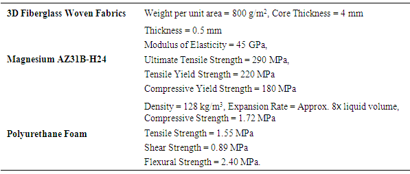
- As stated earlier, GNP-reinforced 3DFMLs (referred to as GNP-3DFML hereafter), were manufactured from thin (0.5 mm) sheets of AZ31B-H24 MgA and the 3D E-glass fabrics. The sheets were acquired through the Metalmart International (Commerce, CA). The 3DFGF was acquired through China Beihai Fiberglass, Co. Ltd. (Jiujiang City, China). The fabric was wetted by an epoxy resin. Araldite LY 1564 (Bisphenole-A) resin with its hardener, Aradur 2954 (cycloaliphatic polyamine), supplied by the Huntsman Co. (West Point, GA) were used. The resin is a low viscosity and warm curing epoxy resin. The mixing ratio was 100:35 parts by weight as recommends by vendor. To further enhance the mechanical performance of the 3DFGF-reinforced epoxy composite, an 8-lb polyurethane foam (US Composites, West Palm Beach, FL 33407) was used to fill the hollow cores of the fabric (see Figure 1). This composite was then sandwiched in between two sheets of magnesium alloy. The resin used to mate the 3DFGF and magnesium sheets was mixed by pristine GNP nanoparticles obtained from XG Science (Lansing, MI). The average thickness, t, and average particle diameter, D, of GNP was 7 nm and 25 μm, respectively (See Figure 2). Amino-functionalized GNP (NH2-G), with an average diameter of 8 μm and average thickness of 5 nm were provided through Cheap Tubes Inc. (Brattleboro, VT). The mechanical properties of the 3DFGF, magnesium sheet, epoxy resin, polyurethane foam and GNP are presented in Table 1.
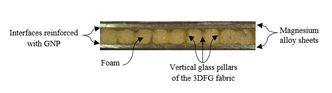 | Figure 1. The detail of the GNP- reinforced 3D fiber metal laminate (GNP-3DFML) |
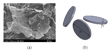 | Figure 2. (a) SEM image of typical GNPs used in this study, and (b) their idiazied schematic [37] |
|
3.2. Procedures
- In the first stage, the epoxy resin and its hardener were mixed using an electric paddle mixer at 100 rpm for 10 min, and then degassed in a vacuum chamber at room temperature for an hour. Afterwards, the mixture was applied onto the 3DFGF and cured in an oven for two hours at 60°C and eight hours at 120°C, per the manufacture instructions. Then, the two-parts polyurethane foam were mixed and injected by a syringe into the hollow cores of the foam. As stated, the resin used to mate the cured 3DFGFand magnesium sheets was reinforced with pristine and NH2-functionalized GNPs. For that, the same epoxy used for fabricating the 3DFGF, was reinforced by the two types of GNP particles. The GNP particles were first thoroughly mixed into the resin using the electric paddle mixer at 1000 rpm for 15 min. Afterwards, the GNP-resin slurry was passed through a three-roll mill (Torrey Hill Technology, San Diego, CA) to uniformly disperse the GNP particles following the optimized procedure outline in reference [37]. Subsequently, the hardener was added to the GNP-resin mixture and degassed in a vacuum chamber at room temperature. The mixture was then used to adhere the cured 3DFGF and two magnesium sheets. Before doing so, the bonding surfaces of Mg sheets were first sand-blasted with 20/40 grit sand and the sanded surfaces were cleaned with compressed air, and then wiped clean with acetone. The GNP-epoxy mixture was applied to both mating surfaces, and the 3DFML assembly were vacuum-bagged and let cure for two hours at 60°C, and then for eight hours at 120°C.
3.3. Testing Procedure
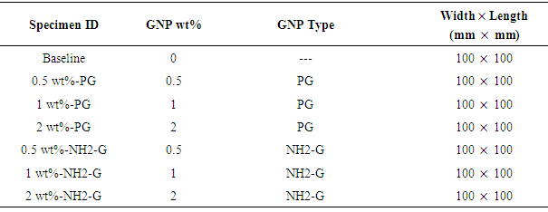
- A total of 63 specimens were fabricated and categorized into seven groups based on the GNP type (pristine GNP (PG) and NH2-funtionalized GNP (NH2-G)), and their weight content (see Table 2). The specimens were then subjected to three different levels of impact energies. The energy levels were selected based on our previous investigations [34]. The specifics of the tested specimens are presented in Table 2.
|
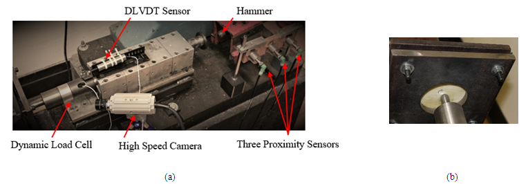 | Figure 3. (a) The Impact test equipment, (b) The fixture used to hold the specimen |
4. Results and Discussions
4.1. Load- and Displacement-Time Histories
- As mentioned earlier, a total of 63 specimens were tested under three different impact energy levels. Figure 4 illustrates the force- and displacement-time histories of all seven groups of specimens subjected to three different energy levels. As can be seen, the impact force-time history curve of each group of specimens (i.e., regardless of GNP type and wt% content) essentially plateaus at almost the same magnitude of force. The variation of the load-history curves before attaining their peak values is quasi-linear. The slope of this portion of the curves (which is referred to as the “contact stiffness” [27]) is lower for the baseline specimens; however, the slopes of the curves of specimens reinforced with PG or NH2-G are quite similar, regardless of wt% GNP content. At relatively low impact energies (i.e., the energy levels that caused no perforation), the contact stiffness varies quasi-linearly until a damage develops on the impacted surface of the specimens. An abrupt change in the curve signifies the development of a crack on the impacted surface. After this stage, the impactor bounces back, and the force decreases to zero. At the higher impact energy level (i.e. energy levels causing perforation), the force increases with an almost linear variation with respect to time, but with a high rate, and then decreases abruptly once the impactor perforates the specimens. The sharp decrease in the load, as opposed to sudden decrease of it to zero, is due to the friction between the impactor’s body and perforation boundary. In the case of baseline specimens, the impactor partially perforated through the specimens and caused a crack on the non-impacted surface, followed by bouncing-back of the impactor. The response can also be depicted through examination of the load- and displacement-time history curves. The force-time history curves of the PG and NH2-G specimens impacted at impact energy of 40J are quite similar, signifying that the impactor did not perforate into the specimens, but generated a crack or permanent deformation on the impacted surface. This is also confirmed by the variations seen in the displacement-time history curves, which indicates that the impactor generated a crack and bounced back without perforating the specimens. The force-time history curves of PG specimens, subjected to 40 J impact energy attained their maximum values almost at the same magnitude; nevertheless, specimens with 1 wt%-PG exhibited the longest contact duration. In the case of NH2-G group of specimens, the maximum contact force increased by 27% and 14% in 1 wt%-NH2-G and 2 wt%-NH2-G specimens, respectively, in comparison to the baseline specimens. Moreover, the contact time of these two groups of specimens increased by 35% and 48% respectively. Moreover, the comparison of displacement-time history curves of both PG and NH2-G groups of specimens reveals that inclusion of GNP enabled the specimens to undergo more deformations (by a maximum of 46% for 1 wt%-NH2-G and 91% for 1 wt%-PG) prior to stress-softening. It should be noted that inherently, 3DFMLs respond to impact load in a ductile manner. The comparatively larger observed deformation response implies improved ductility of their response. This observation, concludes that, at 40 J impact energy, inclusion of 1 wt% of PG and NH2-G nanoparticles offers the greatest improvement in the ductile response of 3DFML panels. The time histories of all four groups of specimens, subjected to 50 J impact energy is also illustrated in Figure 4. Examination of the displacement-time history curves would reveal that the PG group of specimens experienced perforation when subjected to 50 J energy, while specimens with 0.5 wt% and 1 wt% GNP content resisted perforation. In contrast, the time history curves of specimens with 2 wt%-PG content and baseline specimen evidence through-thickness perforation of specimens by the impactor. The maximum contact forces observed for the baseline and 1 wt%-PG specimens are comparable; however, the contact force decreased in specimens with 0.5 wt%-PG and 2 wt%-PG contents. In fact, the 0.5 wt% and 1 wt%-NH2-G specimens that were subjected to 50 J impact energy experienced a sequence of cracking, but no perforation. Specifically, crack developed on the impacted surface of specimens with 0.5 wt% NH2-G, while another crack developed on the other surface of the specimens that contained 1 wt%-NH2-G. The first decrease in the force history curves of these specimens is associated with the creation of the first crack. As seen, the load capacity increases after this stage, followed by a subsequent abrupt decrease in load capacity, indicating the development of a crack on the non-impacted surface. The maximum contact force increased by 22% in specimens with 1 wt%-NH2-G in comparison to the contact force of baseline specimens. The shape of the force history curve and larger displacement endured by specimens with 2 wt%-NH2-G indicates the perforation of those specimens when subjected to 50 J impact energy. Moreover, the ductile response observed in the specimens under 40 J impact event was also observed at 50 J event for both PG and NH2-G specimens. Moreover, specimens with NH2-G and PG contents endured approximately 30% and 84% more displacement, respectively, compared to the baseline specimens. In the 60 J impact events, the impactor penetrated into all baseline and nano-reinforced specimens. However, specimens with 2 wt% PG content endured a larger deformation and lower contact force in comparison to the baseline specimens. The maximum contact force experienced by 0.5 wt% and 1 wt% PG and 0.5 wt% and 2 wt% NH2-G specimens are almost identical to that sustained by the baseline specimens. However, examination of the last portion of the displacement-time history curves of specimens with 1 wt% PG and NH2-G content indicates that the impactor bounced back and did not thoroughly penetrate through the specimens. It can be therefore concluded that 3DFMLs with 1wt% PG and NH2-G contents showed greater perforation tolerance.
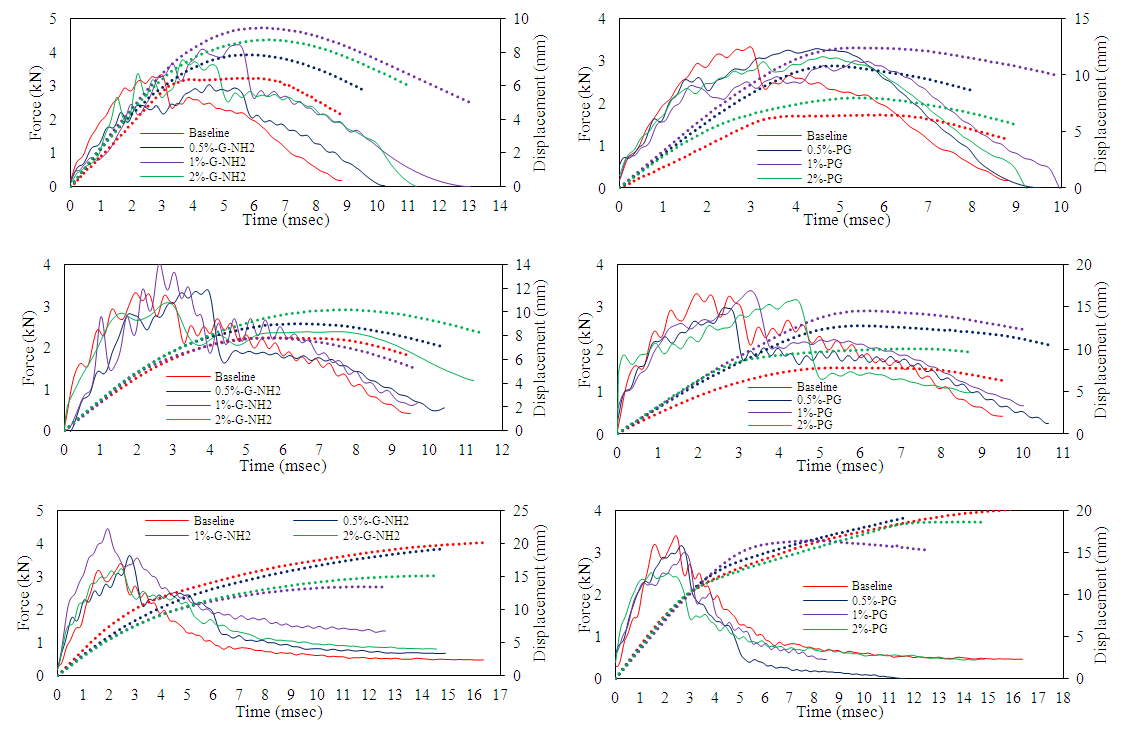 | Figure 4. Force- and displacement-time history responses of all specimen groups impacted at energy levels of 40 J (1st row), 50 J (2nd row) and 70 J (3rd row) |
4.2. Force-Displacement Response
- In this section, specimens’ behaviours are compared based on their force-displacement response, as illustrated in Figure 5. The initial slope of force-displacement curves represents the ‘impact bending stiffness’ of specimens [23]. It can be observed that under impact energy levels that did not result in a through-penetration, the addition of PG and NH2-G particles could not improve the impact bending stiffness of the 3DFMLs. The force-displacement graphs of GNP-based specimens indicate that the impactor rebounded after the initial impact. Moreover, the bending stiffness of specimens reinforced with PG and NH2-G are almost identical, but considerably larger than those exhibited by the baseline specimens. As can be seen from the results shown in Figure 5(c), when specimens were impacted at 70 J energy, all specimens, with the expectation of those with 1 wt% PG and NH2-G contents were perforated.
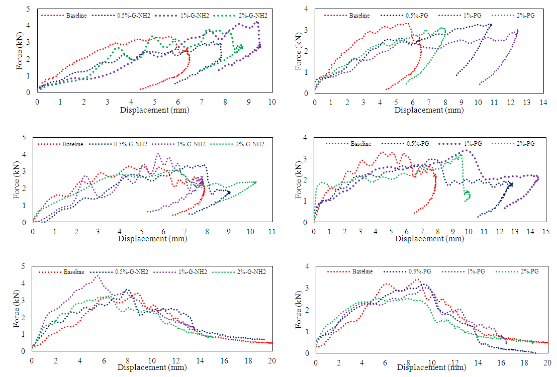 | Figure 5. Force-displacement curves of all specimen groups impacted at energy levels of 40 J (1st row), 50 J (2nd row) and 70 J (3rd row) |
4.3. Damage Mechanism
- Figure 6 illustrates the damage mechanisms of all seven groups of specimens subjected to the three different levels of impact energy. The damaged area of the impacted specimen is measured using a Dino-Lite digital microscope and its accompanying DinoCapture software. Figure 6 illustrates the post-test pictures of all groups of specimens tested at all three different impact energies. As seen from the results summarized in Figure 7, the damage area increased as impact energy was increased. Note that the variation in the damaged area in the non-impacted surface is greater than that observed on the impacted surface. The damage areas on the impacted and non-impacted surfaces of the baseline group of specimens impacted at 70 J energy increased by 32% and 416%, respectively, in comparison to those that were subjected to 40 J impact energy. This trend is also observed for the cases of PG and NH2-G groups of specimens.
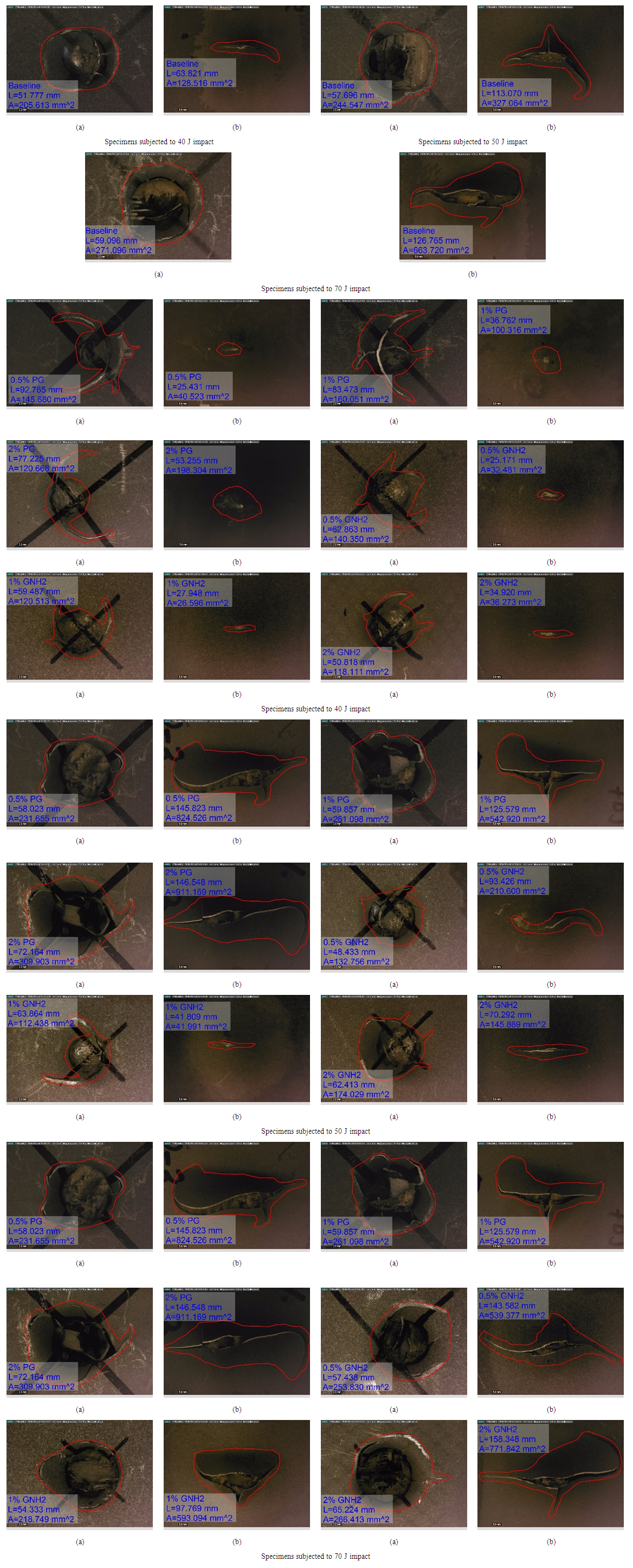 | Figure 6. Damage mechanisms of all groups of specimens (a) on the impacted surface and (b) on non-impacted surface |
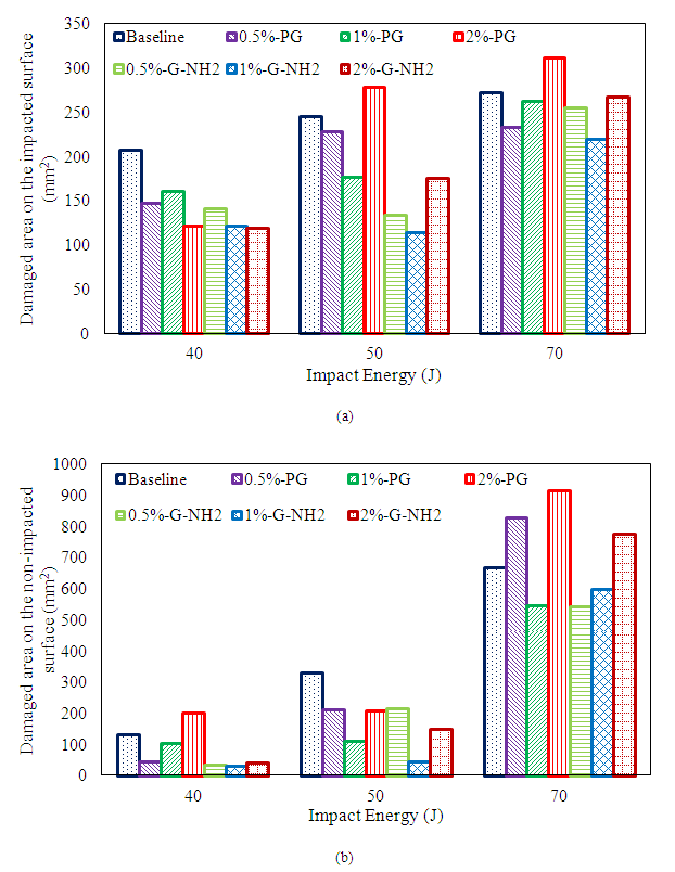 | Figure 7. Damaged area of impacted specimens on the (a) impacted surface, and (b) non-impacted surface |
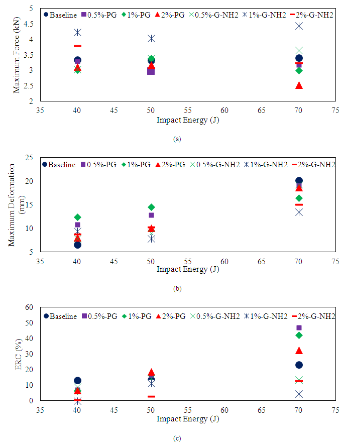 | Figure 8. Variation in (a) maximum force, (b) maximum deformation and (c) ERC as a function of GNP type and weight-content for the seven groups of specimens subjected to three different impact energy levels |
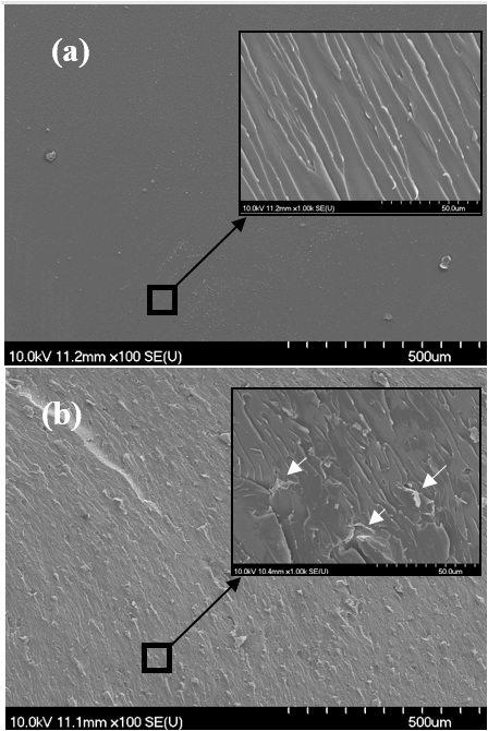 | Figure 9. Fracture surfaces of the resin reinforced with and without GNP particles; (a) neat resin, (b) 0.5 wt% [39] |
4.4. Global Features of GNP-3DFML
- As stated earlier, the main objective of present study has been the establishment of the effects of GNP nanoparticles on the impact response of a recently developed 3DFML. In this section, the global effect of addition of PG and NH2-G particles to the resin is summarized, and the optimal %wt of GNP content that could produce the maximum enhancement in 3DFML’s impact response is established. As discussed earlier, inclusion of PG in the resin did not produce any enhancement in the impact force endurance of the 3DFMLs. However, the inclusion increased the contact stiffness of 3DFMLs. Although, the inclusion of NH2-G improved impact force capacity of all specimens, regardless of wt% content, the most notable enhancement of 31% in the contact force was observed for the specimens with 1 wt% NH2-G content. Furthermore, inclusion of both PG and NH2-G nanoparticles increased the maximum local deformation that the specimens could sustain under all the applied impact energy levels. The corresponding results are presented and compared for all groups of specimens in Figure 8 (a) and (b). Moreover, the variation in the energy restitution coefficient (ERC) (a parameter that is a function of the absorbed impact energy [38]) as a function of GNP type and weight content is also illustrated in Figure 8 (c). The results indicate that specimens with NH2-G content exhibited the greatest levels of energy-absorption capacity among all groups of specimens. The ERC of specimens containing 1 wt% NH2-G (measured at the perforation level of impact energy), is greater by 80% and 89%, respectively, when compared to those of the baseline and 1 wt% PG-content specimens. Note that a lower value of ERC would indicate higher energy absorption capacity; therefore, specimens containing 1 wt% NH2-G exhibited the largest energy absorption capacity among all groups of specimens. On the other hand, when the %wt content of PG and NH2-G was increased to 2 wt%, degrading effects in both the impact capacity and damage area were observed. These degradations are attributed to the agglomeration of GNP particles, which results due to nonuniform dispersion of the particles when the content surpasses a certain value [31]. In summary, the collective results indicate that the addition of 0.5 wt% and 1 wt% PG and NH2-G nanoparticles within the resin used to mate the 3DFGF to MgA sheets would improve the ductility, deformability and energy-absorption capacity of the 3DFML. However, according to the experimental results, the optimal response could be attained at 1 wt% NH2-G content.
5. Summary and Conclusions
- The main objective of this study was to investigate whether the inclusion of graphene nanoplatelets (GNP), a relatively inexpensive nanocarbon particles, in the resin used to mate the constituents of a novel 3D fiber-metal laminate (3DFML), could enhance the performance of such FMLs under low-velocity impact loading state. Two different types GNPs, with four different wt% (weight percentage) GNP contents were considered (i.e., 0, 0.5, 1 and 2 wt%), so that the optimal GNP content could be established. In total, 63 3DFML specimens were fabricated and tested under three impact energies. The results revealed that specimens with resin containing amino-functionalized GNP particles (NH2-G) exhibited improved impact response in comparison to those containing pristine GNP (PG) or with no nanoparticles (i.e., neat epoxy). It was observed that the addition of 0.5 wt% and 1 wt% of PG and NH2-G to resin improved the ductility of 3DFMLs. Moreover, 3DFMLs with 0.5 wt% and 1 wt% GNP contents could sustain larger local displacement (hence were more resilient) than the baseline specimens and those with 2 wt% GNP content in the tests in which the energy levels were less than that causing perforation. In all, the 3DFMLs containing NH2-G showed better performance and energy-absorption capacity among all groups of specimens. Furthermore, this group also sustained less damage (i.e., in terms of the extent of damage areas developed on specimens’ surfaces, as well as the extent of through-thickness damage). The results also conclusively indicate that the optimal GNP content would be 1 wt%. When GNP content was increased to 2 wt%, the ductility and energy-absorption capacity of the 3DFML specimens were degraded in comparison to the baseline and specimens containing either 0.5 or 1 wt% GNP contents. This degradation is believed to be due to the agglomeration of GNP particles, causing non-uniform dispersion of the nanoparticles within the resin.
ACKNOWLEDGEMENTS
- This financial support received through the National Science and Engineering Research Council of Canada (NSERC) in support of this study is gratefully appreciated. The Killam scholarship awarded to the first author is also gratefully acknowledged.