S. W. Chung1, S. G. Hong2, D. A. Mendenhall3
1School of Architecture, University of Utah, Salt Lake City, USA
2Department of Architecture, Seoul National University, Seoul, Korea
3Independent Research Specialist, Salt Lake City, USA
Correspondence to: S. W. Chung, School of Architecture, University of Utah, Salt Lake City, USA.
| Email: |  |
Copyright © 2017 Scientific & Academic Publishing. All Rights Reserved.
This work is licensed under the Creative Commons Attribution International License (CC BY).
http://creativecommons.org/licenses/by/4.0/

Abstract
Due to the complex nature of hybrid anisotropic materials used for laminated circular cylindrical shells, computing the critical stresses under various boundary and loading conditions is more sensitive and therefore reasonable simplification of the governing equation is in big demand. This article first extended and developed the shell theory originally formulated by Donnell and Vlasov for isotropic materials to accommodate for hybrid anisotropic materials, then formulated for a simplified governing equation by means of adopting the asymptotic integration method of anisotropic elasticity theory and effective length scales. Comparison of two different shell bending theories is discussed. Also presented are proper choices of the governing equations for different loading conditions. The theories are created and extremely useful for sensitive anisotropic non-homogeneous materials, which can be applied to layered walls of cylindrical shells with various materials.
Keywords:
Shell Bending Theories, Flexural Moments and Stresses, Length Scales, Asymptotic Integration, Donnell-Vlasov Theory
Cite this paper: S. W. Chung, S. G. Hong, D. A. Mendenhall, Compare and Contrast Bending Shell Theories of Hybrid Anisotropic Materials, International Journal of Composite Materials, Vol. 7 No. 1, 2017, pp. 8-19. doi: 10.5923/j.cmaterials.20170701.02.
1. Introduction
In this paper, we will start with classical Love assumptions as described in the Reference [1] and the cylindrical shells in Reference [2] for conventional isotropic materials that is directionless Young’s modulus and developed the theories further for multiple anisotropic materials. Space shuttles, rocket fuel storage tanks, aircraft fuselages, above ground fuel storage tanks and pipelines are all cylindrical shells. The advantages are not only its functional capacity and aerodynamic features but also a simple coordinate system for the mechanical analysis compared to spherical or conical shapes. Also once we build the analysis for the cylindrical shells we can easily convert to the other shape shells as shown in the References [8, 17, 16, 19, 20].The coordinate system is of longitudinal (X, z), circumferential (φ, θ) and radial (r) as shown in Figures 1 and 2. The original and non-dimensional coordinates as shown in the figures are used to allow an asymptotic integration process. According to the exact three-dimensional theory of elasticity, a shell element is considered as a volume element. All possible stresses and strains are assumed to exist and no simplifying assumptions are allowed in the formulation of the theory. We therefore allow for six stress components, six strain components and three displacements as indicated in the following equation: 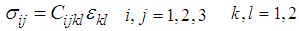 | (1) |
where σij and εkl are stress and strain tensors respectively and Cijkl are elastic moduli.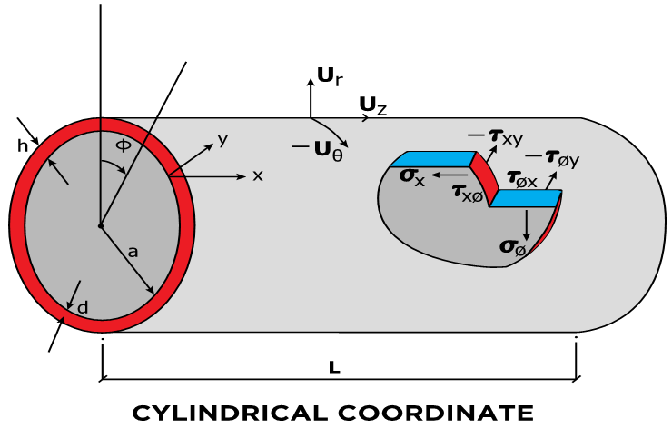 | Figure 1. Dimensions, Deformations and Stresses of the Cylindrical Shell |
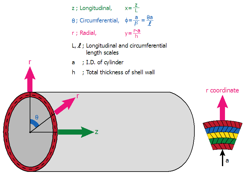 | Figure 2. Details of the Coordinate System |
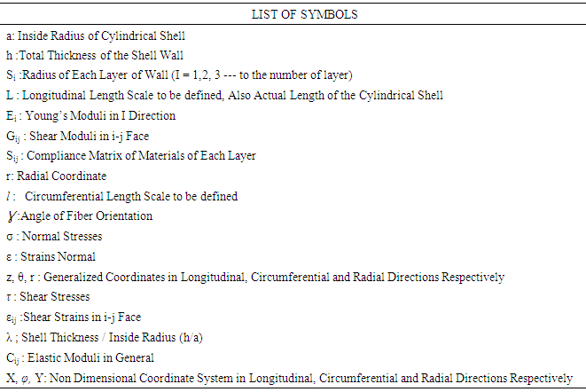
There are thus a total of fifteen unknowns to solve for in a three dimensional elasticity problem. On the other hand, the equilibrium equations and strain displacement equations can be obtained for a volume element and six generalized elasticity equations can be used. A total of fifteen equations can thus be formulated and it is basically possible to set up a solution for a three-dimensional elasticity problem. It is however very complicated to obtain a unique solution which satisfies both the above fifteen equations and the associated boundary conditions. This led to the development of various theories for structures of engineering interest. A detailed description of classical shell theory can be found in various references [1-13].Considering a small anisotropic free body diagram as shown in the Reference [13] and referring to the list of symbols, Table 1, we can formulate three equilibrium equations and six stress-displacement equations, all shown in the Reference [13] and [20]. Considering anisotropy and lamination of the materials we will introduce an angle, γ, being the angle between the principal axis of cylindrical coordinate and the principal angle of anisotropic materials of each layer, assuming all changing each layer, the material properties are transformed also shown according to seven equations as shown in the References [13] and [20]. Table 1. List of Symbols
 |
| |
|
Donnell, Bartdorf, Goldenveiser, Vlasov and many others, as shown in the References [2, 6, 8, 10, 13, 16-21] classified the cylindrical shell theories into the three categories as Very short effective length Intermediate effective length Long effective lengthThe lengths are compared to the cylinder radius and thickness.
2. Formulation of Simplified Bending Theory of Anisotropic Materials
As many investigators suggested we will develop the shell theories within the classification of intermediate effective length. More specifically, we foresee it is more practical and simplified solutions can be obtained by limiting our investigations within the intermediate length scale and long circumferential length scale as shown below and develop a cylindrical shell theory based on the length scales as follows: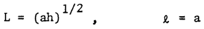 | (2) |
Where a is inner radius, h is the total thickness L is longitual length scale and ℓ is circumferential length scales respectively. The effective length scale of Equation (2) was efficiently used by Donnell, Bartdorf and Vinson in the References [2], [19] and [21] respectively. On substituting these length scales into equations of equilibrium and stress-displacement as explained earlier, we obtain:Stress-Displacement Relations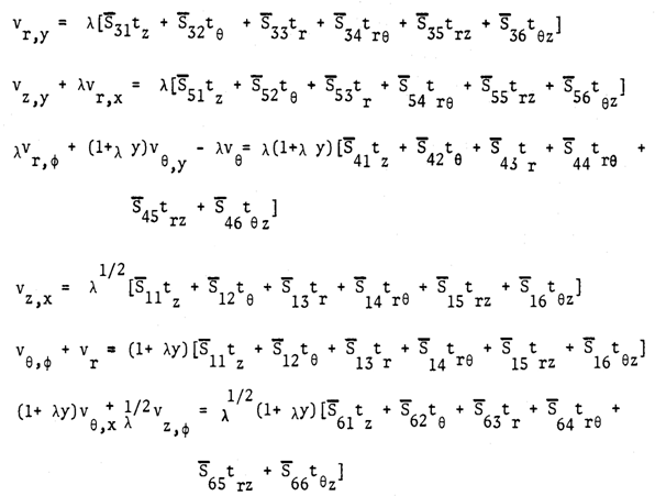 | (3) |
Equilibrium Equations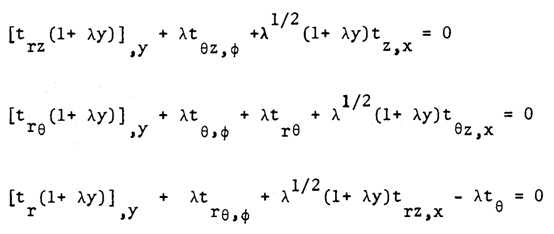 | (4) |
where symbols are as defined in the Table 1 and the Reference [13] and λ is total thickness (h) divide by inner radius (a), λ = h/a.We can now obtain the first approximation equations as follows: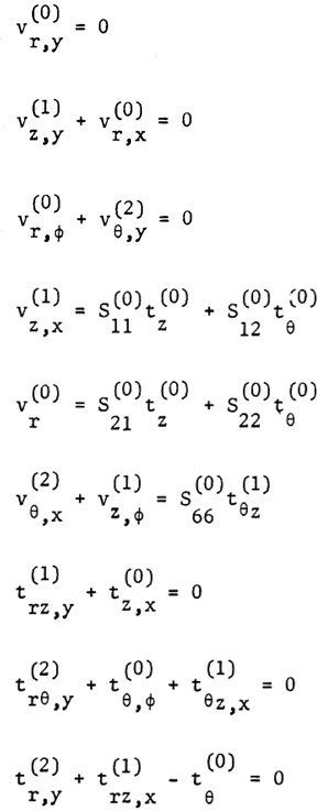 | (5) |
In the above, superscripts, 0, 1, 2 are the order of asymptotic expansion of each variables.From the inspection of equations (5) it is seen thata). The dominant stresses in this theory are the in-plane normal ones.The in-plane shear stress is of order λ1/2 compared to them.b) The radial, longitudinal and circumferential displacements are of order zero, one and two, respectively in λ1/2, while all the remaining in-plane components of compliance matrix are of zero order. Integration of the first three equations of (5) with respect to the thickness coordinate y yields,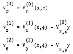 | (6) |
The middle three equations of (5) can now be solved for the in-plane stresses as follows: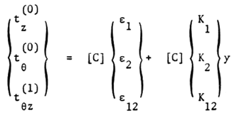 | (7) |
Where Cij (i,j = 1,2,3) are the components of a symmetric matrix given by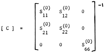 | (8) |
After substituting the equations and boundary conditions into the equations (3) and (4) we can arrive to the following governing equations of the theory.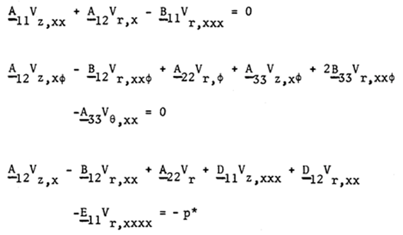 | (9) |
where 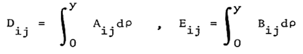 | (10) |
3. Formulation of Further Accurate Bending Theory of Anisotropic Materials
In case we need more accuracy for stress resultants and strain deformations, we can develop a theory associated with intermediate length scale and short circumferntial langth scale is developed by applying the length scales as follows: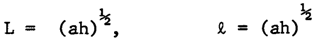 | (11) |
The following systems of differential equations are obtained by substituting the characteristic length scales (11) into the equations of equilibrium and stress-displacement as shown in the References [13] and [20], we obtain:Stress-Displacement Relations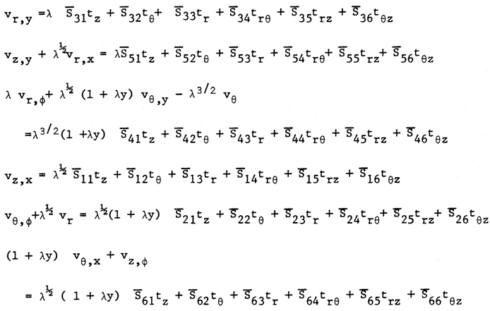 | (12) |
Equilibrium Equations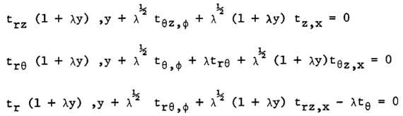 | (13) |
On substituting the asymptotic expansions for the displacements and stresses explained in the Reference [13] for the compliance matrix into equations (12) and (13), we obtain the following systems of equations representing the first approximation theory: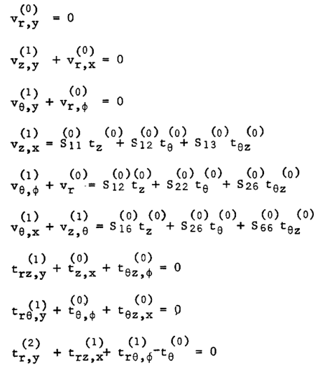 | (14) |
From the initial terms chosen for the first approximation system shown as superscript (0), we can observe the following aspects of the theory:a) The first three equations in (14) show that the transverse normal and transverse shear strains are zero and thus the classical hypothesis of the preservation of the normal appears in the theory.b) The dominant stresses are the in-plane ones. They are all of zero order while the transverse shear stresses are order of λ1/2 and the transverse normal stress is of λ compared to them.Integration of first here equation in (14) with respect to y yields 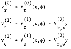 | (15) |
where vr , vƟ, vz are the components of displacement at y=0 surface. You will find the linear y dependence of the in-plane displacements. On substituting (15) into next three equations of (14), we obtain the in-plane stress-strain relations: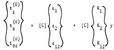 | (16) |
where strain components €i and curvature components ki defined at y = 0 surface are given as follows: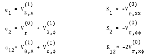 | (17) |
and [C] is the inverse of the first approximation compliance matrix.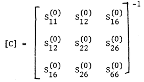 | (18) |
The transverse stresses can now be solved by substituting the in-plane stresses obtained in (16) into the last equations of (7.4) and integrating with respect to y, we then get: 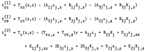 | (19) |
where Trz, TrƟ and Tr are the stress components at y = 0 and Aij , Bij , Dij , Eij are the products obtained by integration of stress strain coefficient components over the thickness coordinate. Satisfaction of boundary conditions provides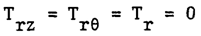 | (20) |
The following equations are expressed in terms of strains and curvatures: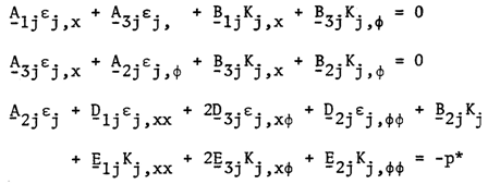 | (21) |
Where p* = p / (σλ), to non-dimensionalize where λ is total thickness (h) divide by inner radius (a), λ = h/a. The equation (21) can be expressed in terms of displacements by substituting relations (17) for strains and curvatures. This will lead to the following equations for unknown displacements vr, vƟ and vz: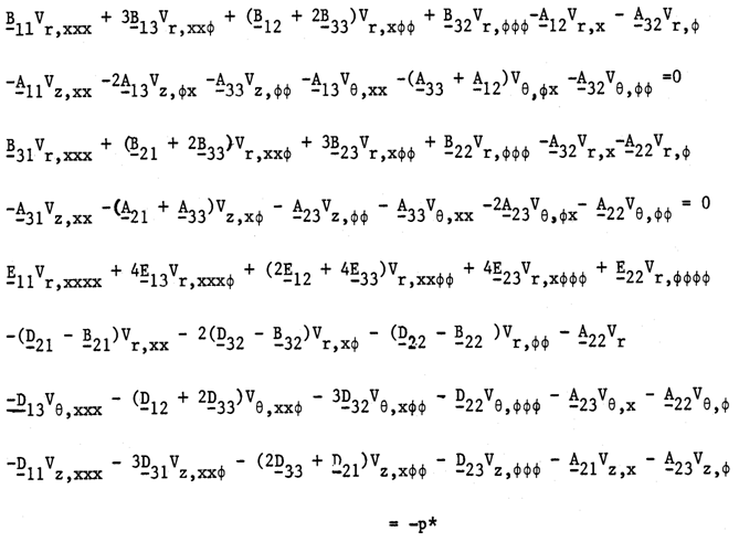 | (22) |
The above equations represent as the characteristic governing equations describing the theory of cylindrical shell of intermediate length and short longitudinal length scale and short circumferential length scale of hybrid anisotropic materials while the equations (9) represent the governing equation of the theory of intermediate length with short longitudinal length scale (ah)1/2 and long circumferential length scale (a), a being inner radius of the cylinder and h is the total thickness of shell wall. Both governing equations are similar but equation (22) is very complicated for solutions satisfying the boundary conditions. We can visualize for the axi-symmetric deformation, all the terms differentiated by variable, φ are disappeared, and thus the equation (22) reduces to equation (9). However, we are allowed to reduce it only when the shell is subject to internal pressure loading as shown in Figure (6).The internal pressure causes axi-symmetric deformation.We are not allowed to apply the simplified bending theory to the shells loaded externally and or compressed in longitudinal direction.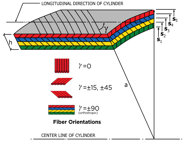 | Figure 3. A Laminated Cylindrical Shell, Material Orientation γ |
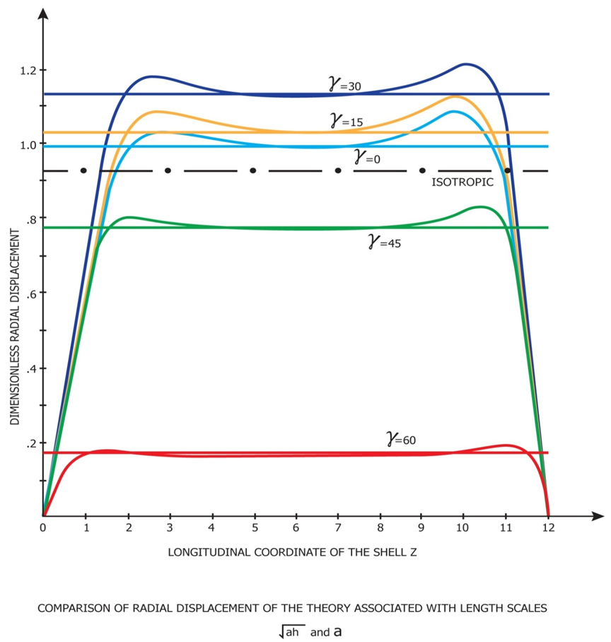 | Figure 4. Comparison of Radial Displacements of the Bending and Pure Membrane Theories |
4. Application
To demonstrate the validity of the theories developed here, we will choose a problem of a laminated circular cylindrical shell under internal pressure and edge loadings. The shell is assumed to build with boron/epoxy composite layers. Each layer is taken to be taken to be homogeneous but anisotropic with an arbitrary orientation of the elastic axes. We need not consider the restriction of the symmetry of the layering due to the non-homogeneity considered in the original development of the theory expressed earlier. Thus each layer can possess a different thickness.We assume here that the contact between layers is such that the strains are continuous function in thickness coordinate. As the  are piecewise continuous functions, the in-plane stresses are also continuous. We would expect them to be discontinuous at the juncture of layers of dissimilar materials. The transverse stresses are continuous functions of the thickness coordinate, r.Although as mentioned above the theory developed can take unlimited hybrid random layers but for an example, a four-layer symmetric angle ply configuration. For this configuration the angle of elastic axes
  is oriented at
  ,
,  ,
,  ,
,  with the shell axis and the layers are of equal thickness. Figure 3 shows a laminated Cylindrical Shell, Material Orientation γ. Figures 4 and 5 are the deformation patterns along the longitudinal axis and Figure 6 is a recommended use of the two different theories, the original Donnell-Vlasov and simplified versions.Let the shell be subjected to an internal pressure
  , an axial force per unit circumferential length
  . The axial force is taken to be applied at
  such that a moment
  is produced about the reference surface
  . We introduce dimensionless external force and moments as previously described.To demonstrate the validity of the derived theory, we have simplified loading and boundary conditions as follows:
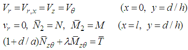 | (23) |
Here,  is the dimensionless length of the cylindrical shell.In the theories developed in the previous chapters, the distance d at which the stress resultants were defined was left arbitrary. We now choose it to be such that there exists no coupling between
  and
and  and
and  and
and  .As the loading applied at the end of the shell is axi-symmetric, all the stresses and strains are also taken to be axi-symmetric. We thus can set all the derivatives in the expressions for the stresses and strains and in the equations for the displacements equal to zero.Numerical calculations are now carried out for a shell of wall of various hybrid laminae.Each of the layers is taken to be equal thickness and thus the dimensionless distances from the bottom of the first layer are given by
 each layer of the symmetric angle ply configuration (elastic symmetry axes y are oriented at
 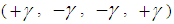 is taken to be orthotropic with engineering elastic coefficients representing those for a boron/epoxy material system,
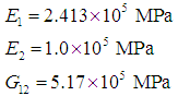 Here direction 1 signifies the direction parallel to the fibers while 2 is the transverse direction. Angles chosen were
  = 0, 15, 30, 45 and 60. Use of the transformation equations in Reference (13) then yields the mechanical properties for the different symmetric angle ply configurations.We next apply the following edge loads:
  and take
 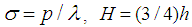 and the reference surface we take
  .Shown in Figures (4) and (5) are the variation of the dimensionless radial displacement with the actual distance along the axis for the different theories. The reference surface for the chosen configuration is given by
  . The integration constants determined from the edge conditions.It is also seen that wide variations in the magnitude of radial displacement take place with change in the cross-ply angle. The maximum displacement occurs at
  degree while the minimum displacement is at
  degree. Also shown in the Figure 5 is the patterns of near edge zone for both bending theories, One is simplified bending theory shown in the equation (9) and the other the expanded Donnell Vlasov bending theory for hybrid anisotropic materials. The results of both bending theories are identical for the case of internal pressure loading as explained earlier.In each case, the displacements increase with increase in
  up to
up to  degree and thereafter decrease.
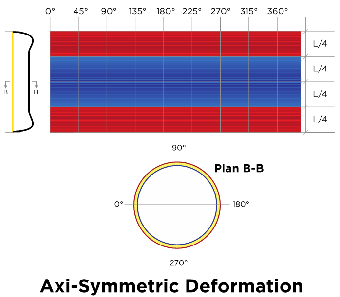 | Figure 5. Side View of Axi-symmetric Deformation |
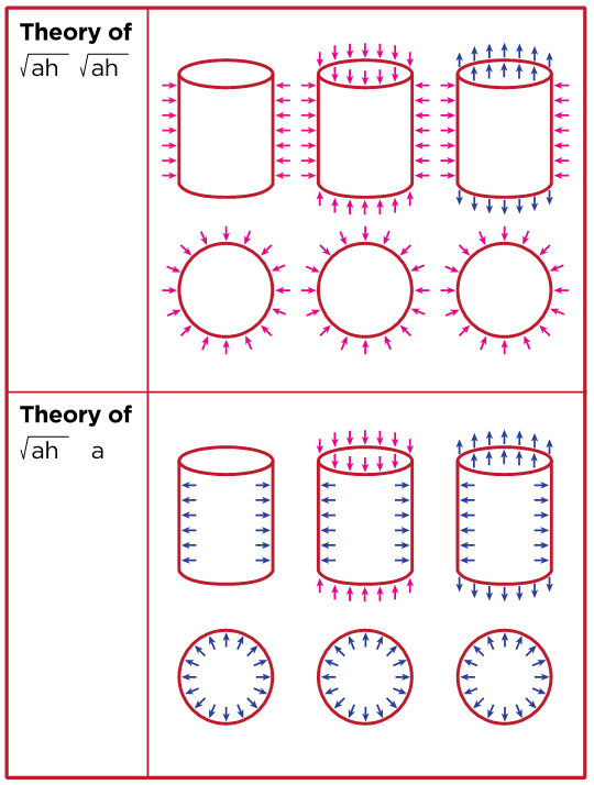 | Figure 6. Loading Combination and Corresponding Equations |
5. Conclusions
The classical Donnell-Vlasov theory for intermediate length circular cylindrical shells of isotropic materials was extended further to accommodate for the hybrid anisotropic materials. The first approximation shell theories derived by use of the method of asymptotic integration of the exact three-dimensional elasticity equations. We have introduced the characteristic effective length scales as shown in this paper, L for longitudinal, ℓ for circumferential. We choose L = (ah)1/2 and ℓ = (ah)1/2 to arrive at the equivalent Donnell-Vlasov equations and L = (ah)1/2 and ℓ = a to simplified version. Both theories are pros and cons. Recommended use for different loading conditions were shown.The analysis is valid and useful for materials which are non-homogeneous to the extent that their properties are allowed to vary with the thickness coordinate (r).Although twenty one elastic coefficients are present in the original formulation of the problem, only six are appear in the first approximation theories. The fact that these expressions can be determined is very useful when discussing the possible failure of composite structures.For design of space shuttles and other vehicles, a shell structure must be carefully designed for all possible loading conditions, extremely high negative and positive pressure and temperature, which demands further accurate shell theories. We have developed both shell theories for the purpose.However due to the fact that the equations of modified Donnell-Vlasov theory is extremely sensitive and complicated to solve for all stresses and strains of hybrid anisotropic materials under different loading conditions, we found the need and use of simplified version. The governing equations of (22) and (9) will better explain it.
ACKNOWLEDGEMENTS
The research was sponsored by Summit Partners in Menlo Park, California, USA and graciously acknowledged.
References
| [1] | Love, A.E.H, “A treatise on the mathematical theory of elasticity”, Dover Edition, New York. |
| [2] | Donnell, L.H., “Beams, Plates and Shells”, McGraw-Hill Book Company, ISBN0-07-017593. |
| [3] | Reissner, E., “The effect of transverse shear deformation on the bending of elastic plates”, J. Appl. Mech. 12, No A69-77, 1945. |
| [4] | Johnson, M.W. and Widera, O.E., “An asymptotic dynamic theory for cylindrical shells”, Studies Appl. Math. 48, 205, 1969. |
| [5] | WIDERA, O. E., “An asymptotic theory for the motion of elastic plates”, Acta mechanica 9, 54, 1970. |
| [6] | Vlasov, V.Z., “General theory of shells and it’s application in engineering”, NASA TT F-99, National Tech. Information Service. |
| [7] | Vlasov, V.S., “Basic Differential Equations in General Theory of Elastic Shells”, NACA Technical Memorandum 1241, 1951. |
| [8] | Goldenveiser, A.L., “Theory of elastic thin shells”, Pergamon Press. |
| [9] | Ting, T.C.T., “Anisotropic Elasticity”, Oxford Engineering Science Series 45, Oxford University Press. |
| [10] | Birman, V., “Extension of Vlasov’s Semi-Membrane Theory to Reinforced Composite Shells”, J. Appl Mech 59 (2), 464-464. |
| [11] | Reddy, J.N., “Mechanics of Laminated Composite Plates and Shells”, 2nd Edition, CRC Press. |
| [12] | Chung, S.W. and Park, S.M., “A Shell Theory of Hybrid Anisotropic Materials”, International Journal of Composite Materials, Volume 6, Number1, February 2016. |
| [13] | Chung, S.W. and Hong, S.G., “Pseudo Membrane Shell Theory of Hybrid Anisotropic Materials”, Journal of Composite Structures, Volume 160, Number1, January 2017. |
| [14] | ASME Boiler Code - Boiler & Pressure Vessel Code, 2015. |
| [15] | ACI 318-11: Building Code Requirements for Structural Concrete and Commentary. |
| [16] | Axelred, E.L., “Theory of Flexible Shells”, North-Holland Series in Applied Mathematics and Mechanics, ISBN 0-444-87954-4(US). |
| [17] | Blaauwendraad, J and Hoefakker, J.H., “Structural Shell Analysis’, Springer, ISBN 978-94-007-6700-3. |
| [18] | Calladine, C.R., “Theory of Shell Structures”, ISBN 0 521 23835 8, Cambridge University Press. |
| [19] | Batdorf et al, S.B., “A simplified Method of Elastic-stability Analysis for Thin Cylindrical Shells”, NACA Technical Notes No. 1341 through 1345. |
| [20] | Ambartsumian, S.A., “Fragments of the Theory of Anisotropic Shells”, World Scientific Publishing Co., ISSN 0218-0235. |
| [21] | Vinson, J.R., “The Behavior of Shells Composed of Isotropic and Composite Materials”, Kluwer Academic Publishers, ISBN 0-7923-2113-8. |

 Abstract
 Reference
 Full-Text PDF
 Full-text HTML