Daisy Pinheiro, Orlando Longo, Gabriel Nascimento, Gilberto Couri
Department of Civil Engineering, Fluminense Federal University, Niterói, Brazil
Correspondence to: Daisy Pinheiro, Department of Civil Engineering, Fluminense Federal University, Niterói, Brazil.
| Email: |  |
Copyright © 2017 Scientific & Academic Publishing. All Rights Reserved.
This work is licensed under the Creative Commons Attribution International License (CC BY).
http://creativecommons.org/licenses/by/4.0/

Abstract
This work deals with the recovery of small slab with reinforcement in composites of carbon fiber. Are demonstrated the advantages and the disadvantages of the traditional methods of structural and recovery method with composite carbon fiber on a small slab with the goal of demonstrating the viability of the use of CFCs in small structures. For this, calculations were made by traditional method and computational method through finite elements. The calculations in the software ANSYS Mechanical 17 allowed a more precise analysis of the structure, considering the stress of slab, bores geometry, steel reinforcements, CFRP, concrete and non-linear behavior. Compared to the traditional method, the tool promotes greater reliability, where the slab reinforced with CFRP reached a maximum compression value of 11.6 Mpa.
Keywords:
Carbon Fibre Composites, Structures Recovery, Finite Element Method, Small Structure
Cite this paper: Daisy Pinheiro, Orlando Longo, Gabriel Nascimento, Gilberto Couri, Use of Composite Materials in Carbon Fiber for the Recovery of Small Slab – Calculation by Analytical and Computational Methods, International Journal of Composite Materials, Vol. 7 No. 1, 2017, pp. 1-7. doi: 10.5923/j.cmaterials.20170701.01.
1. Introduction
The conventional backup systems of structures in recent decades have been replaced with carbon fiber composite materials given to proven strength and rigidity characteristics besides being non-corrosive material, low weight and high performance.Carbon fibers are the result of heat treatment of polymer fibers such as poliacrilonitril, can be based on petroleum-derived or coal tar and also through rayon fibres [1].The high strength and high modulus of elasticity, in addition to your low weight, maximum of 1,9 g/cm³ and high corrosion resistance, extends its use in several areas of engineering, encouraged by other indispensable features in recovery structures, as the malleability of composites in tissue form, versatility of application, durability, fire resistance, easy maintenance, good behavior to fatigue, in Figure 1 we present a comparison of the resistance to deformation of some types of materials.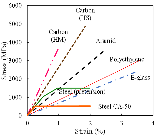 | Figure 1. Stress-strain plot of fibers and metals. Adapted from Berber (2003) |
2. Composite Systems and Sustainability
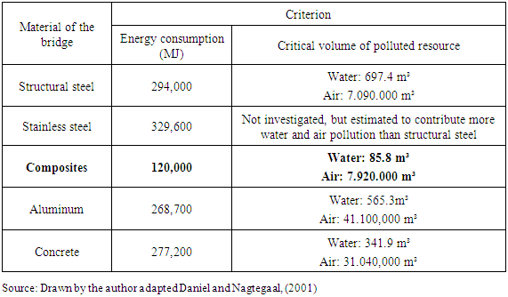
The application of fibre-reinforced plastics (FRP) in reinforced concrete structures, alternatively the application systems in steel, appeared in the middle of this century [2].With regard to sustainability, the matrix and fibers manufacturing of composites, are the target of concern because they are polymers derived from crude oil, natural gas, chlorine [3].Considering the energy resources as a reference, the fiber composites in built environment, are questionable, however other advantages must be considered: low thermal conductivity, low use of inputs in reinforcement applications, resulting in efficient production, with a lesser degree of energy production. Its high durability, requires less maintenance, soon greatest gain with the practice of Assessing of The Cycle in Sustainability, where the total cost should consider future maintenance and production losses [4].The amount of water more used for the production of materials used in civil construction, is an important factor for the classification of sustainability.In the table below, comparison the volume of water for the various materials, showing the composites as the best result.Table 1. Comparison of the environmental impact of five structural materials
 |
| |
|
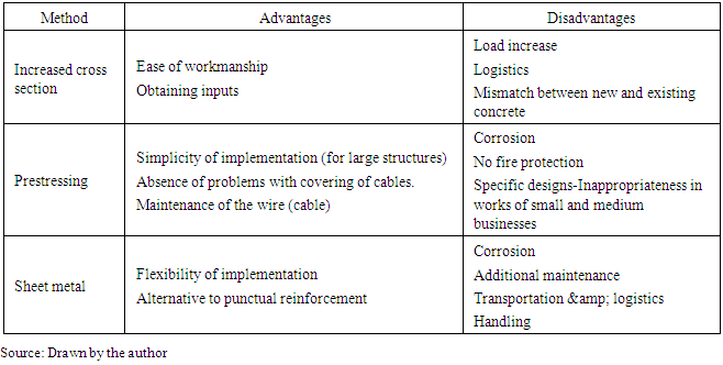
Receive in their research, the materials that compete with the composites require greater use of energy and raw materials, by requiring a greater number of maintenance, with machines and equipment [5].The use of carbon fiber composites in bridges, viaducts, have on average a lifespan three times higher than the concrete structures [6].The actions for the rehabilitation of structures are a complex branch of engineering, whose impact is becoming ever greater, as the demand for repairs, backup and maintenance, increases every day. Efficient rehabilitation strategies that satisfy a multitude of design and implementation constraints represent the major challenge to be faced. In most cases, the option for the rehabilitation of a structure represents the best allocation of scarce resources available [7].In Brazil, due to the absence of technical standards, specifications and structural recovery technologies, their use is limited, preventing use in recoveries of smaller structures, which would provide higher quality, reduced work period, resulting in a lower cost [8].The choice of recovery method of the structure will depend upon the peculiarities of each situation and factors, among which: construction type and age of the structure, level of intervention, cost, logistics, design and runtime work [9].The more traditional techniques are: the reinforcement of the structure with the treatment of hardware and increased cross section; the stressing and strengthening with sheet metal (steel). These techniques although very widespread, it doesn't always result in great choice.The table 2 compares the advantages and disadvantages of traditional recovery types of structures.Table 2. Advantages and disadvantages of Traditional types of Structures
 |
| |
|
These methods though still widely used in construction, demand a more thorough planning and tracking, a more detailed execution inspection, increased risk of accidents, runtime error, rework, waste of materials, adequate space built and occupied and increased duration of the works. All these costs must be considered in choosing the best method of recovery.The choice, therefore, of these techniques should be based on the following considerations: types of pathology, location, accessibility, labor, cost, size and typology of the structure, maintainability.This work aims to demonstrate the application of carbon fiber composites in structure of small, as recovery alternative better compared to traditional methods. Two basic parameters will be analyzed in the choice of methods: technical and cost. Below, case study.
3. Case Study
Is presented a case study of a small slab, flat area, showing cracks and loose parts by several interventions on the grounds of the apartment immediately above.Were developed an analytical model and a finite elements. A comparison of the results was made while giving the choice of method, in relation to the cost benefit.Finally will be presented the costs of two methods, taking into account the materials, lead time, logistics and labor.
3.1. Description of the Case
Apartment bathroom slab, with dimensions of 1,90 x 2.00 m. The building has approximately 30 years old, and this compromises the compatibility between old and new materials. The structure is in reinforced concrete. The slab is supported in perimeter reinforced concrete beams with 4.20 m and free span of 3.10 in another sense. All the slabs and the passageways and rooms bathrooms are on the same level. Sewage facilities, cross slabs from the apartments.The bathroom slab showed cracks and breakdowns of part of the structure due to various interventions and reforms in the flat immediately above, with risk of collapse of part of the slab, endangering the lives of the residents of the apartment below.After analysis, it was indicated the recovery of structure, because there is risk of collapse of part of the slab.At first they were considered two alternatives: the recovery of the structure with the implementation of the existing spare slab and reinforcement with hardware and new concrete crosses, which in both cases would require time, hampered by the little will and existence of sewer pipes; materials and equipment logistics, high production cost, inconvenience to the owners, residents of both apartments.From these actors, the option of strengthening with carbon fiber composite, came to be considered Figure 2 shows the plant with the corresponding beams.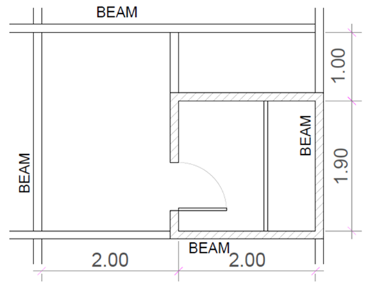 | Figure 2. Schematic plan |
In this case study, we used the real carbon fiber composites as reinforcement of slab structure of bathroom of apartment, alternatively in order to replace other conventional invasive forms. The slab was reinforced with parameters calculation and analysis, with comparative method between structural reinforcement in concrete and steel reinforcement in CFC (carbon fiber composite). The execution with the composite-blades-accompanied study on interference function of existing sewer ducts in slab. Carbon fiber blades will hold the transmission of forces and should overtake safely the minimum value of armor necessary at any point and direction. This criterion does not made economically strengthening solution using carbon fiber composites, since in this particular case, was the difficulty of limiting implementation (limited access, desktop tiny, logistics, work time). The laminate was used for presenting best option of reinforcement in small area and by its applicability.
4. Structural Analysis
The slab has undergone several operations, some old already, others recent. In these interventions, especially in this last in progress, were not taken the care required for the structural preservation of the slab with the necessary safety and established the standards of reinforced concrete [10], as seen in figures 3 and 4 which have irregular cuts of concrete.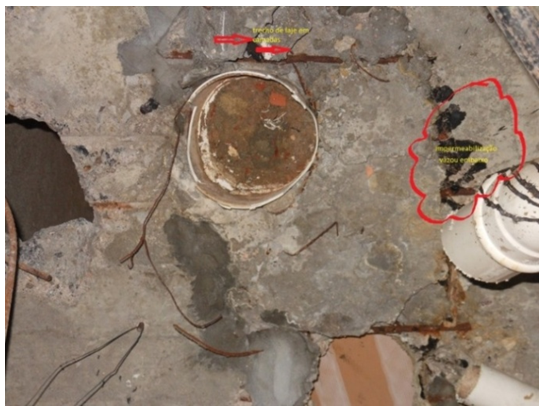 | Figure 3. Top floor - slab ceiling lower-cut steel bars |
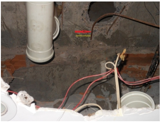 | Figure 4. Top floor - slab ceiling lower - cut steel bars |
In a concrete sector appears in layers, with visible danger of falling of the bottom layer. Several structural steel bars of reinforced concrete were cut and were not replaced.The slab thickness, measured in one of the holes is 7 cm, by apparent irregularities it is assumed that the original slab thickness was 10 cm.Not having the original structural design drawings, the assumptions that appeared as more reasonable and safe.
4.1. Analytical Calculation
4.1.1. Analysis of Damaged Slab
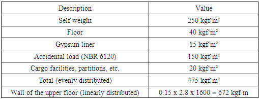
In table 3 are the calculation of the loads.Table 3. Applied loads
 |
| |
|
By the traditional method of calculating efforts in slabs and on the basis of table 4 loads, gets a moment Mx = 440 m.kgf (vector parallel to the shorter side) and My = 340 m.kgf (vector parallel to the longest side). On the basis of the tables for the calculation of Barês slabs and Hahn, assuming a Poisson coefficient ν = 0.15 and simple edge support, armor required is presented in the table below.Table 4. Required reinforcement by analytical calculation
 |
| |
|
4.1.2. Analysis of Slab with CFRP Reinforcement
Comparative calculation of equivalent calculation methods of 6.3 mm (31.16 mm²) rebar in carbon fiber laminate to 165 Gpa.Calculation Of The Force Mobilized In Armor (load transfer = 0,2%):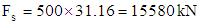 | (1) |
Calculation of the equivalent section of carbon fiber: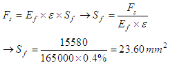 | (2) |
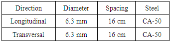
Considering a laminate 50 x 1.4 mm have a section of 70 mm² (or 4.45 times the force that mobilizes a rebar of 6.3 mm).For the area of the slab which is 4, 00 m x 2, 50 m and with 16 cm spacing between rods, we have 24 rods on larger and 15 rods in smaller dimension.The six 50 x 1.4 mm laminates to 165 Gpa applied on larger slab direction equals 26 6.3 mm Rebar and toward less were placed 2 cross laminated equivalent to 9 6.3 mm rebar. The need is 15 rods and will be compensated with 2 layers of 25 cm wide of carbon fiber laminate of 230 Gpa and 300 g/m² and 0.165 mm thickness.The carbon fiber fabric will be applied in the region more handicapped where concentration of disabilities and in order to cross in both directions. The criterion is to disregard the existing armor and put all new armor, isolation, and calculations of safety studies.There is a need for a hardware of 6.3 mm bar 1 every 16 cm in both directions, in other words, just under 2 cm²/m in both directions.
4.2. Finite Element Analysis
The structure was also verified by finite element analysis, with ANSYS Mechanical v17 software. With this computational tool, based on finite element method, it is possible to perform a very detailed and precise calculation, considering hole geometries, steel reinforcements, CFRP, concrete and its cracking at tension zone (non-linear behavior).
4.2.1. Model geometry
The slab geometry (Figure 5) was defined based on measured dimensions (Figure 2) and observed holes (Figures 3 and 4). | Figure 5. Steel reinforcement grid and hole geometries |
Due to the lack of information about the original project, the diameters and spacing between steel bars were assumed as the same calculated analytically (Table 5). As a conservative assumption, both directions were considered in the lower grid. For the upper reinforcement grid, however, only longitudinal steel bars were implemented. In addition, in the holes region, the bars were removed (Figure 5).The CFRP ribbons had 50 mm by 1.4 mm (width and thickness). It was positioned at the lower surface, according to the installed reinforcement, with six ribbons in longitudinal direction and two in transversal direction (Figure 6). | Figure 6. CFRP positioning |
4.2.2. Domain Discretization
Different element types discretized the domain, according to the most efficient choice that represents properly the mechanical behavior of each component in the structure. The element type SOLID186, which is a tridimensional solid element with quadratic shape functions, represented the concrete. The linear beam element type BEAM188 constituted the steel reinforcement bars.Horizontal divisions imposed the creation of nodes at the intersection between steel bars grid and concrete in order to ensure a good connection between those different components. For the same reason, lower and upper steel grid planes divided vertically the domain in three element layers (Figure 7). Those definitions resulted in a total of 16,050 nodes and 4,305 elements.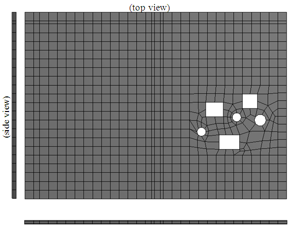 | Figure 7. Domain discretization |
The CONTA175 and TARGE170 element types connected bar and solid elements, respectively, set to the option MPC (Multipoint Constrain). The same element pair connected CRFP to slab configured with the option “bonded”.The CFRP ribbons was divided into SHELL181 elements (Figure 8), which is a shell element with linear shape functions. It was present only in the reinforced model, where also the slab holes was filled with concrete.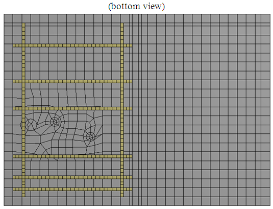 | Figure 8. CFRP discretization (reinforced model) |
4.2.3. Applied Loads and Boundary Conditions
An uniform pressure defined the loading along the slab surface with the value presented in Table 4. The linear load value of central wall (672 kgf/m²) was divided by the wall thickness (0.15 m) and distributed along this wall footprint (vertical projection).The applied boundary conditions restrained the right edge (front view) against translation in vertical direction (z) and the left edge against translation in x and z (Figure 9). An analogous boundary condition restrained the front and back edges (side view).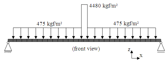 | Figure 9. Applied loads and boundary conditions |
In order to compensate the loss of area due to holes, a larger value of distributed load was calculated and applied to the surface between holes.
4.2.4. Materials Definitions and Settings
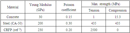
Concrete, steel and CRFP were the materials defined. In order to consider cracking over the tensioned zone of concrete and allow a proper loading transfer to steel bars and CRFP reinforcements, the Drucker-Prager model was chosen to define the concrete material. The values used for Young Modulus, Poisson coefficient and maximum strength of each material are presented in Table 5, according to their specification or typical values.Table 5. Material properties
 |
| |
|
Due to the slab slenderness and nonlinear behavior of contact between different components, the “large deflection” option was activated. Four steps divided the ramped loading application in order to achieve a better convergence.Other settings not mentioned here was kept as the software default.
4.2.5. Results
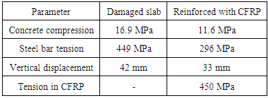
There are two different situations for the model: initially damaged and reinforced with CFRP. In the first one, according to the previous description, there are holes in the slab and no steel bar reinforcement at the damaged zone. In the second situation, the holes was filled up with concrete and CFRP ribbons reinforced the slab to compensate the loss of steel bars.Results are focused in the compression stress on concrete, tension stress on steel bars and CFRP ribbons. The calculated values are compared to the allowable limits. Vertical displacement of slab is also presented to verify the effect of CFRP reinforcement on the structure behavior.For the damaged slab, as showed in Figure 10a, the minimal principal stress (maximum compression) calculated in concrete was 16.9 MPa, which is beyond the allowed limit (15.3 MPa). For the slab reinforced with CFRP, the calculated value decreased to 11.6 MPa (Figure 10b).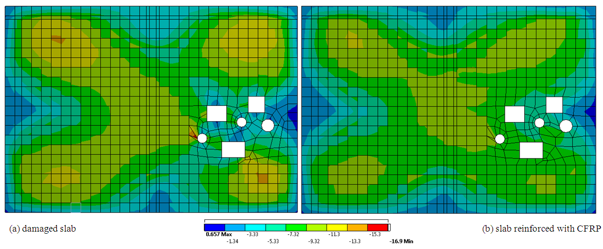 | Figure 10. Minimal principal stress in concrete (MPa) |
It was observed also a better stress uniformity in the holes side (right), reducing the higher values and increasing the small ones.The maximum principal stress in concrete was not considered, because it was assumed that tension values larger than 1 MPa cause crack and consequent load transfer to the reinforcement (steel bar and/or CFRP). The maximum stress value calculated in steel bars for the damaged slab was 449 MPa, located next to the holes zone, as expected (Figure 11a). This value is greater than the allowable limit for the steel (435 MPa) presented in Table 5. This over tension, which is calculated for the loading values in Table 3, would cause yielding and probably bring the slab to collapse.With the CFRP reinforcement, the maximum calculated stress in steel bars was 296 MPa (Figure 11b), which means a decrease of 35%. Stress values from the holes side (right) became smaller than those from the other side (left), indicating the influence of CFRP ribbons.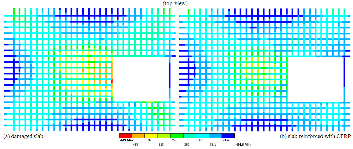 | Figure 11. Tension stress in steel bars of lower grid (Mpa) |
The maximum calculated stress in CFRP was 450 MPa (Figure 12), located in a transversal ribbon and close to the slab center. This value is far away from the allowable limit (2500 MPa). In the other ribbons, stresses are smaller than the half of calculated maximum. This indicate that the ribbons arrangement could be more efficient.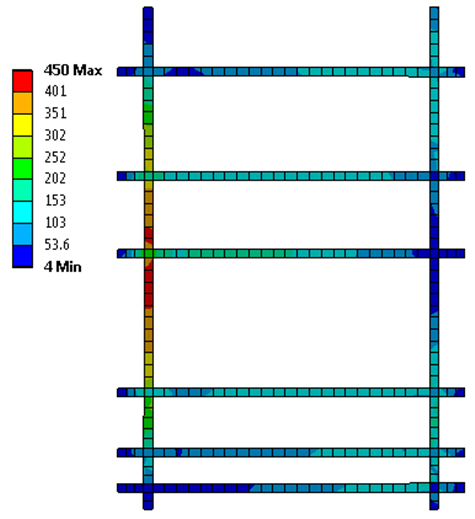 | Figure 12. Stress in CFRP (MPa) |
Regarding the vertical displacement, the maximum value calculated was 42 mm for the damaged slab and 33 mm for the slab reinforced with CFRP. Table 6. Comparative values
 |
| |
|
According to the previous results, a structural maintenance was definitively necessary and the installed CFRP reinforcement was sufficient to ensure the structural reliability.
5. Conclusions
From a technical point of view, the option for reinforcement in CFC tested positive, albeit in small slab. The use of the calculation by the analytical method provided limited results to efforts on the slab, ceding strenght on armor to compensate with CFC, although with the use of computational tool based on finite element method, it was possible to make a precise calculation, considering bores geometry, steel reinforcements, CFRP, concrete and non-linear behavior. It is concluded that, even with the settings for the placement of laminates on the slab, the CFRP reinforcement installed was sufficient to ensure structural reliability, where was on slab damaged a maximum compression in concrete of 16.9 MPa, the value calculated for slab reinforced with CFRP decreased to 11.6 Mpa, higher than the allowed limit of 15.3 Mpa.
References
| [1] | Paula Machado, Ari – Reforço de Estruturas de Concreto com Fibras de Carbono – Pini. 2002. |
| [2] | Rubinsky, Ivan A., and Andrew Rubinsky. "A preliminary investigation of the use of fibre-glass for prestressed concrete."Magazine of Concrete Research6.17 (1954): 71-78. |
| [3] | Gerdeen, James C., and Ronald AL Rorrer. Engineering design with polymers and composites. Vol. 30. CRC Press, 2011. |
| [4] | Hollaway, Leonard C., and Mike Leeming, eds. Strengthening of reinforced concrete structures: Using externally-bonded FRP composites in structural and civil engineering. Elsevier, 1999. |
| [5] | Daniel RA, Nagtegaal G (2001) Pedestrian bridge of pultruded sections as result of ecological design. In: Proceedings of the EPTA seminar, Roermond, Oct 2001. |
| [6] | Hollaway LC (2010) A review of the present and future utilization of FRP composites in the civil infrastructure with reference to their important in-service properties. Constr Build Mater24:2419–2445 |
| [7] | Beber, A. J. Avaliação do desempenho de vigas de concreto armado reforçadas com lâminas de fibra de carbono. Porto Alegre: CPGEC/UFRGS, 1999. Dissertação de Mestrado em Engenharia. |
| [8] | Norma Técnica Americana ACI-440-2R:02(2008). |
| [9] | Robery, P.; Innes, C. Carbon fibre strengthening of concrete structures. In: International Conference on structural Faults and Repair, 7., 1997, Edinburgh. Proceedings…Edinburgh: Engineering Technics Press, 1997. 3v. v.1, p. 197-208. |
| [10] | ABNT –NBR 6118:2014 - Projeto de Estruturas de Concreto – Procedimento. |

 Abstract
 Reference
 Full-Text PDF
 Full-text HTML