-
Paper Information
- Paper Submission
-
Journal Information
- About This Journal
- Editorial Board
- Current Issue
- Archive
- Author Guidelines
- Contact Us
International Journal of Composite Materials
p-ISSN: 2166-479X e-ISSN: 2166-4919
2016; 6(6): 183-195
doi:10.5923/j.cmaterials.20160606.03

Prediction of Ultimate Load at the CFRP-Concrete Interface under Pure Shear Mode
 Abstract
 Reference
 Full-Text PDF
 Full-text HTML
Mohsen A. Issa1, Momenur Rahman2, Rajai Alrousan3
1Department of Civil and Materials Engineering, University of Illinois at Chicago, Chicago, USA
2University of Illinois at Chicago, Chicago, USA
3Department of Civil Engineering, Jordan University of Science and Technology, Irbid, Jordan
Correspondence to: Mohsen A. Issa, Department of Civil and Materials Engineering, University of Illinois at Chicago, Chicago, USA.
| Email: |  |
Copyright © 2016 Scientific & Academic Publishing. All Rights Reserved.
This work is licensed under the Creative Commons Attribution International License (CC BY).
http://creativecommons.org/licenses/by/4.0/

The bond strength characteristics between Carbon Fiber Reinforced Polymer (CFRP) and concrete were investigated by conducting double face shear type pullout test. A simplified experimental setup was designed for the test to eliminate the eccentricity of active load across the bond interface. The objective of the study is to determine the ultimate bond strength and corresponding slip of CFRP-concrete interface using maximum bond stress (τmax). The effect of the concrete compressive strength (f 'c) and CFRP bond width (bf) were considered as key parameters. The results indicated that the ultimate load (Pu) increased with the increase in f 'c and bf. On the other hand,the slip (so) at τmax increased as a result of increasing concrete f 'c and decreased with increasing bf. Moreover, the failure mode was more brittle with higher concrete f 'c and/or smaller CFRP bf. An analytical model is proposed to predict the ultimate pullout load (Pu) and slip (so) at ultimate load. The proposed model provided a good prediction for Pu, τmax, and so for the bond between the CFRP and concrete.
Keywords: CFRP, Concrete, Bond stress, Ultimate bond capacity, CFRP-concrete interface
Cite this paper: Mohsen A. Issa, Momenur Rahman, Rajai Alrousan, Prediction of Ultimate Load at the CFRP-Concrete Interface under Pure Shear Mode, International Journal of Composite Materials, Vol. 6 No. 6, 2016, pp. 183-195. doi: 10.5923/j.cmaterials.20160606.03.
Article Outline
1. Introduction
- Externally bonded Fiber Reinforced Polymer (FRP) plates or sheets have been widely used to retrofit and rehabilitate deteriorated concrete structures. These materials provide several advantages attributed to their light weight, high strength characteristics, and ease of installation. The design of FRP plates or sheets is controlled by the bond characteristics between the FRP and concrete substrate [1, 2]. Plenty of research was carried out in the past decade to evaluate the bond stress-slip behavior at the FRP-concrete interface both experimentally and analytically. Several prediction models were developed; however, a unified simple formula is desired to estimate the pullout load or the anchorage area for strengthening or retrofitting of RC structures with CFRP. The paper presents an experimental investigation to evaluate the ultimate bond strength between CFRP laminates and concrete. The CFRP laminates were adhered on both faces of the concrete prism using epoxy. Previous studies measured the bond stress and slip at different levels using strain gauges and/or Linear Variable Displacement Transducers (LVDTs) in order to determine the effective bond length (Le) and the maximum bond strength (τmax) at the FRP concrete interface. The test was simplified by using a single LVDT on each side of the CFRP-concrete interface. The study took into account of different bond configurations and concrete strength. In addition, an analytical model was developed to predict the test results. The analytical model can be used to determine the bond area required to resist a given load for strengthening RC structural members with externally bonded CFRP sheet.
2. Background
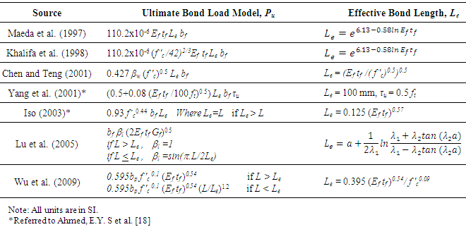
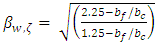
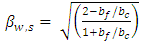
- Chen and Teng [3] investigated the anchorage strength properties of both FRP-to-concrete and steel plate-to-concrete bonded joints. They reviewed and assessed existing anchorage strength models using experimental data collected from literature and proposed a new design model based on existing experimental observations. Lu et al. [4] proposed three different models to predict the strength characteristics and bond slip between FRP and concrete. They collected experimental data from the literature and observed that most of the studies did not consider enough parameters to capture the bond-slip behavior. Moreover, they observed some scattering in the experimental results for several studies [5-8] in their database [4]. The scattering was detected in the trend of the ultimate load (Pu) between specimens with different configurations as well as between identical specimens. This scattering and inconsistency in the test results can affect the accuracy of the prediction model [4]. Therefore, it is essential to investigate all the factors influencing the bond properties including the testing setup and equipment when testing the bond slip behavior between FRP and concrete.Dai et al. [9] conducted a single lap pullout test using 26 specimens to capture the bond stress-slip behavior at the FRP-concrete interface using different FRP types (CFRP, Aramid FRP, Glass FRP) and three different types of adhesives. They developed a nonlinear model based on interfacial fracture energy (Gf) and interfacial ductility index. McSweeney and Lopez [10] investigated the bond-slip behavior at the CFRP-concrete interface using different CFRP bond width (bf), thickness (tf), bond lengths (L), and varying concrete f 'c. They observed that the CFRP bf and tf and the concrete f 'c significantly affected the Pu while the FRP L didn’t show any notable effect. Fawzia et al. [11] concluded that the FRP tf has significant effect on Pu, while L exceeding the effective bond length (Le) didn’t show any notable effect. Ko et al. [12] reported that concrete f 'c, FRP stiffness, and Gf are the main contributing factors for the bond stress-slip behavior. They observed that the adhesive’s strength and stiffness have no significant effect on the bond-slip behavior.Studies reported in literature considered the FRP L effect on Pu as insignificant when it exceeds Le. Maeda et al. [13] reported that the Pu for CFRP strips did not increase for any L above 100 mm. Nakaba et al. [14] reported that the bond failure by FRP delamination occurs when L is less than 100 mm, while failure by FRP rupture takes place when the anchorage length is relatively large (greater than 300 mm). Several studies [3, 4, 13-18] proposed empirical formulas to estimate the Le. Table 1 summarizes the proposed Le models obtained from the literature.
|
3. Research Objective and Significance
- Two parameters were considered for investigation: (1) effect of CFRP bond width (bf), and (2) effect of concrete ultimate compressive strength (f 'c) on the bond strength behavior at the CFRP-concrete interface. This study has the following research significances:1. The study developed a simple experimental setup that eliminates the acting load’s eccentricity across the CFRP-concrete bond interface.2. Performed a parametric study with ample number (thirty) of test specimens considering the major aforementioned key parameters, so that the characteristics of CFRP-concrete bond interface can be captured.3. A prediction model to calculate ultimate bond strength and corresponding slip model was developed based on regression analysis of experimental test results. The proposed model is simple and capable of predicting the ultimate bond strength, and the slip in terms of maximum bond stress.
4. Experimental Program
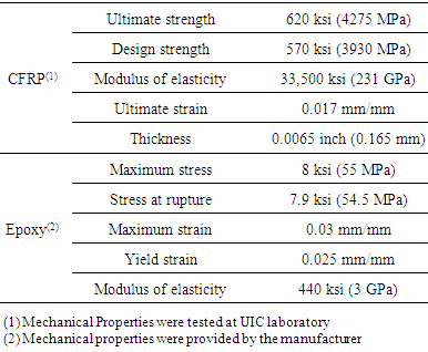
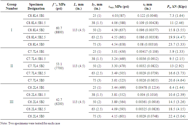
- Test Specimens The mechanical properties of CFRP sheets and the epoxy bonding agent (epoxy resin) are summarized in Table 2. Rectangular concrete prism of 150 × 150 × 525 mm (6 × 6 × 21 in.) were cast and cured in the lab and then were cut into small prisms using a diamond blade saw-cut according to the desired length required for testing. Fig. 1 shows the bond-slip test configuration for CFRP sheets and concrete for all the specimens. The CFRP sheets were adhered to the concrete specimens after being moisture cured for 28 days. The details of the tested specimens are shown in Table 3.
|
 | Table 3. Details of the Bond Slip Specimens |
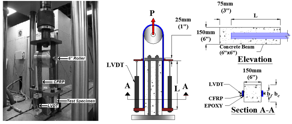 | Figure 1. Typical layout of bond slip test setup and specimen |
5. Experimental Results and Discussion
- Load and displacement data were collected for each specimen. The slip (s), which is the relative displacement between concrete and the CFRP strip, was measured directly from the LVDTs. The bond stress (τ) was calculated by dividing the respective pullout load (P) by the area of the bonded CFRP strip to concrete (Ab = L × bf). The P on each strip was taken as half of the overall load applied on the specimen. Max bond strength (τmax) is taken as the ultimate load (Pu) divided by Ab i.e., (Pu/Ab). The τmax represents the maximum value of bond stress along the bond length and the corresponding slip (so) is measured from the LVDTs. Mode of FailureThe failure of the specimens was brittle and followed by interfacial debonding of the CFRP strips from the concrete surface by removing a thin layer of concrete. For a given boundary conditions, all the tested specimens exhibited similar failure mode (i.e., interface debonding) irrespective of the concrete f 'c, and bf. Typical failure was initiated by making a peeling off sound during the early to middle stage of loading signifying the starting point of the interfacial bond delamination. When the ultimate load was approached, the CFRP strip debonded from the concrete surface following a loud noise due to the sudden release of energy. After debonding, the specimens experienced a significant loss in resistance and the load dropped gradually. Fig. 2 shows the modes of failures of specimens with different f 'c and CFRP bf, respectively. The interface debonding of CFRP strip from the concrete surface was expected, since the bond interface of CFRP to concrete was subjected to pure shear mode during the load application. It is noteworthy to mention that the test setup for this study was designed to prevent any failure initiating by either splitting or cracking at the leading edge of the concrete prism.
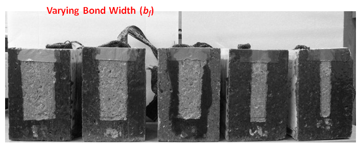 | Figure 2. Mode of failure in specimens |
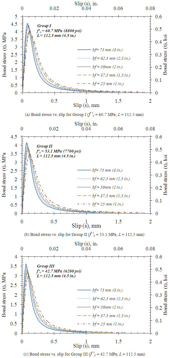 | Figure 3. Bond vs. Slip behavior of all the tested specimens |
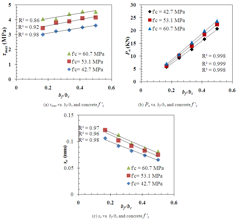 | Figure 4. Effect of bf/bc and concrete f 'c on the maximum bond stress (τmax) |
 The Pu increase due to concrete f 'c was observed less significant compared to other studies (Lu et al. [4] database). These studies observed that the Pu will increase as a result of increasing f 'c. Their specimens failed by either splitting of the concrete block or by stripping out a concrete chunk at the leading edge of the FRP concrete interface however, the present study observed interface deboning between CFRP and concrete surface.
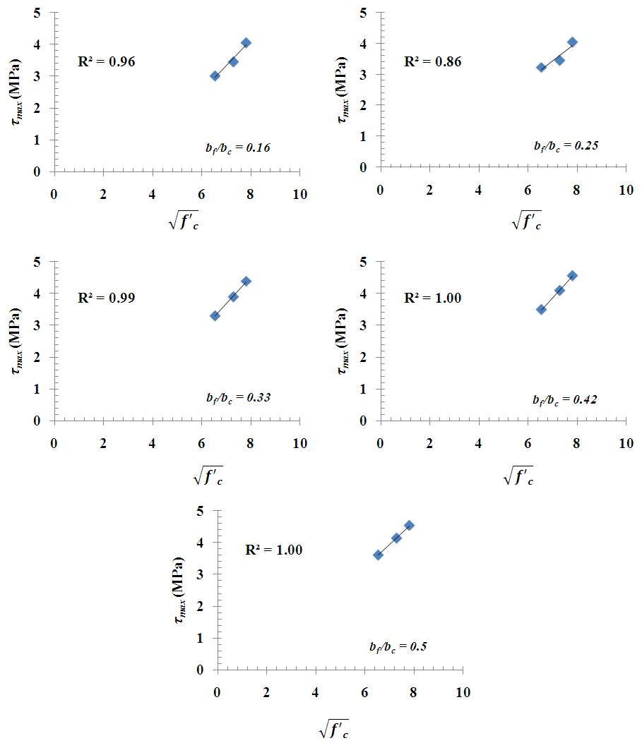 | Figure 5. Effect of concrete f 'c on the maximum bond stress (τmax) |
 | Figure 6. Effect of concrete f 'c on the slip at maximum bond stress (so) |
6. Development and Validation of Prediction Model
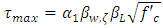
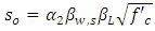
- Development of Prediction Model for CFRP-Concrete BondA prediction model for Pu and so was proposed based on the regression analysis of the results obtained from the 30 pullout test specimens. The proposed prediction model is an enhancement of ultimate load prediction model originally proposed by Chen and Teng [3]. The model is based on prediction of effective CFRP bond area. The effective bond area is defined as Ab = Le x bf; where Le is the effective bond length. According to studies in literatures it was observed that τmax is proportional to tensile strength of concrete which is a function of
 The data for τmax for every specimen and corresponding
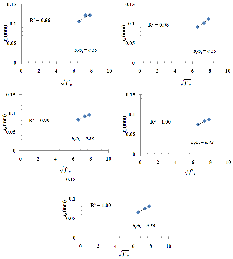
  of that specimen were shown in Fig 7(a). Inspection of Fig. 7(a) revealed that there is a strong linear correlation (R2 = 0.99) between τmax and
  Similarly, so and the corresponding
  for all specimen were shown in Fig. 7 (b). Fig. 7 revealed that the both τmax and so are affected by the change of
  The proposed equations for τmax and so are shown in Eqs. (1) and (2):
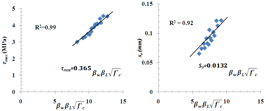 | Figure 7. Relationship between maximum bond strength (τmax) and slip at τmax (so) with f 'c ratio |
 | (1) |
 | (2) |
 | (3a) |
 | (3b) |
 | (3c) |
 (see Fig. 7(a)). Similarly, α2 was found from the relation between the normalized slip at τmax (so) and
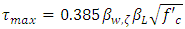
  (see Fig. 7(b)). Based on the regression analysis of experimental results, the values of α1 and α2 are 0.385, and 0.0132, respectively.Once the τmax and so are calculated, the ultimate load Pu can be estimated by using Eq. (4)
 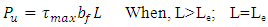 | (4) |
 | (5) |
 | (6) |
 | (7) |
 | (8) |
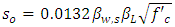
 | Figure 8. Proposed model and other research models for Pu vs. Experimental Pu |
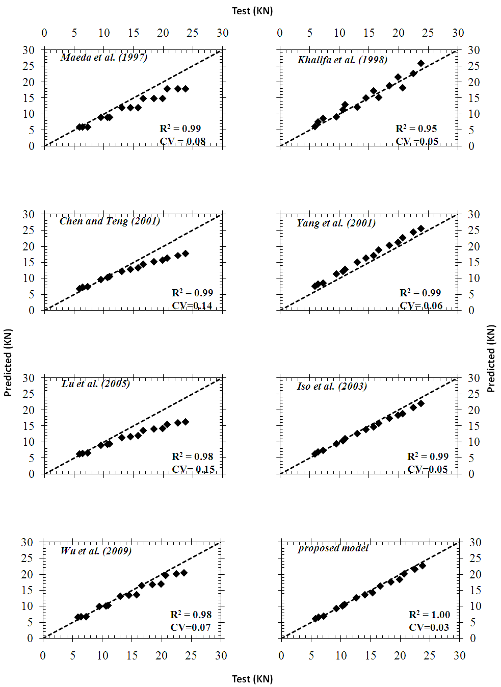
 | Figure 9. Validation of proposed model (Pu) with experimental Pu from other studies |
7. Summary and Conclusions
- The experimental study was conducted to investigate the bond strength characteristics at the CFRP-concrete bond interface. The parameters considered were CFRP bond width (bf), and the concrete compressive strengths (f 'c). A specially designed experimental testing setup using a double face shear type pullout test was implemented. The testing setup was capable of eliminating the eccentricity of active load, and ensure a pure shear failure across the CFRP-concrete bond interface. An analytical model was developed based on Chen and Teng [3] model to assess the maximum bond strength (τmax), slip at max stress (so). The following conclusions can be drawn:1. The test results revealed that for a given boundary conditions all the tested specimens exhibited similar failure mode (i.e., interface debonding) irrespective of the concrete f 'c and CFRP bf. The failure of the specimens was brittle and followed by interfacial debonding of the CFRP strips from the concrete surface by removing a thin layer of concrete. 2. CFRP bf has significant effect Pu. The increase in CFRP bf increases the Pu. The CFRP strips with wider bf increased the τmax and reduced the so. The τmax increase was observed to be influenced by the bf /bc ratio. 3. The higher the concrete f 'c the higher the τmax and so. However, the concrete f 'c effect was less pronounced on Pu.4. The experimental Pu was observed to have good fit with the existing models for specimens with variable CFRP bf and f 'c. 5. The proposed model was compared with other models using experimental results from the literature. It was found that the proposed model is equally capable like other existing models in predicting the Pu.
Notation
- The following symbols are used in this paper.Ab = Area of bonded CFRP strip, mm2 (in2)bf = bond width of CFRP strip, mm (in.)Ef = Modulus of elasticity of CFRP strip, MPa (psi)f 'c= 28 days concrete compressive strength, MPa (psi)ft = Tensile strength of concrete per ACI 318-11 (7.5
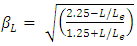
 ), MPa (psi)Gf = Interfacial fracture energy at the CFRP-concrete interface, N.mm/mm2 (lb.in/in2)L = bond length of CFRP strip, mm (in.)Le = effective bond length of CFRP strip, mm (in.)Pu = Ultimate load capacity of the bond between CFRP and concrete, KN (Kip)s = bond slip at the CFRP-concrete interface, mm (in.)so = bond slip at the mean bond strength (τmean), mm (in.)tf = CFRP strip, mm (in.)τ = Bond stress at the CFRP-concrete interface = P /(bf × L), MPa (psi)τmax = Maximum bond strength at the CFRP concrete interface = P /(bf × Le), MPa (psi)βw = CFRP to concrete width ratio factorβL = CFRP to concrete effective length to actual length ratio factor