-
Paper Information
- Paper Submission
-
Journal Information
- About This Journal
- Editorial Board
- Current Issue
- Archive
- Author Guidelines
- Contact Us
International Journal of Composite Materials
p-ISSN: 2166-479X e-ISSN: 2166-4919
2016; 6(5): 159-166
doi:10.5923/j.cmaterials.20160605.03

Wear Behaviour of Alumina Filled Al-Cu Metal-Matrix Composite Bushing with Rotating Steel Shaft
 Abstract
 Reference
 Full-Text PDF
 Full-text HTML
V. K. Srivastava
Department of Mechanical Engineering, Indian Institute of Technology (BHU), Varanasi, India
Correspondence to: V. K. Srivastava, Department of Mechanical Engineering, Indian Institute of Technology (BHU), Varanasi, India.
| Email: |  |
Copyright © 2016 Scientific & Academic Publishing. All Rights Reserved.
This work is licensed under the Creative Commons Attribution International License (CC BY).
http://creativecommons.org/licenses/by/4.0/

Wear test set-up is designed to measure the sliding temperature and wear loss of alumina filled Al-Cu metal matrix composite bushing in rotating steel shaft with the variation of weight percentage varying from 1%, 3%, 5%, 8% and 10% respectively. Powder metallurgy method is used to fabricate the bushing composite samples. Each sample is sintered at 450°C temperature for 90 min after that samples are quenched in water and oil. The results show that compressive strength, Vicker’s hardness decreases and wear loss increases with increases of weight percentage of alumina filler. The wear loss and sliding temperature also increases with increase of load and sliding time during sliding of composite bushing on the rotation of steel shaft. The scanning electron microscopy results show that the deformation and fragmentation of asperities occur in the wear surfaces. Also, fine layer is trnasformed on the composite surfaces in the form of fine debris.
Keywords: Alumina, Aluminium, Copper, Epoxy resin, Compressive strength, Vicker’s hardness, Wear Loss
Cite this paper: V. K. Srivastava, Wear Behaviour of Alumina Filled Al-Cu Metal-Matrix Composite Bushing with Rotating Steel Shaft, International Journal of Composite Materials, Vol. 6 No. 5, 2016, pp. 159-166. doi: 10.5923/j.cmaterials.20160605.03.
Article Outline
1. Introduction
- Bearing materials are expected to have good properties such as high load capacity, low friction coefficient, high corrosion resistance, high wear resistance and high heat conductivity. All of these properties significantly affect the fatigue and wear life. The journal bearing is mostly fixing with the rotating shafts to support the rotor, when mechanical systems operate at high speed for the use of turbine, centrifugal pumps etc [1]. Slide bearing wide spread in crank mechanisms carry the dynamical loads through the oil film layer as thin as 1 µm. This implies the need of mutual conformation of cooperating surfaces. The journal bearing material is generally white metals (tin-based or lead-based), aluminum and copper based alloys. Lead is widely used to prevent the inherent toxicity that causes acute and chronic effects. The environmental effects can be minimized with the use of lead [2]. The hard material is used as reinforcement for the improvement of mechanical properties such as hardness and compressive strength, which are desirable properties for bearing application. Tin-based material is used as matrix for the metal-matrix composite. This material is highly compatible to avoid seizure and reduces operating costs considerably [3, 4]. Metal-matrix composite (MMC) materials have high stiffness and wear resistance. This is suitable for heavier duty parts like leaf spring bushing, connecting rod and pistons, at high load and speed etc. Normal load and sliding velocity are the important parameters that affect the tribological performance of metals and alloys. Copper and copper based alloys are widely used in many applications because of high wear resistance and self-lubrication property. Copper based alloys are generally used as bearing materials to achieve a high wear resistance [5-7]. The wear resistance is generally affected by various factors, which is not possible to control during the operation. The particulate MMCs, which have isotropic and homogenous properties, are easily adaptable to the current engineering design practice [8-10]. In the high load regime, friction coefficient decreases with load for many metallic pairs. It is believed that due to a large amount of wear debris and increased surface roughening, friction force decreases. For different material combinations, friction may increase or decrease when sliding velocity increased. During friction process, because of increased adhesion of counterface pin material on disc, friction increases with the increase in sliding velocity [11].The aluminum matrix composites have low density, high stiffness, low cost, ease of processing, low melting point, high work ability, corrosion resistance, and availability of variety of alloy systems. Aluminum alloys are used as bearing materials where low friction is required. Due to these properties, the aluminum metal matrix composites are being widely used in the automobile, aerospace, and electrical packaging industries [12-19]. The overall wear rate of commercially available aluminium is more than aluminium matrix composites at applied loads. The wear rate increases with increase of load for commercially available aluminium and aluminium matrix composite [20]. The micro size of filler particles in aluminium matrix composites increases the wear rate in dry sliding condition. The reason for the effect of size is that the smaller particles easily plough and increases wear rate [21]. However, when particle size varies from micro to nano range, wear rate decreases due to accumulation of filler on the sliding surface. This leads to decrease wear rate and abrasion of counter-surface by nanocomposites, it is less as compared to microcomposites [22]. In the present paper, the main objective is to fabricate the Alumina filled Al-Cu metal-matrix composites by powder metallurgy method with the variation of weight percentage of alumina filler. The wear loss and sliding temperature were measured from the fabricated wear test rigs.
2. Experimentation
2.1. Materials and Specimen
- Aluminium (60 μm, 99.7% purity), copper (60 μm, 99.7% purity) and alumina (100 μm) particles were used for the fabrication of alumina filled Al-Cu metal matrix composite. Al and Cu powders were mixed in the ratio of 4:1 with the mechanical stirrer method. Powder was mixed with the help of stirrer (Heidolph RZR 2020) at the 160 rpm for 20 minute so that the particles get dispersed homogenously. The alumina filler was added in the mixture of Al-Cu particles. The alumina particle was added with the variation of weight percentage from 1%, 3%, 5%, 8% and 10% respectively to fabricate the alumina filled Al-Cu metal matrix composites. Circular bushing type specimens were fabricated by metallurgical compaction method. Special type of mold (punch and die, Fig. 1(a)) was prepared to obtain the bush type of sample. The mixed powder of specified composition was filled in the die and compressed by plunger at 8.0 kpsi pressure on compression moulding machine as shown in Fig. 1(b).
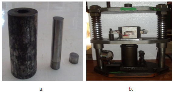 | Figure 1. Photograph of (a) Plunger and die and (b) compression moulding machine |
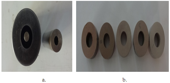 | Figure 2. (a) Complet set of die and punch for bush sample and (b) bush samples |
2.2. Compression and Hardness Tests
- Circular specimens were tested for compressive strength on universal testing machine (UTM). To carry out compression test BRAZALIAN disk type specimens were prepared. The cross head speed was fixed 2 mm/min. The fracture load was recorded to calculate the compressive strength.Hardness test was performed to obtain the Vicker’s hardness of the samples. The Vicker’s hardness testing was carried out on Vickers hardness testing machine (Mechatronic Control System, Model- 2012-13/673). All specimens were polished before hardness test. In order to eliminate the segregation effect, three hardness readings were measured at 5 Kg load for each specimen at different locations. The load was applied for 30 seconds. The indentation was noted from the microscope, which was attached with the machine and the readings were taken from the scale provided.
2.3. Wear Test
- The wear test rig set-up was designed and fabricated for the measurements of wear loss and sliding temperature of alumina filled Al-Cu composite bush specimens. Each part of the wear test set-up was designed as per ASTM standard to calculate the speed of stepped pulley, shaft forces in bush bearing specimen. Bearing was selected according to the acting forces on the bearing. The focres were calculated with the bush bearing position 1 and 2 along horizontal, vertical and radial direction. The design and fabrication details are reported in M. Tech. thesis, Department of Mechanical Engineering, Indian Institute of Technology, BHU [23]. The shaft was design to bear the horizontal, vertical and radial forces. Mild steel material was used for the housing of the bush bearing and cast iron was used for pully. The steel (EN9) shaft (10 mm diameter) was selected to fix the bush of alumina filled Al-Cu composite specimen. The schematic diagramme of bush bearing test rig is shown in Fig. 3.
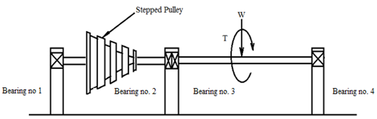 | Figure 3. Schematic diagram of wear test rig |
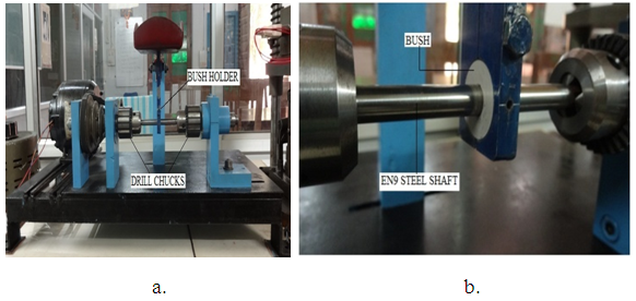 | Figure 4. Photograph of (a) wear test rig for bush bearing test and (b) bush bearing holder |
3. Results and Discussion
3.1. Variation of Compressive Strength and Hardness
- Figs. 5 and 6 indicate that the Vicker’s hardness and compressive strength influenced with the effect of weight percentage of alumina filler in Al-Cu composite specimens under the normalized, oil and water quenched environments. The oil quenched specimen shows markedly higher compressive strength than the water quenched and normalized specimen, whereas water quenched specimen show higher Vicker’s hardness than the other envoirnment. Compressive strength and hardness decreases with increase of alumina content irrespective of the quenching media. The hardness gradually decreases with increase of alumina filled Al-Cu composite under all the sintering enviornments, as shown in Fig. 5, which reflectes the agreement of general hardness theory [12]. Although the effect of sintering environment on hardness is only marginal, a significant effect is exerted on bulk behaviour of compressive strength as can be seen in Fig. 6. The lower values of compressive strength for the compacts sintered in water and air are likely to be result of poor bonding, possibly as a result of oxidation of alumina during sintering.
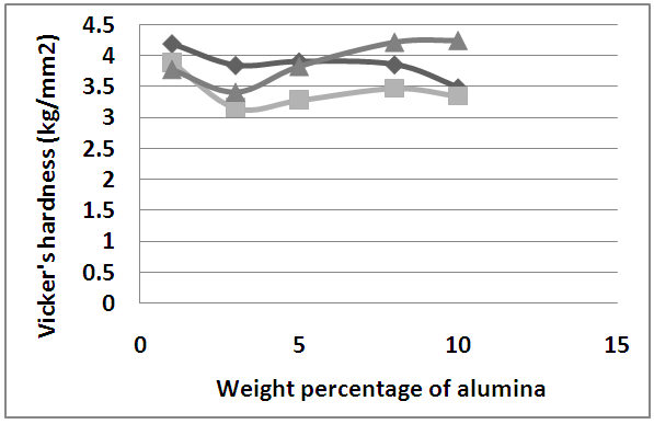 | Figure 5. Variation of Vicker’s hardness with weight percentage of alumina in different environment |
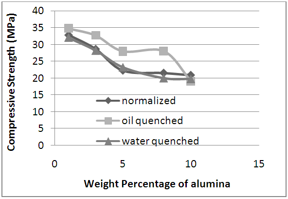 | Figure 6. Variation of compressive strength with weight percentage of alumina in different environment |
3.2. Variation of Wear Loss
- The effect of load, speed, sliding time and environment on wear loss of Al-Cu composite with the variation of weight percentage of alumina is presented in Figs. 7-15. The results show that the wear loss increases with sliding time of normalized Al-Cu composite as presented in Fig. 7. The wear loss is marginally affected with the variation of weight percentage of alumina filler at constant sliding speed of 700 rpm and load 200 grams.
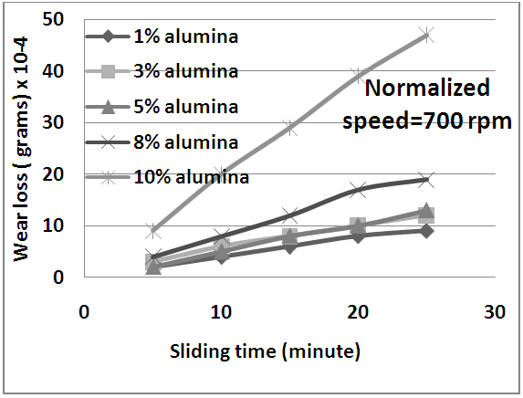 | Figure 7. Variation of wear loss with sliding time of normalized Al-Cu-alumina particulate composites |
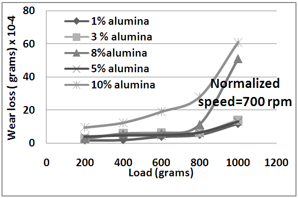 | Figure 8. Variation of wear loss with load of normalized Al-Cu-alumina particulate composites |
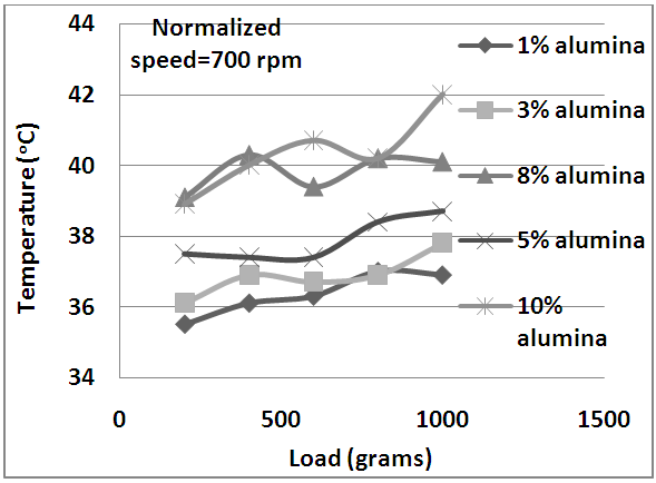 | Figure 9. Variation of sliding temperature with load of normalized Al-Cu-alumina particulate composites |
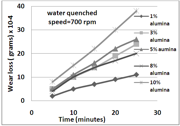 | Figure 10. Variation of wear with sliding time of water quenched Al-Cu-alumina particulate composites |
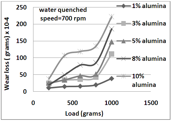 | Figure 11. Variation of wear with load of water quenched Al-Cu-alumina particulate composites |
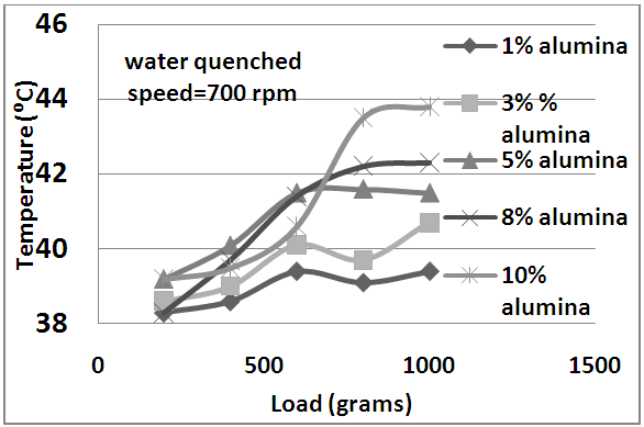 | Figure 12. Variation of sliding temperature with load of water quenched Al-Cu-alumina particulate composites |
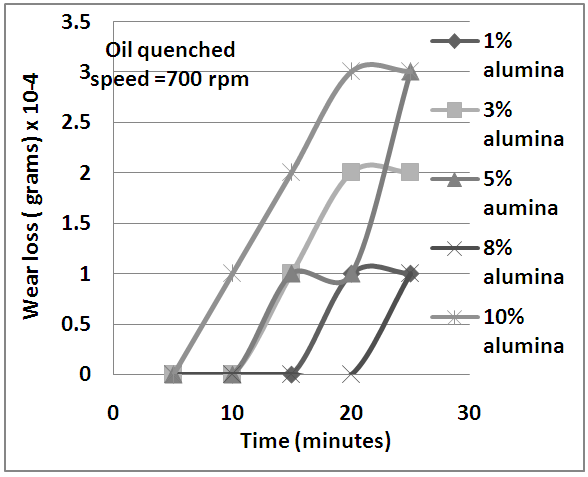 | Figure 13. Variation of wear with sliding time of oil quenched Al-Cu-alumina particulate composites |
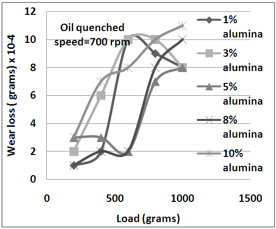 | Figure 14. Variation of wear with load of oil quenched Al-Cu-alumina particulate composites |
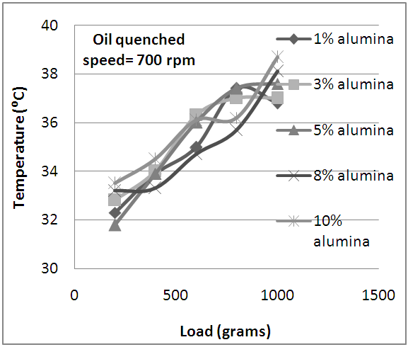 | Figure 15. Variation of sliding temperature with load of oil quenched Al-Cu-alumina particulate composites |
3.3. Morphological Behaviour
- It is evident from SEM micrograph Fig. 16 (a) that the copper particle is distributed uniformly in the aluminium particles. The fine crack propagated through the boundaries of the particle as shown in Fig. 16 (b). The crack is appeared in the intergranular not transgranular shape, which can be identify from Fig. (c & d), because in the case of transgranular failure there must be sharp edges at the fractured surface [19].
 | Figure 16. SEM images of alumina filled Al-Cu composite shows (a) distribution of Cu particle (b) fine cracks propogated (d) cracks appeared in transgranular shape under compressive load |
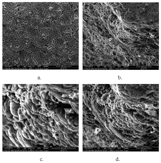
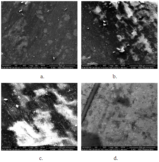 | Figure 17. SEM images of wear surfaces of (a) normalized, (b & c) water quenched and (d) oil quenched alumina loaded Al-Cu matrix |
3.4. Explanations
- Under applied load, the load is transferred from the weaker aluminium matrix, across the alumina-Al-Cu interface, to the typically higher stiffness reinforcement. In this manner, strengthening takes place by the reinforcement carrying much of the applied load, this is direct strengthening of particulate composite [14]. This results show that the compressive strength decreases with increase of weight percentage of alumina in Al-Cu composite, as it is evident from the SEM images showing the amount of porosity, and voids present in the specimen, which affect the transfer of load from matrix material to the reinforcement inefficiently. From the SEM images it can also be concluded that the interfacial strength between the reinforcement and the matrix particles is affected [15] and therefore weaken the interface bonding in between particles.The compressive strength is also increased in particulate composite due to perfect bonding and agglomeration of particles and strengthening effect [16]. Fig. 6 shows that oil quenched alumina filled Al-Cu composite have higher compressive strength upto 8% than the normalized and water quenched specimen due to indirect strengthening. It is also evident that there is no significant effect on increase in strength due to indirect strengthening of composite specimen. Vicker’s hardness of oil quenched was less than that of normalized and water quenched alumina loaded Al-Cu composite. It is fact that oil is filled the pores and voids within the specimen and then the interfacial strength is weaken, which allow to flow the particles from the pores much easier than the normalized and water quenched specimen. The vicker’s hardness reduces upto 3% alumina and icreases after 4% alumina filled Al-Cu composites. However, vicker’s hardness affected with increase of alumina filler, due to aggolomeration of alumina filler. After 10% alumina filler hardness decreased because of the weak interface bond strength in between alumina, Al and Cu particles [18].Wear loss increases with increase of alumina filled Al-Cu matrix normalized composites. 10% alumina filled Al-Cu composite showing higher wear loss and increases sharply as the load increases. For 5% alumina loaded specimen, wear loss increases rapidly after 800g applied load. It can also be noted that the wear loss in water quenched alumina filled Al-Cu composite is more than the normalized composite due to fragmentation of the particles in water quenched media. This led to the more wear in water quenched composite than the normalized specimen. The wear loss in oil quenched specimen is very less because oil entrapped in the pores and acted as lubricant. The sliding temperature rises due to increase of wear and it is greatly affected by the environment condition.
4. Conclusions
- Based on the experimental observation following conclusions can be drawn;i. Compressive strength of the alumina filled Al-Cu composite decreases with increase of weight percentage of alumina. Compressive strength of oil quenched alumina filled Al-Cu matrix composite is higher than the normalized and water quenched composite.ii. Vicker’s hardness of normalized alumina filled Al-Cu composite is nearly 3% higher than the oil and water quenched composite. Vicker’s hardness of alumina filled oil and water quenched composite gradually decreases upto 3% of alumina filled Al-Cu composite and then increases with increase of weight percentage of alumina filler.iii. The wear loss of water quenched 10% alumina filled Al-Cu composite is more than the normalized and oil quenched Al-Cu composite. The wear loss of alumina filled oil quenched composite is lowest among the normalized and water quenched composite.iv. The sliding temperature increases with increase of load in all environments, but it is stabilized after load 0.80g due to formation of thick film on the counter surface.
ACKNOWLEDGEMENTS
- The author would like to thank Mr. A.S. Pareta, M. Tech. Student and Department of Mechanical Engineering, Indian Institute of Technology (BHU), Varanasi-221005, India for their supports.