-
Paper Information
- Paper Submission
-
Journal Information
- About This Journal
- Editorial Board
- Current Issue
- Archive
- Author Guidelines
- Contact Us
International Journal of Composite Materials
p-ISSN: 2166-479X e-ISSN: 2166-4919
2016; 6(4): 140-143
doi:10.5923/j.cmaterials.20160604.07

Calculation of Acoustic Transmission Intensity of 1-D Composite Models for Sound Absorber Wall Application: Case Study on Wood – Epoxy Composite
 Abstract
 Reference
 Full-Text PDF
 Full-text HTML
Widayani1, Sparisoma Viridi1, Siti Nurul Khotimah1, Damar R. Adhika2
1Nuclear Physics and Biophysics Research Group, Faculty of Mathematics and Natural Sciences, Institut Teknologi Bandung, Bandung, Indonesia
2Engineering Physics Research Group, Faculty of Industrial Engineering, Institut Teknologi Bandung, Bandung, Indonesia
Correspondence to: Widayani, Nuclear Physics and Biophysics Research Group, Faculty of Mathematics and Natural Sciences, Institut Teknologi Bandung, Bandung, Indonesia.
| Email: |  |
Copyright © 2016 Scientific & Academic Publishing. All Rights Reserved.
This work is licensed under the Creative Commons Attribution International License (CC BY).
http://creativecommons.org/licenses/by/4.0/

One application of composite materials is for use as building walls. One characteristic of building walls is they can absorb acoustic waves. Buildings near crowded streets perhaps need the walls which absorb sound better than other areas. This paper presents the calculation of acoustic transmission of 1-D composite model containing two component materials. In general, the wave intensity decreases when it comes to boundary surface of different media, and attenuated during propagation in a medium. The acoustic impedance and attenuation coefficient data used are referred to wood and epoxy. To study the influence of physical properties on the acoustic transmission of the 1-D composites, the output acoustic intensities are calculated for several conditions: different total thicknesses for a pair of wood – epoxy, different fractions of wood (17-58)% for a pair of wood - epoxy, and two different thicknesses: 0.8 cm and 0.4 cm of components for the arrangement of one pair and two pairs of wood – epoxy (50:50), respectively, for the same total thickness. The acoustic transmissions are calculated for incident acoustic intensity of heavy traffic, i.e. 80 dB (10-4 watt/m2). The results show that the output acoustic intensity of the composite model is lower than that of wood and epoxy. The output acoustic intensity decreases as wood fraction increases. It is also noted that the size of component affected the output acoustic intensity, where the smaller the size, the lower the intensity.
Keywords: 1-D composite model, Acoustic, Impedance, Attenuation, Intensity
Cite this paper: Widayani, Sparisoma Viridi, Siti Nurul Khotimah, Damar R. Adhika, Calculation of Acoustic Transmission Intensity of 1-D Composite Models for Sound Absorber Wall Application: Case Study on Wood – Epoxy Composite, International Journal of Composite Materials, Vol. 6 No. 4, 2016, pp. 140-143. doi: 10.5923/j.cmaterials.20160604.07.
Article Outline
1. Introduction
- Composite materials show specific properties which are formed as a combination of its component properties. Many studies focus on mechanical properties of composites. But beside mechanical property, there are some other properties that are also interesting to study, such as absorption / transmission of acoustic wave through composites [1-5]. The composite which transmits very low acoustic intensity is potentially used for a sound-absorption wall. Many new composite materials have been produced and utilized in our daily life. One of important application of composite materials is as building materials, such as materials for use as roof and wall [5-7]. In busy cities, people facing acoustic problems, especially for people who live near crowded streets. Therefore, it may need walls which can absorb acoustic waves (noise). Studies on composites have been attracted many researcher. The studies cover experimental, numerical and theoretical aspects [8-10]. All of these aspects are important in composite study. This paper reports the study of acoustic transmission intensity of 1-D composite models. In this study, the acoustic transmission intensity through the 1-D composite models are calculated, relative to the incident acoustic intensity.Simple composites contain only two components. The components normally referred as matrix and filler. Even only two components, there are some different ways to form a composite. For example, variation in the component fraction, sizes and the arrangement may result in composites with different properties. This paper presents the calculation on output acoustic intensity after sound at heavy traffic (80 dB) propagates through 1-D of two components composite model.
2. Theory
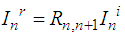
- The incident acoustic waves from air go through composite that consists of two components. The acoustic intensity decreases when it goes through boundary surface to the next media, i.e. from air to the first component. This decreasing intensity happens for each boundary surface. Next, in each component, the acoustic intensity also decreases as it propagates in the component. Thus, in total, the intensity of transmitted acoustic waves will lower than the initial intensity.Theoretically, when waves come from medium 1 to medium 2, it will face a boundary surface, and a part of the waves will be reflected and the rest will be transmitted. The intensity of reflection and transmission waves depends on reflection and transmission energy coefficient which are depend on acoustic impedances of the two media, according to the following formulations [11].
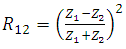 | (1) |
 | (2) |
 | (3) |
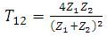
 | Figure 1. Schematic picture of waves that is going through a medium: it is facing two interfaces. I’ and I is wave intensity after and before it propagate in a distance L in the medium. The input wave intensity (Ii) is higher than output intensity (Io) due to interfaces and attenuation in the medium |
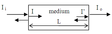
 | Figure 2. Wave intensities for three different medium with mechanical impedances Zn, Zn+1, and Zn+2 |
 | (4a) |
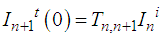 | (4b) |
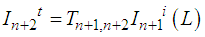 | (4c) |
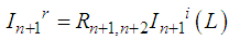 | (4d) |
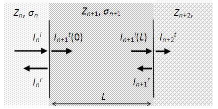
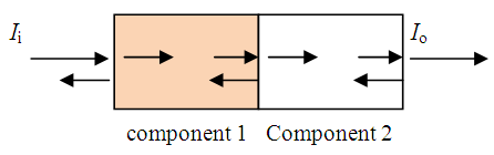 | Figure 3. Schematic picture of waves that is going through a composite consists of a pair of two components: it is facing three interfaces. The wave attenuates when propagating in each component |
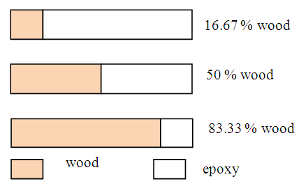 | Figure 4. Illustration of variation of wood fraction for the same total width of composite that is containing only one pair of two components |
3. Method
- Most of the data used in this study are referred to wood-epoxy composite [13-15], i.e. mechanical impedance (Z) of air, epoxy and wood is 413 Rayl , 314 MRayl and 1.57 MRayl, respectively. Attenuation coefficient (σ) of epoxy and wood is 8 dB/cm (2 MHz) [14] and 22 dB/cm [15], respectively. Attenuation coefficient depends on frequency, but as an approach, the attenuation coefficient of epoxy and wood used in this work is 8 dB/cm and 11 dB/cm, respectively. All the calculations are conducted using common spreadsheet program.In this study, the 1-D composite models containing two rectangular components. The important factor in this model is the width of the components, where the width of each component represents its volume fraction. Thus variation of component fraction is studied via variation of component width. In the calculation, for the total width of 1.2 cm, the fraction of wood is varied between 17 to 58%.On the other hand, a specific composition can be built using many different number of component pair. In this study, we investigate the influence of number of pair for the component composition of 50:50. In this scheme, the more number of pair represents smaller size of component.
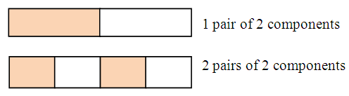 | Figure 5. Illustration of 2 component composite (50:50) with two different number of pairs |
4. Results and Analysis
- For all of the calculations, the initial wave intensity before entering composites is defined as 80dB (intensity of heavy traffic) [16]. The output intensity, i.e. after leaving composites, is also calculated in dB unit.
4.1. Acoustic Attenuation of Composite Compared to Its Components
- The output intensity of 1-D composite model is shown in Figure 6, together with output intensity of epoxy only and wood only. The composite model used is containing epoxy and wood with the same fraction (50% each). The total width is varied from 1.2 to 2.2 cm.
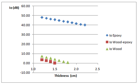 | Figure 6. Transmission wave intensity plot shows that intensity of transmission wave after goes through composite is in between of their components, i.e. higher than that of epoxy but lower than wood |
4.2. The Influence of Component Fraction
- To study the influence of component fraction on the intensity of transmission wave after goes through composite, the component fraction is varied from 17 to 58 % for the total composite model width is 1.2 cm. Figure 7 shows the plot of Io versus wood fraction. Io decreases linearly as wood fraction increases. This also means that Io increases linearly as epoxy fraction increases. This condition occurs because of attenuation coefficient of wood is higher than that of epoxy, and higher wood fraction means longer path in wood, thus the wave attenuated more.
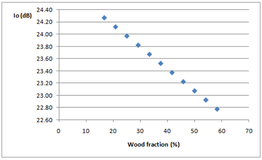 | Figure 7. The influence of wood fraction on the intensity of transmission wave after goes through composite |
4.3. The Influence of Component Size
- Two components 1-D composite model of a certain fraction and same total thickness can be constructed in different component sizes. To study the influence of component size on the intensity of transmission wave after goes through composite, we use two different thickness of each component (epoxy and wood): 0.8 cm and 0.4 cm for the same total thickness: 1.6 cm. We use two compositions for 1-D composite models: (1) wood (0.8 cm) and epoxy (8 cm); (2) wood (4 cm), epoxy (4 cm), wood (8 cm) and epoxy (4 cm). Thus the fraction of wood is always 50%. The calculated output intensity for model (1) and model (2) is 19.27 dB and 18.25 dB, respectively. Smaller component size gives more interface facing by the wave during the propagation. This results in lower intensity of transmission wave.
5. Conclusions
- Acoustic absorption study of 1-D Composite Models has been carried out using data referred to wood-epoxy composite through the calculation of output intensity, Io. As expected, this study shows that Io of composite is in between of their components, i.e. higher than that wood of but lower than epoxy. The Io of composite depends on the fraction of the composite and the size of component. More portion on component with higher attenuation coefficient, results in lower output wave intensity. Smaller component size gives lower transmission wave intensity. Using smaller component size, it can be expected to have composite with better acoustic absorption.
ACKNOWLEDGEMENTS
- The authors express gratitude to Institut Teknologi Bandung, and Ministry of Higher Education and Research, Indonesia for supporting facility during this work through “Penelitian Unggulan Perguruan Tinggi – Riset Desentralisasi Dikti” with contract number 585f/I1.C01/PL/2016.