N. Jeevan Kumar1, P. Ramesh Babu2
1Department of Mechanical Engineering, CMR Engineering College, Research Scholar, Osmania University, Hyderabad, Telangana, India
2Associate Professor in Mechanical Engineering, Osmania University, Hyderabad, Telangana, India
Correspondence to: N. Jeevan Kumar, Department of Mechanical Engineering, CMR Engineering College, Research Scholar, Osmania University, Hyderabad, Telangana, India.
| Email: |  |
Copyright © 2016 Scientific & Academic Publishing. All Rights Reserved.
This work is licensed under the Creative Commons Attribution International License (CC BY).
http://creativecommons.org/licenses/by/4.0/

Abstract
In recent years carbon fibre-reinforced polymers (CFRP) emerged its increasing demand in aerospace engineering. Due to their high specific strength to weight ratio, these composites offer more characteristics and considerable advantages compared to metals. Metals, unlike composites, offer plasticity effects to evade high stress concentrations during postbuckling. Under compressive load, composite structures show a wide range of damage mechanisms where a set of damage modes combined together might lead to the eventual structural collapse. A Pre-damaged configuration is loaded to study the delamination location and mode for delamination initiation and propagation. A parametric study is conducted to investigate the effect of the location of the delamination propagation when delamination is embedded i) in between plies of the skin ii) in between plies of the stiffener hat iii) in between skin-stiffener interface of the hybrid laminated curved composite stiffened panel. The influence of location of delamination on crack growth and collapse behavior is analyzed using analysis tool. An analysis tool is applied that includes an approach for predicting interlaminar damage initiation and interlaminar damage growth as well as in-plane damage mechanisms to predict the design of defect free panel.
Keywords:
Hybrid composites, Curved stiffened panel, Delamination, VCCT, SERR
Cite this paper: N. Jeevan Kumar, P. Ramesh Babu, Analysis of Embedded Delamination Growth in Hybrid Laminated Curved Composite Stiffened Panels, International Journal of Composite Materials, Vol. 6 No. 4, 2016, pp. 100-120. doi: 10.5923/j.cmaterials.20160604.03.
1. Introduction
Fiber-reinforced plastics (FRPs) are often used for high performance structures since this material combines high stiffness, high strength and low weight. The application area ranges from sports utilities to airframe structures such as tennis rackets, bicycles, wings or airfoil parts and rotor blades. First attempts have also been made to use FRPs for aircraft fuselage structures. Composite laminates are highly customizable because fiber orientations can be adapted to any particular stress state. For optimal exploitation of material reserves, several fracture scenarios should be taken into consideration during the design phase. Failure in laminated composites can be caused by intralaminar fracture (e.g. fiber fracture, transverse matrix cracking, fiber–matrix debonding and fiber buckling) or interlaminar fracture, namely delamination. Delamination is one of the most frequent failure modes in FRPs due to their lack of reinforcement in thickness direction. On the other hand, interlaminar failure is especially dangerous because it can lead to a significant reduction of the load carrying capacity in absence of any visible damage. Hence, delaminations should be accounted for in the design phase which requires reliable and robust simulation tools. There are two main targets in the numerical treatment of delamination: Simulation of (i) delamination initiation and (ii) delamination propagation. Delamination onset is usually predicted using stress-strength based criteria [1]. Since geometrical discontinuities often lead to highly over-estimated stresses, predictions incorporating solely such criteria are not reliable. Thus, fracture mechanics approaches are often employed. The most prominent fracture mechanics approach is the virtual crack closure technique (VCCT) which has been proposed by Rybicki and Kanninen [2]. Jeff. W.H. et al. [3] developed buckling behavior of panels and coupled with a linear elastic fracture mechanics approach to determine damage critically based on the “no-growth” principle. The structural behavior in the post-buckling range and its interaction with the damage parameters were analyzed. Nathan D. Flesher et al. [4] incorporated the mesoscale composite damage model (MCDM) and a new component damage indicator into a finite element code to predict the initiation and evaluation of damage and then final failure of fibrous composites structure subjected to various combinations of tension ,compression, shear and pressure loading. They modeled the stiffened panel as a structure consisting of web, flange, skin and interface between the flange and the skin. The effect of nonlinear contact upon natural frequency of the stiffened composite plate with Pre-damages such as delamination of skin panel and/or debonding interfaces between skin panel and stiffeners was studied by the finite element method based on hump resonance principle by Haoran Chen et al. [5].Zoltan Mikulik et al. [6] evaluated an analytical crack tip element (CTE) methodology and applied to predict skin-to-stiffener separation, which is a typical failure mode in aerospace by the CTE and the predicted load for initiation agreed with the average of a set of experimental data. Delamination and skin-stringer separation are examined in the frame work of finite element method by W. Waagner et al. [7].A cohesive interface element is used which is written in stress-strain relationship. They concluded that only tensile normal or tensile shear stresses provoke damage. They added a penalty term to avoid the interpenetration of the crack faces. Adrian C. Orifice et al. [8] were conducted experimental and numerical investigations into the damage growth and collapse behavior of composite blade-stiffened structures. They tested four panel types consisting of two secondary bonded skin-stiffener designs in both undamaged and pre-damaged configurations.Ronald Krueger et al. [9] analyzed a shear loaded stringer reinforced composite panel to evaluate the fidelity of computational fracture mechanics analyses of complex structures. They calculated a failure index by correlating the results with mixed-mode failure criterion of graphite/epoxy materials.S. Lauterbach et al. [10] conducted a parametric study to investigate the effect of the skin-stiffener debond parameters such as length, width and location on crack growth and collapse behavior of the panel. It is found that the sensitivity of the panel design to the damage parameters is highly dependent on the post buckling mode shape or displacement pattern and particularly the extent to which this influences the conditions at the crack front. A. Faggiani et al [11] is presented an interlaminar damage model, based on a continuum damage mechanics approach, to model the damage mechanism occurring in carbon fibre composite structures incorporating fibre tensile and compressive breakage, matrix tensile and compressive fracture and shear failure. The damage model, together with interface elements for capturing interlaminar failure, is implemented in a finite element package and used in a detailed finite element model to simulate the response of a stiffened composite panel to low velocity impact.Elisa Pietropaoli et al. [12] combined use of the virtual crack closure Technique and of a fail release approach for the analysis of delamination growth phenomena in composite structures has been enhanced with a front-tracing algorithm and suitable expressions for the evaluation of the Strain Energy Release Rate when dealing with non-smoothed delamination fronts.T.M. Koh et al. [13] presented an experimental study into the improvement to the damage tolerance of T-shaped stiffened carbon fiber/epoxy panels when reinforced with thin Z-pins .They concluded with experimental analysis that Z-pins were highly effective at improving the damage tolerance of T-stiffened panels that contained a single bond-line delamination crack or multiple cracks along and near the bond-line caused by impact loading. A.P. Herman et al. [14] presented a material and experimental investigation into the detection of defects in composite T-stiffened panels using vibration analysis. The analysis was performed on carbon fibre /epoxy laminate panels containing a delamination crack or porosity. From the literature it is evident that most of the studies are based on numerical approach and most of the studies were focused on both skin and stiffeners were made of same fibres.N. Jeevan Kumar et al. [15] investigated that the panel with I- stiffeners having the more load baring capacity than the panel with straight stiffeners or with T- stiffeners. They also investigated that when the skin and stiffener of the panel made of different materials, skin with E-glass epoxy and stiffener with Carbon epoxy having the maximum load carrying capacity compared to other material combination.From the literature it is evident that most of the studies are based on numerical approach and most of the studies were focused on both skin and stiffeners were made of same fibres. The focus of this work is to analyze delamination damage mechanisms of hybrid laminated curved composite stiffened panel made of skin with E-Glass epoxy, I-stiffeners with carbon epoxy. The delamination inbetween plies of skin, inbetween plies of the stiffener hat and delamination between skin - stiffener interface are studied to predict the design of defect free panel. The main objective of this paper is to find out the strain energy release rate values which will be helpful to check the crack initiation points for the particular load at different locations to predict the delamination initiation and propagation in a skin stiffener joint which is used extensively in aerospace applications and further to assess the load reduction capacity of the hybrid laminated curved composite stiffened panel.
2. Design of Hybrid Laminated Curved Composite Stiffened Panel
A 3D deformable planar shell to represent as skin and I-stiffener, skin is made of E-glass Epoxy with ply sequence (90/0/90/0)s and stiffener is made of Carbon Epoxy with ply sequence (90/0/90/0)s with specified scaled configurations was modeled and assembled to represent as a hybrid laminated curved Composite Stiffened Panel using Abaqus/CAE&Abaqus/Explicit. Three different types of Pre-damaged models are established to study the delamination damage propagation effects.For case-1, a Pre-damaged panel is modeled and the delamination is embedded in between 4th and 5th plies of the skin. The delamination located 40mm away from the front and the size of the delamination is 33mm*40mm. In the second model (case-2) delamination is embedded 40mm away from the front and in between 8th and 9th plies of the stiffener hat. The size of the delamination is 33mm*33mm. In the third model (case-3) delamination region is embedded in the skin-stiffener interface and 40mm away from the front and the size of the delamination is 33mm*33mm. The three models are shown in Fig.1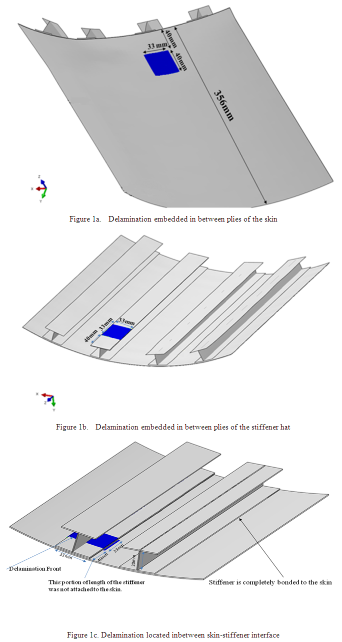 | Figure 1. Locations of the embedded delamination in stiffened panel for different cases |
2.1. Design Configuration & Constrains
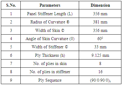
3D deformable planar shell to represent as skin and I-stiffener, skin is made of E-glass Epoxy and stiffener is made of Carbon Epoxy with below specified scaled configurations was modeled and assembled to represent as a hybrid Laminated curved composite Stiffened Panel using Abaqus/CAE&Abaqus/Explicit. Debond is embedded in different locations to study the effect of delamination (Fig. 1a Fig.1b, Fig1c). The resultant parameters of composite material are mentioned in Table 1.Table 1. Parameters in Composite Material
 |
| |
|
2.2. Loads and Boundary Conditions
The analysis is carried out by fixing one end of the composite plate as a cantilever and applying dynamic displacement boundary condition the other end. The loaded model is shown in below Fig.2a .The load input curve shown in Fig.2b.Ÿ One side fixed (fixed)Ÿ Symmetric on both sidesŸ Displacement Boundary condition, 40mm along Z-direction (one side)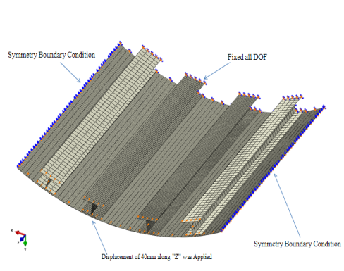 | Figure 2a. Hybrid Stiffened panel with boundary conditions |
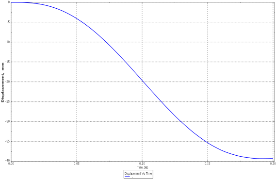 | Figure 2b. Displacement Vs Time (Load Input curve) |
3. FE Modeling and Analysis of Hybrid Laminated Curved Composite Stiffened Panel
In the first step, we defined the model of the physical problem in the form of geometry, material properties, generating a mesh and build the FE-model in the Abaqus software. This is known as Pre-processing. In the second step, we gave loading and boundary conditions and the model is developed by meshing. The model is selected as S4R element type from Abaqus/CAE software. The Figs.3a, 3b and 3c are shown Ply sequence for laminate skin (90/0/90/0)s, the Ply sequence for laminate stiffener (90/0/90/0)s and material orientation respectively are created a ply stack plot from a selected region to view the plies defined in the composite layup for analysis .The total number of elements are 46156 and the total number of nodes are 47251. The order of the element is assumed to be linear. The average aspect ratio is 1.14(96%), the worst aspect ratio 1.2(4%) and jacobian is 0.7 is taken as element quality. The analysis is carried out by fixing one end of the composite plate as a cantilever and applying displacement load at other end. A wide range of boundary conditions can be accommodated but only three kinds of boundary conditions are: one side fixed (fixed), on front side push and Symmetric on both sides. Later the model was simulated and the outputs are stored in binary files ready for post-processing. We can evaluate the results once the simulation has been completed. Strain Energy Release Rates GI, GII, GIII are calculated for opening, shearing and tearing modes interactively using the Visualization module of Abaqus/CAE or another postprocessor. Other fundamental variables have been calculated. The Visualization module, which reads the neutral binary output database file, has a variety of options for displaying the results, including colour contour plots, animations, deformed shapes and X–Y plots.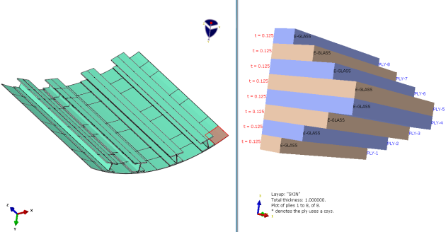 | Figure 3a. Ply sequence of laminate skin (90/0/90/0) |
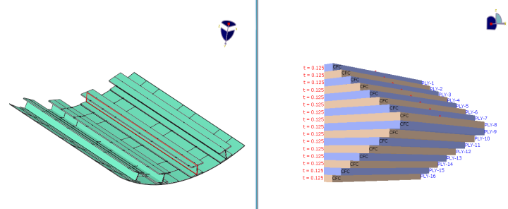 | Figure 3b. Ply sequence of laminate stiffener (90/0/90/0)s |
 | Figure 3c. Material orientation |
4. Analysis Approach
An FE tool is applied to predict the collapse of stiffened composite structures in compression by capturing the effects of the critical damage mechanisms. The approach for predicting the initiation of interlaminar damage inbetween plies of skin, inbetween plies of the stiffener hat and skin-stiffener interface is based on virtual crack closure technique (VCCT). The Virtual Crack Closure Technique (VCCT) uses the principles of linear elastic fracture mechanics (LEFM) and therefore, is appropriate for problems in which brittle crack propagation occurs along predefined surfaces. VCCT is based on the assumption that the strain energy released when a crack is extended by a certain amount is the same as the energy required to close the crack by the same amount. Fig.4a illustrates the similarity between crack extension from i to j and crack closure at j.In Fig. 4b nodes 2 and 5 will start to release when  Where GI is the Mode I energy release rate, GIC is the critical Mode I energy release rate, b is the width, d is the length of the elements at the crack front, FV,2,5 is the vertical force between nodes 2 and 5, and v1,6 is the vertical displacement between nodes 1 and 6. Assuming that the crack closure is governed by linear elastic behaviour, the energy to close the crack (and, thus, the energy to open the crack) is calculated from the previous equation. Similar arguments and equations can be written in two dimensions for Mode II and for three-dimensional crack surfaces including Mode III. In the general case involving Mode I, II, and III the fracture criterion is defined as
  Where G equiv the equivalent strain energy release rate is calculated at a node and G equiv C is the critical equivalent strain energy release rate calculated based on the user-specified mode-mix criterion and the bond strength of the interface. The crack-tip node will de-bond when the fracture criterion reaches the value of 1.0. The BK law model is described in Benzeggagh (1996) by the following formula:
  To define this model, you must provide GIC, GIIC and η. This model provides a power law relationship combining energy release rates in Mode I, Mode II, and Mode III into a single scalar fracture criterion. The elastic properties of the epoxy based cohesive layer material are specified in terms of the traction-separation response with stiffness values, E=850MPa, G1 =850MPa, GII =850MPa. For the VCCT debond approach, the B-K mixed-mode failure law is used with the below mentioned critical energy release rates. The elastic properties of the epoxy based cohesive layer materials are specified in terms of the traction-separation response with stiffness values [16] & [17].GIC=0.33KJ/m2, GIIC=0.8KJ/m2, GIIIC=0.8KJ/m2. The exponent B-K law is specied as
  .
.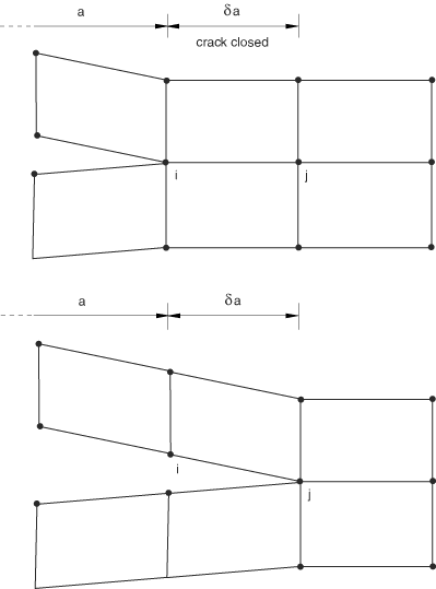 | Figure 4a. Mode I: The energy released when a crack is extended by a certain amount is the same as the energy required to close the crack |
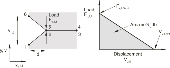 | Figure 4b. Critical Mode I energy release rate between two nodes (GIC) |
5. Results and Discussions
Before starting the simulation using Abaqus/CAE, the FE model is validated with the experimental results of stiffened panels with four straight stiffeners and is made of carbon epoxy composite with the ply sequence (90/0/90/0)s [15].
5.1. Case-1: Computations of SERRs for Hybrid Laminated Curved Composite Stiffened Panel when the Delamination is Embedded in between Plies of Skin
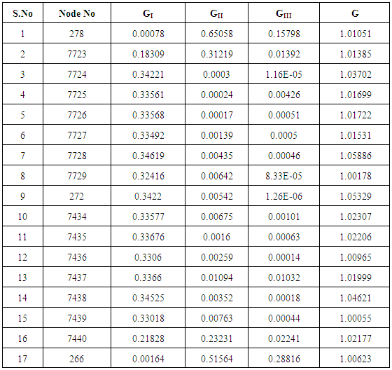
Delamination effects have been studied for the delamination embedded inbetween 4th and 5th plies of the skin based on VCCT criteria. Strain energy release rates are computed for the modes GI, GII, GIII & G which are mentioned in Table 2. The respective contour plots are shown in Fig.5. For mode GI at particular point the highest energy release rate 0.336762KJ/m2 is evaluated. Delamination initiation starts from this point and curve indicates the opening mode in which the crack initiation starts shown in Fig 6a. For mode GII at particular point highest energy release rate 0.650584KJ/m2 is evaluated and the curve indicates the In-Plane shearing mode in which the crack initiation starts shown in Fig 6b. For mode GIII highest energy release rate 0.288162 KJ/m2 is computed at particular point and the curve indicates out-of-Plane shearing or tearing mode in which the crack initiation starts shown in Fig 6c. Among the three modes of damages, In-Plane shear mode, GII is dominant when the delamination is embedded inbetween plies of the skin shown in Fig 6d. Damage propagation initiates at the location of maximum value of G. The damage propagation is not uniform along the delamination front length. Total energy release rate G, distribution along the delamination front length is shown in Fig 6e. It indicates the crack propagation behavior along delamination front length. It is observed that the total strain energy released is not constant along the delamination front length and SERRs are minimum at the ends of the delamination front.Table 2. Strain energy release rates (GI, GII, GIII & G) for delamination embedded in between plies of the skin
 |
| |
|
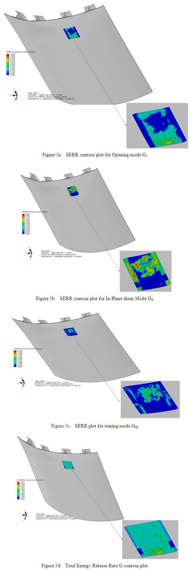 | Figure 5. Strain Energy Release Rate contour plots GI , GII, GIII & G for different modes when the delamination is embedded in between plies of the skin |
 | Figure 6. Distribution of Strain Energy Release Rates for different modes along the delamination front length when the delamination is embedded inbetween plies of the skin |
5.2. Case-2: Computations of SERRs for Hybrid Laminated Curved Composite Stiffened Panel when the Delamination is Embedded in between Plies of the Stiffener Hat
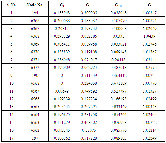
Delamination effects have been studied for the delamination embedded inbetween 8th and 9th Plies of stiffener hat based on VCCT criteria. Strain energy release rates are evaluated for the modes GI, GII, GIII & G which are mentioned in Table 3. The respective contour plots are shown in Fig. 7. Damage propagation initiates at the location of maximum value of G. The crack propagation for the modes are shown in Fig. 8. Among the three modes of delamination damages, In-Plane shearing mode, GII is dominant when the delamination is embedded inbetween plies of the stiffener hat shown in Fig 8d.The delamination damage propagates mainly towards In- plane shearing mode as compared to opening or tearing modes. As the delamination damage propagates, its tendency towards the tearing mode of failure is reduced where as it is more prone to delaminate in the In Plane shear mode. Total energy release rate G, distribution along the delamination front length is shown in Fig 8e. It indicates the crack propagation behavior along delamination front length and it is observed that the total strain energy released is not constant along the delamination front length and SERRs are varying at one end to the other end of delamination front. Table 3. Strain energy release rates (GI, GII, GIII & G) for delamination embedded in between stiffener hat
 |
| |
|
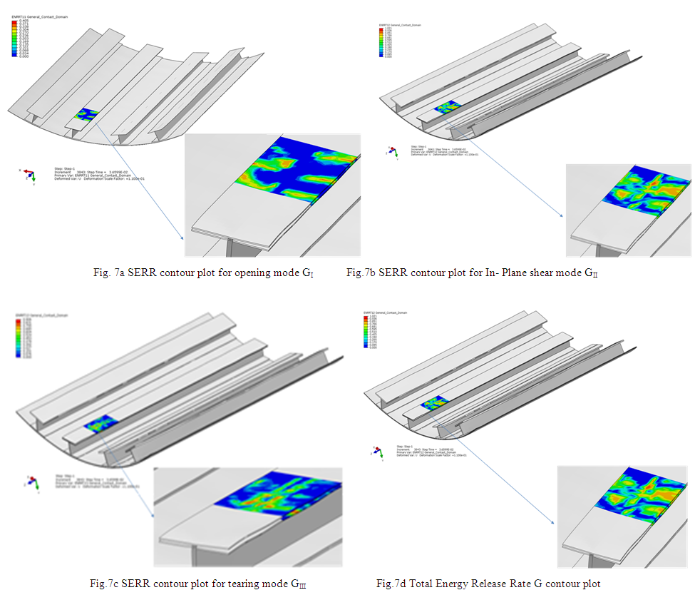 | Figure 7. Strain Energy Release Rate contour plots GI , GII, GIII & G for different modes when the delamination is embedded in between plies of the stiffener hat |
 | Figure 8. Distribution of Strain Energy Release Rates for different modes along the delamination front length when the delamination is embedded inbetween plies of the stiffener hat |
5.3. Case-3: Computations of SERRs for Hybrid Laminated Curved Composite Stiffened panel when Delamination is Embedded inbetween Skin and Stiffener Interface
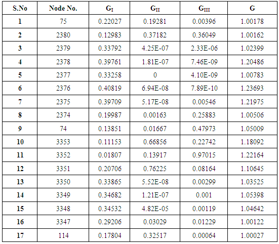
Delamination effects have been studied for the delamination embedded in between skin and stiffener interface based on VCCT criteria. Strain energy release rates are evaluated for the modes GI, GII, GIII & G which are mentioned in Table 4. The respective contour plots are shown in Fig. 9. Damage propagation initiates at the location of maximum value of G. The crack propagation for the modes GI, GII & GIII are shown in Fig. 10. Among the three modes of failures, Out-of-plane shearing mode or tearing mode, GIII is dominant when the delamination is embedded inbetween plies of the skin-stiffener interface shown in Fig 10d. The delamination damage propagates mainly in tearing mode as compared to opening or In Plane shear mode. As the delamination damage propagates, its tendency towards the inplane shearing mode of failure is reduced where as it is more prone to delaminate in the tearing mode. Total energy release rate G, distribution along the delamination front length is shown in Fig 10e. It indicates the crack propagation behavior along delamination front length. It is observed that the SERRs are not constant along the delamination front and SERRs are minimum at one end and maximum to the other end of delamination front length.Table 4. Strain energy release rates (GI, GII, GIII & G) for delamination embedded in between skin-stiffener interface
 |
| |
|
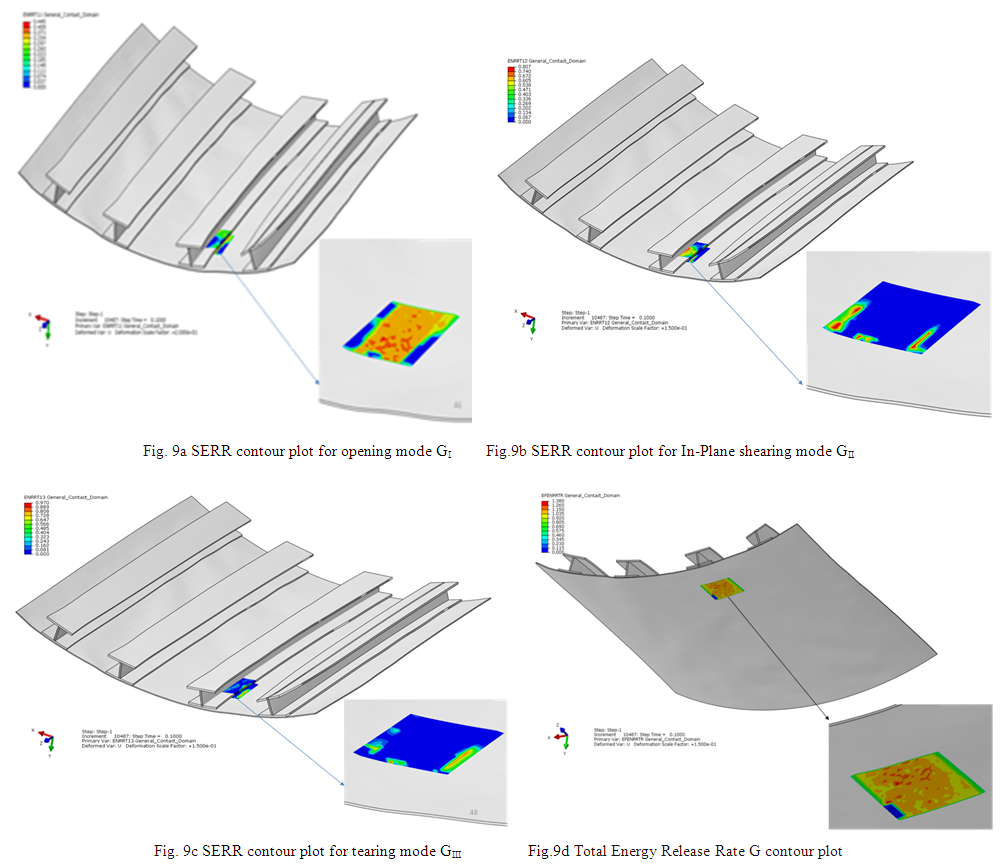 | Figure 9. Strain Energy Release Rate contour plots GI , GII, GIII & G for different modes when the delamination is embedded inbetween skin-stiffener interface |
 | Figure 10. Distribution of Strain Energy Release Rates for different modes along the delamination front length when the delamination is embedded inbetween skin- stiffener interface |
5.4. Case-4 Variations of Strengths in Stiffened Panel due to Delamination in between Plies of Skin, inbetween Plies of Stiffener Hat and inbetween Skin–Stiffener Interface
5.4.1. The Loss of Strength when the Delamination is Embedded inbetween plies of the Skin
The section force calculated for the defect free model with the 40mm displacement boundary condition is 149541N shown in Fig .11a. The section force calculated for the model when the delamination is embedded in between plies of the skin is 146240N shown in Fig .11b. The loss of strength due to delamination inbetween plies of skin with respect to defect free model is 2.20%.
5.4.2. The Loss of Strength when the Delamination is Embedded Plies of the Stiffener Hat
The section force calculated for the defect free model with the 40mm displacement boundary condition is 149541N shown in Fig.11c. The section force calculated for the model when the delamination is embedded inbetween plies of stiffener hat is 147345N shown in Fig.11d. The loss of strength due to delamination inbetween plies of stiffener hat with respect to defect free model is 1.46%.
5.4.3. The Loss of Strength when the Delamination is Embedded in between Skin-Stiffener Interface
The section force calculated for the defect free model with the 40mm displacement boundary condition is 149541N shown in Fig. 11e. The section force calculated for the model when the delamination is embedded inbetween skin-stiffener interface is 140153N shown in Fig.11f. The loss of strength due to delamination inbetween skin-stiffener interface with respect to defect free model is 6.27%.From the analysis of above four cases, it is evident that In-Plane shear mode GII is dominant in both the cases of delamination inbetween plies of the skin and the delamination inbetween plies of the stiffener hat. Tearing mode GIII is dominant when the delamination is embedded inbetween plies of the skin-stiffener interface. The influence on load carrying capacity is minimum when the delamination is embedded inbetween plies of the stiffener hat and reduces minimum load carrying capacity of the stiffed panel compared to other two cases. The influence on load carrying capacity is more when the delamination is embedded inbetween plies of the skin and it reduces more than double load compared to the delamination inbetween plies of the stiffener hat. The influence on load carrying capacity when the delamination is embedded inbetween plies of the skin-stiffener interface is maximum and reduces maximum load carrying capacity of the stiffened panel compared to other two cases. | Figure 11. Variations of strengths in stiffened panel with delamination embedded at different locations in Hybrid Laminated curved composite stiffened panel compared to defect free stiffened panel |
6. Conclusions
Ÿ Damage propagation is not constant along delamination front Length because of non uniform distribution of Energy Release Rates on delamination front Length. Ÿ The delamination propagates towards In- plane shearing mode, as compared to other modes of failures when the delamination embedded inbetween in plies of the skin, inbetween plies of the stiffener hat of the stiffened panel.Ÿ The delamination damage propagates mainly in tearing mode as compared to opening or shearing modes for the delamination inbetween skin-stiffener interface.Ÿ The mode of failure which is responsible for initiation of delamination may change depending up on the location of the delamination.Ÿ The loss of strength due to delamination in between plies of skin with respect to defect free model is 2.2%.Ÿ The loss of strength due to delamination inbetween plies of stiffener hat with respect to defect free model is 1.46%.Ÿ The loss of strength due to delamination inbetween skin-stiffener interface with respect to defect free model is 6.27%.Ÿ The delamination in between skin-stiffener interface causes maximum reduction of load carrying capacity of the panel compared to other cases.Ÿ The delamination in between plies of the stiffener hat causes minimum reduction of load carrying capacity of the panel compared to other cases.Ÿ The delamination damage in between skin-stiffener interface is more sensitive than other cases
7. Scope of the Work
The above work is an attempt of delamination studies carried out with actual material properties and ply sequence. Based on those results one can study the reasons of the errors in finite element analysis and work to establish a finite element code to cover these errors and improve the effectiveness of the finite element methods in estimating the delamination behavior of the hybrid composite panels.
ACKNOWLEDGEMENTS
This work is supported by Department of Mechanical Engineering, Osmania University, Hyderabad. The authors would like to acknowledge the Faculty for their constant support and encouragement.
References
| [1] | Camanho PP, Matthews FL. Delamination onset prediction in mechanically fastened joints in composite laminates. J ComposMater 1999; 33:906–27. |
| [2] | Rybicki EF, Kanninen MF. A finite element calculation of stress intensity factors by a modified crack closure integral. Eng Fract Mech1977; 9:931–8. |
| [3] | Jeff. W.H Yap, Rodney S Thoomson “Influence of post-buckling behavior of composite stiffened panels on the damage critically” Composite structures 66(2004)197-206. |
| [4] | Nathan D. Flesher, Carl T. Herakovich “Predicting delamination in composite structures”, Composites Science and Technology 66 (2006) 745–754. |
| [5] | Haoran Chen, Man Wang, Ruixiang Bai, “The effect of nonlinear contact upon natural frequency of delaminated stiffened composite plate” Composite Structures 76 (2006) 28–33. |
| [6] | Zoltan Mikulik, Donald W. Kelly, B. Gangadhara Prusty, Rodney S. Thomson “Prediction of flange debonding in composite stiffened panels using an analytical crack tip element-based methodology” Composite Structures 85 (2008) 233–244. |
| [7] | W. Wagner, C. Balzani “Simulation of delamination in stringer stiffened fiber-reinforced composite shells”, Computers and Structures 86 (2008) 930–939. |
| [8] | Adrian C. Orifici, Iñigo Ortiz de Zarate Alberdi, Rodney S. Thomson, Javid Bayandor “Compression and post-buckling damage growth and collapse analysis of flat composite stiffened panels” Composites Science and Technology 68 (2008) 3150–3160. |
| [9] | Ronald Krueger, James G. Ratcliffe, Pierre J. Minguet” Panel Stiffener Debonding Analysis Using a Shell/3D Modeling Technique” National Institute of Aerospace, The Boeing Company. |
| [10] | S. Lauterbach, A.C. Orifici, W. Wagner, C. Balzani, H. Abramovich, R. Thomson “Damage sensitivity of axially loaded stringer-stiffened curved CFRP panels” Composites Science and Technology 70 (2010) 240–248. |
| [11] | A. Faggiani, B. GFalzon “Predicting low-velocity impact damage on stiffened composite panel” Composites: Part A 41 (2010) 737–749. |
| [12] | Elisa Pietropaoli, Aniello Riccio “Formulation and assessment of an enhanced finite element procedure for the analysis of delamination growth phenomena in composite structures” Composites Science and Technology 71 (2011) 836–846. |
| [13] | T.M. Koh, M.D. Isa, S. Feih a, A.P. Mouritz, “Experimental assessment of the damage tolerance of z-pinned T-stiffened composite panels” Composites: Part B 44 (2013) 620–627. |
| [14] | A.P. Herman, A.C. Orifici, A.P. Mouritz “Vibration modal analysis of defects in composite T-stiffened panels” Composite Structures 104 (2013) 34–42. |
| [15] | N. Jeevan Kumar, P.Ramesh Babu & Ratnakar Pandu “Investigation on Buckling Behaviour of laminated curved composite stiffened panels” Applied Composite Materials, vol 20 No 4 September, 2013. |
| [16] | Alfano, G., and M. A. Crisfield, “Finite Element Interface Models for the Delamination Analysis of Laminated Composites: Mechanical and Computational Issues,” International Journal for Numerical Methods in Engineering, vol. 50, pp. 1701–1736, 2001. |
| [17] | Robinson, P., T. Besant, and D. Hitchings, “Delamination Growth Prediction Using a Finite Element Approach,” 2nd ESIS TC4 Conference on Polymers and Composites, Les Diablerets, Switzerland, 1999. |


 Where GI is the Mode I energy release rate, GIC is the critical Mode I energy release rate, b is the width, d is the length of the elements at the crack front, FV,2,5 is the vertical force between nodes 2 and 5, and v1,6 is the vertical displacement between nodes 1 and 6. Assuming that the crack closure is governed by linear elastic behaviour, the energy to close the crack (and, thus, the energy to open the crack) is calculated from the previous equation. Similar arguments and equations can be written in two dimensions for Mode II and for three-dimensional crack surfaces including Mode III. In the general case involving Mode I, II, and III the fracture criterion is defined as
  Where G equiv the equivalent strain energy release rate is calculated at a node and G equiv C is the critical equivalent strain energy release rate calculated based on the user-specified mode-mix criterion and the bond strength of the interface. The crack-tip node will de-bond when the fracture criterion reaches the value of 1.0. The BK law model is described in Benzeggagh (1996) by the following formula:
  To define this model, you must provide GIC, GIIC and η. This model provides a power law relationship combining energy release rates in Mode I, Mode II, and Mode III into a single scalar fracture criterion. The elastic properties of the epoxy based cohesive layer material are specified in terms of the traction-separation response with stiffness values, E=850MPa, G1 =850MPa, GII =850MPa. For the VCCT debond approach, the B-K mixed-mode failure law is used with the below mentioned critical energy release rates. The elastic properties of the epoxy based cohesive layer materials are specified in terms of the traction-separation response with stiffness values [16] & [17].GIC=0.33KJ/m2, GIIC=0.8KJ/m2, GIIIC=0.8KJ/m2. The exponent B-K law is specied as
  .
.


 Abstract
 Reference
 Full-Text PDF
 Full-text HTML


