Md Musthak 1, P. Madar Valli 2, S. Narayana Rao 3
1Department of Mechanical Engineering, Deccan College of Engineering & Technology, Hyderabad, India
2Department of Mechanical Engineering, Annamacharya Institute of Technology & Sciences, Rajampet, Andhra Pradesh, India
3Department of Industrial Engineering, GITAM University, Visakhapatnam, Andhra Pradesh, India
Correspondence to: Md Musthak , Department of Mechanical Engineering, Deccan College of Engineering & Technology, Hyderabad, India.
| Email: |  |
Copyright © 2016 Scientific & Academic Publishing. All Rights Reserved.
This work is licensed under the Creative Commons Attribution International License (CC BY).
http://creativecommons.org/licenses/by/4.0/

Abstract
Conventionally the pressure containers were constructed from isotropic materials such as steel and aluminum. Structures prepared by isotropic materials are not as much of efficient since the longitudinal stresses use only half that of the structure capabilities but now, with the advent of composites, the material can be tailor-made so that more fibers are laid in the direction where the stresses are high. The versatility of filament winding saves weight by adapting the winding patterns to carry the loads. Netting Analysis is used in predicting stresses in a fiber reinforced composite by neglecting the contribution of the resin system. The cylinder of the filament wound pressure vessel was basically composed of helical and hoop layers. Since it is not possible to wind hoop layers on the end domes directly by filament winding technique, an additional layer a unidirectional fabrics are placed on the end domes. Generally it is assumed that, in continuous fibers like helical layers transverse shear forces will not be present but in present study transverse shear forces were considered in between gap of hoop and doilies. A software code is developed using shear deformation theories to predict the inter-laminar stresses and strains of composite pressure vessel. The theoretical results were validated with experimental results. The results show that the FEM and TOSDST are more significant than CLST & FOSDT to predict the complete structural performance of composite pressure vessel.
Keywords:
Composite pressure vessel, Filament winding, Netting Analysis, Classical Lamination shell Theory, First Order Shear Deformation shell Theory, Third Order Shear Deformation shell Theory, Finite Element Analysis
Cite this paper: Md Musthak , P. Madar Valli , S. Narayana Rao , Prediction of Transverse Directional Strains and Stresses of Filament Wound Composite Pressure Vessel by Using Higher Order Shear Deformation Theories, International Journal of Composite Materials, Vol. 6 No. 3, 2016, pp. 79-87. doi: 10.5923/j.cmaterials.20160603.03.
1. Introduction
Fully automated filament winding machines are producing structures such as pressure bottles, pipes, tubes, storage tanks and motor cases are extensively used in aerospace applications. In filament winding process the resin impregnated fibers are placed in a predefined trail on the mandrel and cured in oven to form high strength and light weight reinforced pressure vessel. Composite Pressure Vessel design emphasis in determining the variable thickness of entire vessel, number of helical and hoop layers and plies sequence to be laid on the mandrel. The filament winding angle along the meridian on the composite pressure vessel is developed by Euler’s method are shown in figure 1. The mathematical modeling is developed for the pressure vessel with design pressure of 50 bar by using netting analysis to originate variable thicknesses on entire structure. Ply-wise design is carried out to find the number of hoop and helical layers of the pressure vessels.
2. Literature Survey
R. Rikards et al [8] deals with development of triangular finite element for buckling and vibration analysis of laminated composite stiffened shells. X. Huang et al [9] presents a simple and efficient method is used for buckling analysis of a laminated circular cylindrical shell based on a two-surface theory. C.M. Mota Soares et al [12] presented structural and sensitivity analysis for the optimization of laminated axisymmetric shells subjected to static constraints and arbitrary loading. T. Kant et al [18] presents a higher-order displacement model for the behavior of symmetric and un-symmetric laminated composite and sandwich cylindrical shells based on Co finite element discretization.Many methods are proposed for progressive failure analysis to understand structural behavior of the shell. Nagesh [5] developed a degradation model incorporated into the finite element analysis (ANSYS Software) of the pressure vessel based on a progressive failure criterion. The procedure to understand the layer wise stress and strain components are not available unless each layer is modelled respectively. Madhavi. M et al [2] has developed a methodology based on classical lamination theory in MATLAB software. The various failure criteria of composite pressure vessel were computed. | Figure 1. Winding angle along the meridian on the composite pressure vessel |
Previous research about shear deformation theories is categorized into higher order shear deformation theory applied for analysis of laminated multilayered plates and laminated multilayered shells. However there is no higher order shear deformation method for filament wound structures, to predict inter-laminar stresses and strains in the composite pressure vessel.
3. Materials and Process
The main components of the pressure vessel and the materials utilized for the development are furnished in Table 1. The dimensions of the pressure vessel and locations of the strain gauges are shown in Figure 2.Table 1. Details of the materials utilized in the development of pressure vessel
 |
| |
|
 | Figure 2. Dimensions of the pressure vessel and locations of the strain gauges |
3.1. Design Loads
1. Maximum expected operating pressure (MEOP) = 40 bar; 2. Design pressure = 1.25*MEOP= 50 bar.
3.2. Netting Analysis
The angle of winding and the end dome contours are two important parameters that, in addition to factors like loads and strength of the composite, affect the ply thickness requirements. The hoop, helical and doily thickness were calculated using netting analysis. To prevent the failure in the dome or by boss blowout, the pressure vessels were designed with 0.6 to 0.8 stress ratio [5]. | (1) |
 | (2) |
 | (3) |
3.3. Ply Sequence
The number of helical plies and hoop plies are calculated based on the above equations (1), (2) & (3). The designed ply sequence on the pressure vessels were shown in Figure 3. | Figure 3. Ply sequence of composite pressure vessel |
4. Shell Theories
For the Structural Analysis of Composite pressure vessel the Classical lamination shell theory, first order shear deformation shell theory and higher order shear deformation shell theory were considered. A software code “Optimized SHELL Analyzer” is developed using all the three theories.
4.1. Classical Lamination Shell Theory
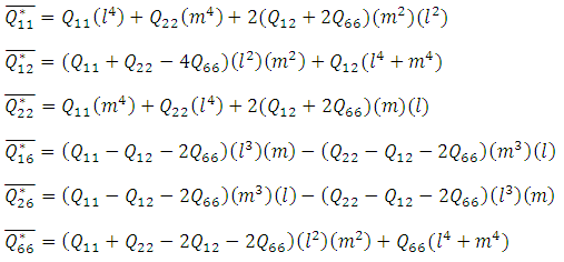
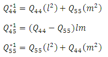
Classical lamination shell theory (CLST) is the simplest method used for the analysis of the shell structure. The most important lamination of classical lamination shell theory is that each ply is assumed to be in a state of plane stress and those transverse shear stresses were neglected. The constitutive relations for any layer in the shell are in equation (4). | (4) |
 In which
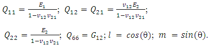 The general laminate Force-Deformation equations are defined in equation (5).
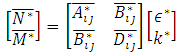 | (5) |
Where 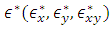 are mid-plane strains and
  are mid-plane curvatures and the laminate stiffness coefficients
  are defined as.
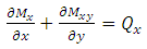
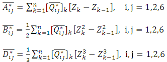 The governing equations of normal forces and bending moments may be derived by equation (6) and transverse shear forces may be derived by the moment equilibrium equations (7) & (8), when the composite pressure vessel is subjected to internal pressure P [1-9].
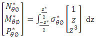 | (6) |
 | (7) |
 | (8) |
In which  are the symbols of circumferential and longitudinal directions.
  are unit normal forces along longitudinal, transverse directions and unit central shear force,
  are unit bending moments,
  are normal stresses and Z is thickness. From the equations (6), (7) & (8) Unit normal forces and normal transverse shear forces of laminated cylindrical shell and laminated hemispherical dome were derived to predict Strains along fiber direction and strains transverse to fiber direction, transverse shear strains and transverse shear stresses of fiber at 5 different locations on the composite pressure vessel. For a balanced symmetric laminates, Nxy=Mx=My=Mxy=0, The Bending-Extension coupling stiffness matrix [B] =0, Bend Twist coupling D16=D26=0, Shear-Extension coupling A16=A26=0. The analytical solutions of the composite Pressure vessel are obtained by using above equations and predicted strains were shown in figure 6.
4.2. First Order-Shear Deformation Shell Theory
First order-shear deformation shell theory (FOSDST) extends the kinematics of the classical lamination shell theory by including a gross transverse shear deformation in its kinematic assumptions; i.e., the transverse shear strain is assumed to be constant with respect to the thickness coordinate. As in CLST, FSDST also assumes each ply is in a state of plane stress condition but transverse shear stresses are not neglected. The constitutive relations for FOSDST were derived using lamina constitutive equations (4) and the equations (9).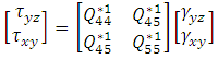 | (9) |
 In which
 The general laminate Force-Deformation equations for FOSDST are defined as in equation (5) and the laminate stiffness coefficients
  are defined as in CLST. In addition to CLST equations in FOSDST the Shear Force-Shear Deformation are defined as.
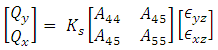 | (10) |
Where  The analytical solutions of the composite cylinder are obtained by using above equations and predicted strains were shown in figure 6, whereas transverse shear stresses and transverse shear strains were tabulated in table 4.
4.3. Third Order-Shear Deformation Shell Theory
Third order shear deformation shell theory (TOSDST) is based on the same assumptions as the Classical and First order shell theories, except that the assumption on the straightness and normality of a transverse normal after deformation by expanding the displacements as cubic functions of the thickness coordinate. The stress resultants are related to the strains by relations given in equation (11) & (12).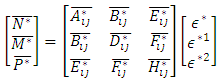 | (11) |
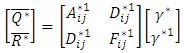 | (12) |
In which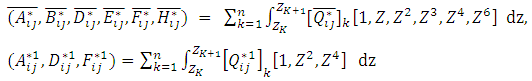 For Third order shear deformation shell theory,
  The analytical solutions of the composite Pressure vessel are obtained by using above equations 11, & 12 and predicted strains were shown in figure 6, whereas transverse shear stresses and transverse shear strains were tabulated in table 4.
5. Experimental Set-up
In this experimentation LDPE liner with polar bosses is developed on Injection Moulding Machine. As per the design given in Figure 3, the layers were wounded on the surface of the LDPE liner. After the development of the pressure vessel the entire shell is cured in an air circulating oven as per the curing cycle of the Epoxy LY556 & hardener HY5500 grade. The developed 50 bar capacity composite pressure vessel will be subjected to hydraulic test. The 3-Element Rectangular Rosette is used to obtain the longitudinal strain along fiber direction, strain transverse to the fiber direction and shear strain on the cylindrical portion, Whereas uniaxial rosettes are used on the dome portion to obtain the longitudinal strain along fiber direction only. The dome is having greater angle of winding compare with cylindrical portion as a result the helical thicknesses are also more. Because of the larger thicknesses the strains along transverse direction to the fiber and the shear strains were negligible. Hence uniaxial rosettes are used on the dome portion.
5.1. Hydraulic Testing
The water is filled in the pressure vessel by holding the test article inclined about 5°, with input dome at the bottom pit. Further the water is pumped into the test article from the input dome as shown in Figure 7. Venting tube is provided at the output dome for the air vents to move out. The data acquisition set up is arranged for automatic recording of strains.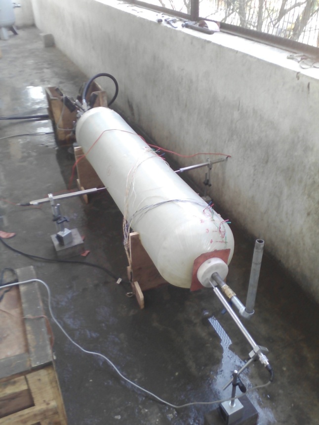 | Figure 4. Composite pressure vessel filled with water and subjected to hydraulic pressure for hydraulic test |
Strain-Smart is a ready-to-use, Windows-based software system for acquiring, reducing, presenting, and storing measurement data from strain gauges, strain-gauge-based transducers. Using the parameters input for sensors, materials, and instrumentation hardware, Strain-Smart automatically outputs the results of the test data in engineering units. The data acquisition setup is as shown in Figure 5. And the experimental results acquired from the Data acquisition setup were compared, validated and discussed by using Classical lamination shell theory, First order shear deformation shell theory, Third order shear deformation shell theory and Finite Element Method (FEM).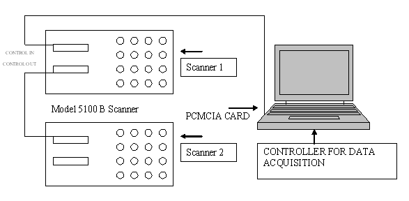 | Figure 5. Data acquisition setup |
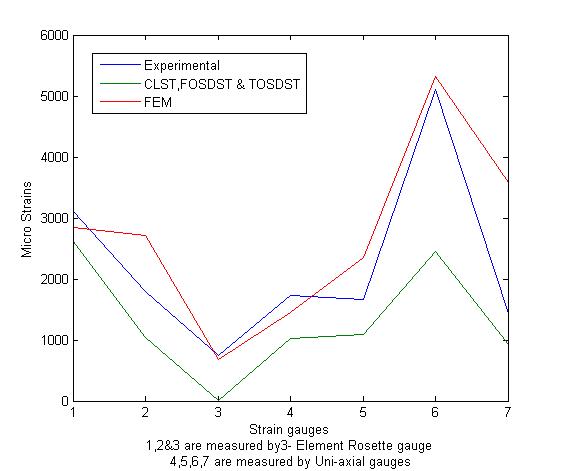 | Figure 6. Comparisons of Micro strains on different locations of Composite pressure vessel |
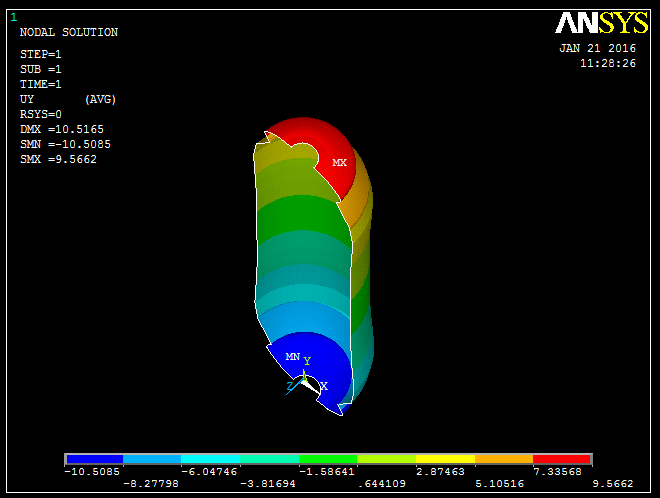 | Figure 7. Axial dilation of composite Pressure vessel at 50 bar pressure |
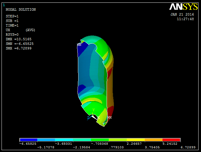 | Figure 8. Radial dilation of composite Pressure vessel at 50 bar pressure |
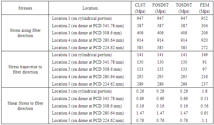
Table 2. Comparisons of stresses at different locations of Composite pressure vessel
 |
| |
|
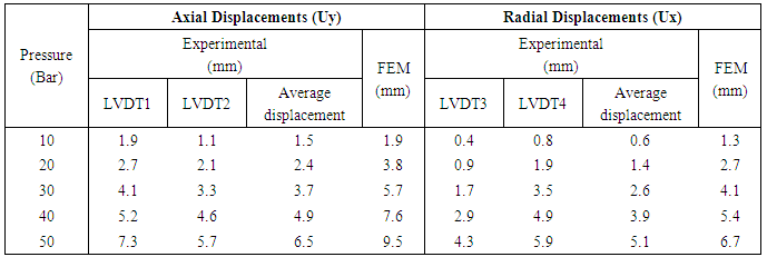
Table 3. Comparisons of Axial and Radial Displacements of Composite pressure vessel
 |
| |
|
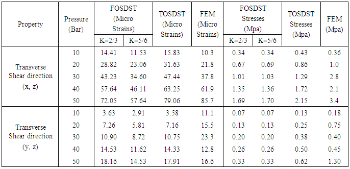
Table 4. Comparisons of Transverse Micro shear strains and Transverse shear Stresses of Composite pressure vessel at the junction of Cylinder and Dome
 |
| |
|
6. Results and Discussions
The micro-strains along fiber direction, micro-strains transverse to fiber direction and shear strains to fiber on cylindrical portion were measured by 3-Element Rectangular Rosette, the micro-strains along fiber direction on dome at four different locations were measured by uniaxial gauge and shown in figure 6 for the comparison of Experimental, CLST, FOSDST, TOSDST & FEM. By observing the figure 6, the micro-strains along fiber direction by using shear deformation theories shows 85% accuracy on cylindrical portion and 48% to 66% accuracy on dome portion, whereas FEM shows 91% accuracy on cylindrical portion and 40% to 95% accuracy on dome portion. And the micro-strains transverse to fiber direction by using shear deformation theories shows 58% accuracy and FEM shows 49% accuracy on cylindrical portion whereas micro shear strains by using shear deformation theories shows only 3% accuracy and FEM shows 91% accuracy with experimental results on cylindrical portion. The Stresses along fiber direction, stresses transverse to fiber direction and shear stress to fiber on cylindrical portion and on dome at 4 locations were predicted by CLST, FOSDST, TOSDST & FEM, and the results were tabulated in table 2.In finite element analysis, Ux represents the radial displacements and Uy indicates the axial displacements of the composite pressure vessel. The four LVDT (Linear Variable Displacement transducers) were used to measure the axial and radial displacements of a composite pressure vessel when subjected to pressure as shown in figure4. The measured displacements and displacements simulated by finite element analysis as shown in figure 7 & 8 were tabulated in table 3. To predict transverse shear strains and transverse shear stresses of the Composite Pressure vessel FOSDST, TOSDST and FEM were considered. In FOSDST two cases (shear correction factors K=2/3 and 5/6) were considered for the prediction of transverse shear strains and transverse shear stresses whereas TOSDST requires no correction factors. The predicted transverse shear strains and transverse shear stresses were tabulated in table 4.
7. Conclusions
The CLT and First-order shear deformation theory (FOST) generally provide an acceptable compromise between accuracy and economy in predicting the global responses of thin and relatively thin composite laminates. But these theories fail to give accurate results for the through- the- thickness stress response in regions of discontinuity such as cut-outs, holes, and boundaries. Moreover these theories require shear correction coefficients to rectify unrealistic variations of the shear strain/stress through the thickness. Because of the complexities, analytical solutions for the prediction of transverse/inter-laminar stresses exist for composite laminates with simple geometry, loading and boundary conditions. Therefore more emphasis has been placed on the use of numerical methods when the composite laminate problem involves complicated geometry, loading and boundary conditions. Among the various numerical techniques available, it is seen that the Finite element method is not only simple but straight forward for efficient programming and also versatile enough to cover all types of problems relevant to practical situations. The experimental Strains were validated by using Classical Laminated Shell Theory (CLST), First Order Shear Deformation Shell Theory (FOSDST), Third Order Shear Deformation Shell Theory (TOSDST) and Finite Element Method (FEM). By using FEM, TOSDST and FOSDST the transverse shear stresses and transverse shear strains are also predicted. The transverse shear force is one of the reason for de-lamination and failures at junctions, at pole openings and hoop-doily junctions. By predicting the transverse shear stresses and strains we can able to understand the failure criteria of the pressure vessel in transverse direction.The mathematical model developed for the composite pressure vessel is experimentally validated. The design is safe for the given design pressure of 50 bar where as the Composite Pressure Vessel was burst at 55.3 bar.
References
| [1] | J Raamachandran (2013) “Thin Shells Theory and Problems” Reprinted, Universities Press (India) Private Limited. |
| [2] | M. Madhavi, Dr K. V. J. Rao, Dr K. Narayana Rao (2009) “Design and Analysis of filament wound composite pressure vessel with integrated end domes”, Defense Science Journal, Vol 59, No.1, January 2009. |
| [3] | Cheol-Ung Kim, Ji-Ho Kang, Chang-Sun Hong, Chun-Gon Kim (2005) “Optimal design of filament wound structures under internal pressure based on the semi-geodesic path algorithm”, Composite structures 67 March (2005) 443-452. |
| [4] | J.N. Reddy (2004) “Mechanics of laminated composite plates and shells theory and Analysis”, second edition, CRC Press. |
| [5] | Nagesh (2003) “Finite-element Analysis of composite pressure vessels with progressive degradation”, Defense Science Journal, Vol 53, No.1, January 2003. |
| [6] | Cho-chung Liang, Hung-Wen chen, Cheng-Huan Wang, (2002), “Optimum design of dome contour for filament wound composite pressure vessels based on a shape factor”, Composite structures 58469-480. |
| [7] | Jae-Sung Park, Chang-Sun Hong, Chun-Gon Kim, Cheol-Ung Kim, (2002) “Analysis of filament wound composite structures considering the change of winding angles through the thickness direction”, Composite structures 55, 63-71. |
| [8] | R. Rikards, A. Chate, O. Ozolinsh (2001) “Analysis for buckling and vibrations of composite stiffened shells and plates”, Composite Structures, Vol. 51, pp. 361-370.(12) |
| [9] | X. HUANG, G. LU (2000) “Buckling analysis of laminated circular cylindrical shells using a two-surface theory” International Journal of Mechanical Engineering Education Vol 30, No 2, pp. 171–183.(10) |
| [10] | Katrici. N, “Design of fiber reinforced composite pressure vessels, M.S. Thesis, Middle East Technical University, Turkey, 1998. |
| [11] | Lin YC, Hwang WC, (1995) Design of dome contour for filament-wound rocket motor cases. Trans Aeronautical and Astronaut Soc.Republic of China (Taiwan) 1995:27(1):61-70. |
| [12] | B. Csonka and I. Kozák, Mota soares and C.A Mota soares (1995), “Shape optimization of axisymmetric shells using a higher-order shear deformation theory”, Structural Optimization 9, 117-127.(15) |
| [13] | S.T. Peters, W.D. Humphery, R.F. Foral, (1990), “Filament Winding Composite Structure Fabrication”, SAMPE. |
| [14] | Lossie, M and Brussel, H. Van, 1990, “Design Principles in filament winding”, Composites manufacturing, 5(1):5-13. |
| [15] | V.A. Bunakov, V.D. Protasov, (1989) “Composite Pressure Vessels,” Structures and Design, Hand book of Composites vol-2, Elsevier Science Publishers B.V. |
| [16] | I.F. Obraztsov, V.V. Vasil’e V, (1989) “Optimal Design of Composite Structures”, Structures and Design, Hand book of Composites vol-2, Elsevier Science Publishers B.V. |
| [17] | V. A. Bunakov, V. D. Protasov, (1989) “Composite Pressure Vessels,” Structures and Design, Hand book of Composites vol-2, Elsevier Science Publishers B.V. |
| [18] | T. Kant and M. P. Menon (1989) “Higher-order theories for composite and sandwich cylindrical shells with co finite element”, Computers and structures Vol. 33, No. 5, pp. 1191-1204.(5) |
| [19] | Fukunaga H. Uemura M. (1983) “Optimum design of helically wound composite pressure vessels”, Compos Struct 1:31-49, 1983. |
| [20] | New house N.L and Humphery. W.D, “Development of the standard test evaluation bottle (STEB)”, in: 17th National SAMPE Technical Conference, 1985, 554-62. |

 Abstract
 Reference
 Full-Text PDF
 Full-text HTML