-
Paper Information
- Paper Submission
-
Journal Information
- About This Journal
- Editorial Board
- Current Issue
- Archive
- Author Guidelines
- Contact Us
International Journal of Composite Materials
p-ISSN: 2166-479X e-ISSN: 2166-4919
2016; 6(3): 68-78
doi:10.5923/j.cmaterials.20160603.02

Parametric Study of Tri-axially Braided Composites
 Abstract
 Reference
 Full-Text PDF
 Full-text HTML
Mohamad Ismail, Ali Ismail, Mohammad Hammoud, Ali Hallal
Mechanical Department, School of Engineering, Lebanese International University, Beirut, Lebanon
Correspondence to: Ali Hallal, Mechanical Department, School of Engineering, Lebanese International University, Beirut, Lebanon.
| Email: |  |
Copyright © 2016 Scientific & Academic Publishing. All Rights Reserved.
This work is licensed under the Creative Commons Attribution International License (CC BY).
http://creativecommons.org/licenses/by/4.0/

In this paper, a parametric study of mechanical properties for tri-axially braided composite is presented. The main parameters involved are: the braid angle “θ”, the fiber volume fraction “Vf” and the fiber type. An analytical modeling is adopted to evaluate the 3D elastic properties and ultimate strengths. This model is based on a multi-scale homogenization method, the 3SHM (three Stages Homogenization Method) where Tsai-Wu and Christensen Failure criteria and a damaged stiffness model are used to predict the failure of composites. A validation of the analytical model is done by comparing the results with available experimental and numerical FE data. At the braid angle θ = 50°, and for different types of fibers and Vf, the composite is almost in-plane isotropic, where in-plane Young’s moduli and tensile strengths are equal. At this angle, the highest values of the in-plane shear modulus and shear strength are obtained.
Keywords: Fabrics, Textiles, Mechanical properties, Strength, Analytical modelling
Cite this paper: Mohamad Ismail, Ali Ismail, Mohammad Hammoud, Ali Hallal, Parametric Study of Tri-axially Braided Composites, International Journal of Composite Materials, Vol. 6 No. 3, 2016, pp. 68-78. doi: 10.5923/j.cmaterials.20160603.02.
Article Outline
1. Introduction
- Composites materials, and especially textiles, are taken more attention due to their mechanical properties. This paper presents a parametric study of the mechanical properties for a particular type of textile composites, the 2D tri-axially braided composite. As known, these types of fabrics are characterized by their braid angle and composed from two braided yarns and one axial yarn. Braided yarns make an angle that varies between zero and ninety degree; the common angles are 30, 45 and 60 degrees. Thus, a variety of braided composite architectures are found taking into account that different fiber volume fraction and fiber types can also be involved. The variation of these parameters leads to different mechanical properties of the material.The prediction of elastic properties and ultimate strengths of textile composites has been done using analytical and numerical Finite Element models. In Literature most of the studies focus on woven composites, plain weave, satin and Twill fabrics, however less studies are found for the braided fabrics. Byun et al. [1] studied a two-step braided composite by two analytical models: a micro-cell model and a macro-cell model. The micro-cell model presents an attempt to combine the iso-strain and iso-stress assumptions in assembling different laminates composing the REV (Representative Elementary Volume) using CLT (Classical Laminates Theory). At first, an iso-stress assumption is used along the axial direction and then, iso-strain assumption is used along the transverse direction. The macro cell model represents a volume averaging model using iso-strain assumption. Results for in-plane elastic properties compared to those experimental reveal that micro cell model yields better results for axial Young’s modulus and the in-plane Poisson’s ratio, while both models yield less accurate results for the axial shear modulus.A 3D iso-strain model is presented by Shokrieh and Mazloomi [2] to evaluate the stiffness of tri-axially braided composite. In this model, the composite is treated as a set of several layers representing braided and axial yarns. The stiffness of sinusoidal off-axis braided layers and axial layers are estimated using the layers fiber volume fraction equal to that of the REV. Then, the stiffness of the REV is obtained from averaging the stiffness matrices of the layers over their thickness fractions. They compared their results to those obtained from a stiffness “volume averaging” model and experimental data presented by Quek et al. [3]. Results show improvements in the prediction of the transverse Young’s modulus “Ey” and the in-plane shear modulus “Gxy”. Numerical finite element modeling is done for 3D tri-axially braided composites. Almost a good agreement is found for Young’s moduli while less agreement is found for axial shear modulus [4]. Fewer studies are found concerning the prediction of ultimate strengths [5-8]. Li [9] used the iso-strain model form modeling 3D braided composites. A good agreement with experimental results for axial Young’s modulus and tensile strength with an error not exceeding 10% when applied on 3D five directional braided composites. More recently, Jiang et al. [10] proposed a geometrical modeling, the helix model, and used the iso-strain model and Tsai-Wu failure criterion in order to evaluate the elastic properties and ultimate strengths of 3D braided composites. Axial Young’s modulus and ultimate strength are compared to experimental data where good agreement is shown. The main objective of this study is to investigate the influence on mechanical properties of braid angles, fiber volume fraction and the fiber type. Such kind of parametric study is beneficial for any engineer and designer that would use the optimum braided architecture for his design. It enables the selection of the appropriate braid angle, fiber volume fraction and fiber types that could fit the design requirements and tends to save the maximum weight. In the case of this study, the large number of investigated braided composites with their different architectures conducting to eliminate the experimental tests and numerical Finite Element modeling as a tool for evaluating mechanical properties. Moreover, the desired mechanical properties comports the all three dimensional properties, in-plane and out of plane properties, which makes the experimental and numerical evaluations almost impossible. Experimental tests will be very expensive in terms of money and time, while available numerical modeling will be time dependent and can’t afford all needed properties especially concerning ultimate strengths. Thus, an analytical modeling of the mechanical properties is adopted. The presented analytical model is originally developed and yet used for woven composites [11, 12].
2. Modeling
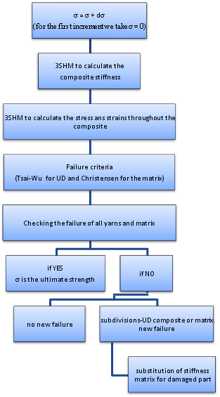
- The analytical model which provides the 3D elastic properties, ultimate strengths and the stress-strain diagrams for axial and shear loadings, is presented. The proposed analytical modeling is composed from a homogenization method, failure criteria and a damaged stiffness model as shown in Figure 1. A geometrical modeling relying on a sinusoidal modeling of the undulated yarns is adopted. Chamis micromechanical model [13, 14] is used to determine the elastic properties and ultimate strengths of subdivisions-UD composites. Then the analytical homogenization method developed by [11, 12] tends to predict the stiffness matrix of the composite and to evaluate the stress-strain fields throughout the composite. The fourth component of this model is the failure criteria, which is the Tsai-Wu failure criterion. The fifth component used is a damaged stiffness model for subdivisions-UD composites as shown in Figure 1.
 | Figure 1. General Scheme of the evaluation of the ultimate strength under static loading of textile composites Geometrical modeling |
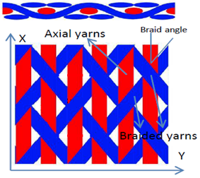 | Figure 2. REV for a 2D tri-axially braided composite |
 | (1) |
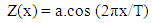
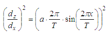
 | Figure 3. Sinusoidal shape of an undulated yarn |
 | (2) |
 | (3) |
 | (4) |
 and in each yarn
  is very important in determining the stiffness matrix of the composite. Thus, there are many analytical methods where
  could be determined, depends on available experimental data of the studied composite. Knowing that almost all experimental data of composites give the value of
  However,
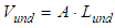
  can be calculated in terms of REV and yarns volumes:
 | (5) |
2.1. Analytical Homogenization Method (3SHM model)
- In this section, the homogenization method required to determine the elastic properties and composite stiffness matrix is briefly presented. Moreover, this method is used to predict the stress and strain fields throughout the REV “Representative Elementary Volume”. The homogenization method was developed earlier in order to predict the elastic properties of textile composites.Geometrical modeling is employed for the discretization of undulated yarns and the calculation of fibers orientations and sizes of sub-volumes. Concerning the homogenization method, the 3SHM model presents three stages of homogenization levels: micro, meso and macro homogenization stages. At the first stage, the stiffness matrices of sub-volumes are calculated. Then, at the meso homogenization stage the stiffness matrices of yarns are evaluated by assembling sub-volumes using a combined iso-strain and iso-stress method. Finally, at the macro stage, the stiffness of the REV is evaluated in terms of the homogenized yarns and the matrix stiffness matrices under an iso-strain assumption as shown in Figure 4.
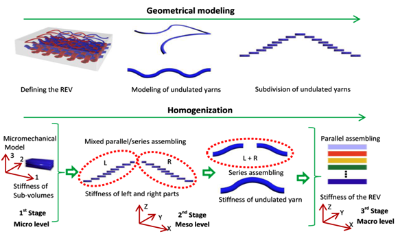 | Figure 4. The homogenization scheme of the 3SHM model |
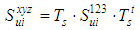
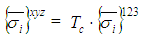
 are known in the local coordinate system (123) in terms of compliance matrix
 | (6) |
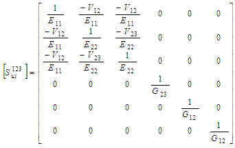 | (7) |
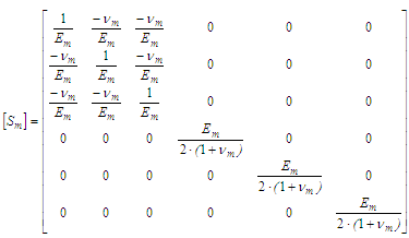
 is the compliance matrix of a transversely isotropic material.There are many analytical micromechanical models used to predict the elastic properties of unidirectional lamina with long fibers. Some micromechanical models are also used to evaluate the ultimate strength of UD composites. Based on a comparative study done previously [15], the Chamis micromechanical model [13, 14] is used to evaluate the elastic properties and ultimate strength for a UD composite.The matrix is considered to be an isotropic material where the stiffness matrix
  can be simply derived from the compliance matrix
  in terms of Young’s modulus
  and the Poisson’s ratio
 | (8) |
 | (9) |
 | (10) |
 and
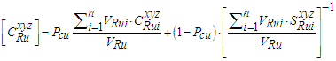
and  are the 3D transformation matrices.2- The sub-volumes of left and right undulated parts (referred by L and R respectively) as shown in Figure 5 are assembled in a mixed iso-strain /iso-stress model using a weighted parameter
  , where the stiffness matrices of left and right undulated parts are given respectively by:
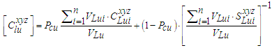 | (11) |
 | (12) |
 | (13) |
 Volume of the ith sub-volume of the left undulated part
 Volume of the ith sub-volume of the right undulated part
 Volume of the left undulated part
 Volume of the right undulated part
 The mean value of the inclination angle of sub-volumes
  of a subdivided undulated yarn. Noting that in general and due to the symmetry of left and right undulated parts, we have:
 has the same value for both parts. The yarn is composed of homogenized left and right undulated parts which form a series system when assembled along undulation direction as shown in Figure 5.
  | Figure 5. (a) Parallel system, (b) series system, (c) sub-volumes of actual undulated yarn |
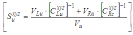 | (14) |
 | (15) |
 is the volume of the yarn.At the macro level homogenization stage, the stiffness of the REV is evaluated in terms of the previously evaluated stiffness matrices of the matrix and the n yarns. Therefore, the composite is treated as n+1 homogenized block assumed to represent a parallel system and assembled under an iso-strain condition:
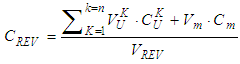 | (16) |
 and
and  are the volumes of the matrix and the REV, respectively.
2.2. Evaluation of the Stress-strain Fields throughout the Composite
- In order to apply the failure criterion and the damaged stiffness model, the stress and strain fields for each subdivision-UD composite should be calculated. This could be done using the 3SHM model. An inverse procedure of that used to determine the elastic properties is applied. Let us consider a textile composite which consists of n yarns and a polymeric matrix. The generalized homogenization method (3SHM), allows the calculation of stress and strain fields throughout the composite as follows:The average stress tensor throughout the composite is given by:
 | (17) |
 | (18) |
 is the stiffness matrix of the compositeThe iso-strain conditions gives:
 | (19) |
 and
and are the average strain in the composite and the n yarns and matrixThe stress throughout the matrix is given by:
 | (20) |
 is the stiffness matrix of the matrixThe stress throughout the n yarns is given by:
 | (21) |
 is the stiffness matrix of the ith yarnThen, the stress throughout each subdivision of each yarn should be calculated as follow:An iso-stress condition is considered for the left and right parts of the undulated yarns:
 | (22) |
 | (23) |
 is the compliance matrix of the ith yarn
 | (24) |
 and
and  are the average strains in the undulated right/left part of the ith yarn.
 | (25) |
 and
and  are the stress, strain and the stiffness matrix respectively of the ith yarn under iso-stress condition
 | (26) |
 | (27) |
 | (28) |
2.3. Failure Criteria for Subdivision-UD Composite and Matrix
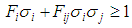
- The failure criterion proposed to predict the failure of UD composites is a tensor polynomial criterion proposed by Tsai and Wu [12]. This criterion is used for subdivision-UD composite and straight yarns. This criterion may be expressed in tensor notation as:
 | (29) |
 | (30) |
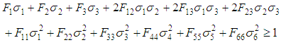 | (31) |
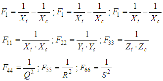 Where Xt, Xc, Yt, Yc, Zt and Zc are the ultimate axial strengths for UD composites calculated by Chamis model [13, 14], where t is for tensile and c for compression in x, y and z directions. Also, Q, R and S are the ultimate shear strengths for UD composites, where Q and R are for out of plane shear and S is for in-plane shear.Concerning the failure of the pure matrix, the Christensen’s failure criterion is adopted as follows:
 | (32) |
 is the maximum tensile stress at a point which is the maximum value of the three roots of the following cubic equation:
 | (33) |
2.4. Damaged Stiffness Model for UD Composites and Matrix
- The damaged stiffness model tends to replace the stiffness of UD composites or the matrix at failure by a reduced stiffness matrix. The complete failure of a subdivision-UD composite could happen under different failure modes. As discussed, in recent works, the method used is based on determining the major loading that causes the failure, and then assigning a corresponding failure mode in order to replace the stiffness of UD composites by a specific damaged stiffness matrix related to that failure mode. However, assigning one failure mode for each damaged subdivision-UD composite could lead to huge errors due to the modeling of textile composites with complex undulated yarns. In order to overcome this problem the influence of all stresses acting on a UD composite is taken into account. Different failure modes should be considered. The failure modes, as given by [18], consist of: Tensile and compressive axial failure modes along x, y and z direction, and shear failure modes for both positive and negative applied shear stress. The failure modes are shown in Figure 6:
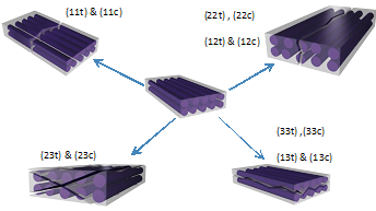 | Figure 6. Failure modes |
 and
and 
2.5. Damaged Stiffness Model
- Hereafter the following ratios and the reduced elastic properties
 (ratio of stresses along x direction)
 (ratio of stresses along x direction)
 (ratio of stresses along y direction)
 (ratio of stresses along y direction)
 (ratio of stresses along z direction)
 (ratio of stresses along z direction)
 (ratio of in-plane (xy) shear stresses for positive applied shear);
  (ratio of in-plane (xy) shear stresses for negative applied shear)
 (ratio of in-plane (xz) shear stresses for positive applied shear);
  (ratio of in-plane (xz) shear stresses for negative applied shear)
 (ratio of in-plane (yz) shear stresses for positive applied shear);
  (ratio of in-plane (yz) shear stresses for negative applied shear)Axial tensile stress failure mode (11t):
  Axial compressive stress failure mode (11c):
  Transversal tensile stress failure mode (22t):
  and
and  Transversal compressive stress failure mode (22c):
  Transversal out of plane tensile stress failure mode (33t):
  and
and  Transversal out of plane compressive stress failure mode (33c):
  Positive in-plane shear stress failure mode (12t): same as failure mode (22t).Negative in-plane shear stress failure mode (12c): same as failure mode (22c).Positive in-plane shear stress failure mode (13t): same as failure mode (33t).Negative in-plane shear stress failure mode (13c): same as failure mode (33c).Positive in-plane shear stress failure mode (23t):
 and
and  Negative in-plane shear stress failure mode (23c):
 and
and 
3. Results and Discussion
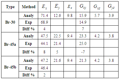
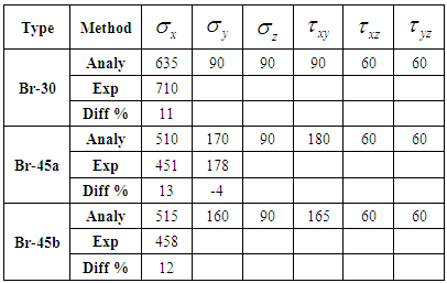
- First of all, the model is validated through a modeling of tri-axially braided composite [19] found in literature. A good agreement is found between the elastic properties and ultimate strengths where the error is less than 10% as shown in Tables 1 and 2. The elastic moduli are in GPa and the strengths are in MPa.
|
|
|
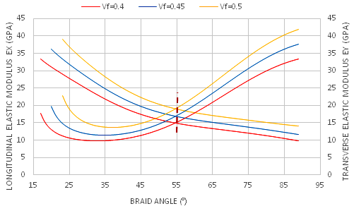
 decreases with the increment of the braid angle. The transversal Young’s modulus
  increases with the increment of the braid angle. This is due to the increment of the rigidity in the y-direction and its decrement in the x-direction. In addition, the transversal and axial Young’s moduli intersect at the braid angle θ = 56° for all fraction volumes, which means that the composite will behave as an isotropic material, knowing that the AS4 carbon fiber is an anisotropic material.
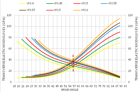 | Figure 7. Effect of the braid angle on in-plane Young’s modulus ( and and  ) for different fraction volume ) for different fraction volume  for the AS4 carbon fiber for the AS4 carbon fiber |
 | Figure 8. Effect of the braid angle on in-plane Young’s modulus ( and and  ) for different fraction volume ) for different fraction volume  for the S2-glass fiber for the S2-glass fiber |
 , increases with the increment of the braid angle and reaches its peak at θ = 47°, in all fraction volumes. This is due to the braided yarns that reinforce the in-plane shear modulus by preventing sliding between yarns. In addition, it is observed that between the angles 40° and 50°, the highest range of
  is obtained. For the S2 glass as shown below in Figure 10, the in-plane shear modulus
  , increases with the increment of the braid angle and reaches its peak at θ = 47⁰, in all fraction volumes.
 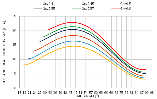 | Figure 9. Effect of the braid angle on in-plane shear modulus for different fraction volume for different fraction volume  for the AS4 carbon fiber for the AS4 carbon fiber |
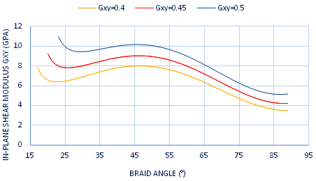 | Figure 10. The effect of braid angle on in-plane shear modulus  for different fraction volume for different fraction volume  for the S2-galss for the S2-galss |
 is higher than the other Poisson’s ratios at θ ≤ 45°, as shown in Figure 11. Where, the reinforcement of the braided yarns in the axial direction is larger than in the y-direction at θ ≤ 45°. This means, that the dilatation in the lateral direction in this range is higher than the axial direction, which is relatively small. Moreover, the other Poisson’s ratios
  and
and  are nonlinearly varying with the increment of the braid angle.
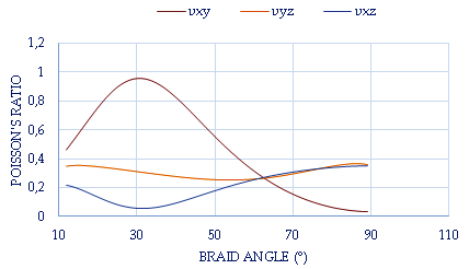 | Figure 11. Effect of the braid angle on Poisson’s ratio () for fraction volume  = 0.35 for the AS4 carbon fiber = 0.35 for the AS4 carbon fiber |
 increases from 0.3 to 0.6 in AS4 carbon fiber. This means that the Poisson’s ratio depends on the braid angle only. To improve this conclusion, Figure 12 also shows the in-plane Poisson’s ratio for S2-glass which is an isotropic material and has the same behavior for the same range of angles. There is no significant change in the Poisson’s ratio as the fraction volume
  increases from 0.4 to 0.5, but there is a difference in the maximum values of the Poisson’s ratio between AS4 carbon fiber and S2-glass which must effectively depends on the material properties.
 | Figure 12. Effect of the braid angle on the in-plane Poisson’s ratio  for different fraction volume for different fraction volume  for both AS4 carbon fiber and S2-glass for both AS4 carbon fiber and S2-glass |
 which decreases with the increment of the braid angle, while the transversal strength
  increases with the increment of the braid angle. This is due to the increment of the rigidity in the y-direction as a result of the increment of the braid angle. In addition, the transversal and axial strengths intersect between the braid angle θ = 62⁰ and θ = 67⁰ as the fraction volumes change from 0.35 to 0.6.
 | Figure 13. Effect of the braid angle on in-plane tensile strength ( and and ) for different fraction volume ) for different fraction volume  for the AS4 carbon fiber for the AS4 carbon fiber |
 which decreases with the increment of the braid angle, while the transversal strength
  increases with the increment of the braid angle. In addition, the strengths of S2 glass do not intersect between the transversal and axial strengths, due to the isotropic behavior of the fibers. Therefore, as a conclusion, the effect is dual, depending on the fibers’ material and the geometry. However, in the modulus of elasticity, it was the effect of geometry only.
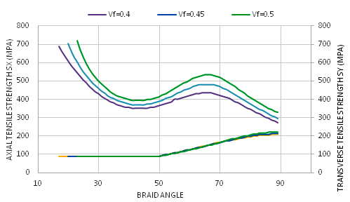 | Figure 14. Effect of the braid angle on in-plane tensile strength ( and and ) for different fraction volume ) for different fraction volume  for the S2-glass for the S2-glass |
 for AS4 carbon fiber, which increases with the increment of braid angle, and reaches its peak between θ = 45⁰ and θ = 52⁰ in all fraction volumes. This is due to the braided yarns that reinforce the in-plane shear strength by preventing sliding between yarns.
  | Figure 15. Effect of the braid angle on in-plane shear strength  for different fraction volume for different fraction volume  for the As4 carbon fiber for the As4 carbon fiber |
 is independent of the material of the fibers and the effect is related to the geometry where the maximum still between the angles θ = 45⁰ and θ = 52° in all cases.
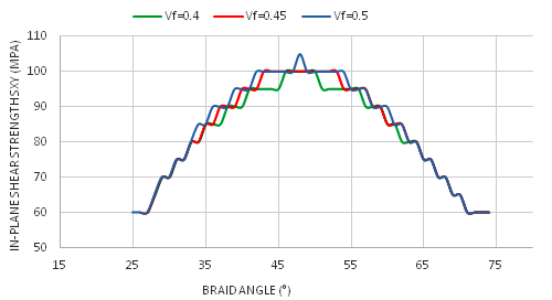 | Figure 16. Effect of the braid angle on in-plane shears strength  for different fraction volume for different fraction volume  for the S2-glass for the S2-glass |
4. Conclusions
- The proposed model consists of four main parts: a micromechanical modeling for elastic properties and ultimate strengths for unidirectional composites (UD composites), a homogenization method at meso and macro levels to determine the composite stiffness and stress-strain fields throughout the composite, two 3D failure criteria for the matrix and UD composites and a damaged stiffness model. At first, a modeling of some tri-axially braided composites is performed where the predicted elastic properties and ultimate strengths are compared to available experimental data and numerical Finite element predictions. After validating the reliability of the analytical model, a parametric study is done. The obtained results are analyzed in order to investigate the influence of each parameter (Fiber type,
 and braid angle) on the mechanical properties of braided composites. Some significant remarks are found; at specific angle for different type of fibers and different values of
  the in-plane Young’s moduli are similar. In addition, at a closer angle the highest values of in-plane shear modulus and shear strengths are found. The analysis shows clearly how the influence of the braid angle could be significant. It also shows that for some high value of
  the improvement in mechanical properties especially ultimate strengths is not so important. As a conclusion, this work proposed a parametric study based on analytical modeling which leads to a better choice of braided fabric architecture to achieve the optimum design of a composite structure. Also, it shows that the same study could be done for any kind of fiber reinforcement and polymeric matrix providing a data sheet for engineers and designers.