-
Paper Information
- Paper Submission
-
Journal Information
- About This Journal
- Editorial Board
- Current Issue
- Archive
- Author Guidelines
- Contact Us
International Journal of Composite Materials
p-ISSN: 2166-479X e-ISSN: 2166-4919
2016; 6(1): 26-33
doi:10.5923/j.cmaterials.20160601.04

Eigen Value Buckling Analysis of Thin FRP Cross Ply 4-Layered Hexagonal Cut on Rectangular Laminated Composites
 Abstract
 Reference
 Full-Text PDF
 Full-text HTML
S. Mahesh Babu 1, M. Venkateswara Rao 2
1SRK Institute of Technology, Vijayawada, India
2Bapatla Engineering College, Bapatla, Guntur, India
Correspondence to: S. Mahesh Babu , SRK Institute of Technology, Vijayawada, India.
| Email: |  |
Copyright © 2016 Scientific & Academic Publishing. All Rights Reserved.
This work is licensed under the Creative Commons Attribution International License (CC BY).
http://creativecommons.org/licenses/by/4.0/

The present research work is to evaluate the buckling load of thin FRP symmetric cross ply rectangular laminates (00/900/900/00) with hexagonal cut out, which is subjected to uniaxial compression using finite-element method software ANSYS. The analysis is done using ANSYS 12.0. The buckling load is evaluated by changing the parameters such as hole orientation (β), aspect ratio (a/b), thickness ratio (S), number of layers (N) and boundary conditions. The effects of these five parameters are studied on buckling load. The result shows that the buckling load is more at β =600 and minimum at β = 300, decreases with the increase in an aspect ratio (a/b), decreases with an increase in the thickness ratio (S), increases from N=4 to N= 12 and remains constant up to N=20 and finally more in clamped-clamped (C-C) boundary condition when compared to clamped-simply supported (C-S) and simply-supported simply-supported (S-S) boundary conditions.
Keywords: FRP, FEM, Buckling analysis, Uniaxial load, ANSYS, Cross-ply
Cite this paper: S. Mahesh Babu , M. Venkateswara Rao , Eigen Value Buckling Analysis of Thin FRP Cross Ply 4-Layered Hexagonal Cut on Rectangular Laminated Composites, International Journal of Composite Materials, Vol. 6 No. 1, 2016, pp. 26-33. doi: 10.5923/j.cmaterials.20160601.04.
Article Outline
1. Introduction
- The buckling of rectangular plates was subject of more than a century. Exact and approximate solutions for rectangular plates have been developed. There were many exact solutions for linear elastic isotropic thin plates; many treated by Timoshenko [1]. M. Tajdari et al [2] investigated the effect of plate support conditions, aspect ratio and hole size on the buckling strength of perforated plates subjected to linearly varying load. They used FEM software ANSYS to solve their problem. They concluded that increasing the hole size does not necessarily reduce the buckling strength of the perforated plates. For certain aspect ratios and support conditions buckling strength increases with increase in hole size. And they also concluded that clamped boundary condition increases the buckling strength of the plate when compared to simply-supported and free boundary conditions.J. Purbolaksono and M.H. Aliabadi [3] were presented the buckling analysis of the perforated thin plates by the dual reciprocity boundary element method (DRBM). The plate buckling equations of this method were presented as a standard eigen value problem. They evaluated the simply-supported rectangular plates with different locations of a circular hole subjected to compressive load and FEM results were presented for comparison. They concluded that buckling co-efficient for the plate with a circular hole would decrease as the distance of the center of circular hole to the central of the plate increased. Muhammed D. Tekin and M. Fatih Altan [4] investigated the buckling load of simply-supported reinforced rectangular plate with circular hole and without hole subjected to uniaxial compression. They implemented this problem into FORTRAN. They concluded that bending stiffness decreases with increase in diameter of the hole.Ehaled M. EI-Sawy and Aly S. Nazmy [5] were introduced the effect of aspect ratio on the elastic buckling of uniaxial loaded plates with eccentric holes. The finite element method has employed to determine the buckling of load of uniaxial loaded rectangular perforated plates along four simply-supported edges with length of ‘a’ and width ‘b’. They concluded that rectangular hole with curved corners with its short dimension positioned along the longitudinal direction of the plate was better option compared to circular hole and also concluded that distance between the edge of the circular hole and nearest unloaded edge of the plate not less than 0.1b.Ibearugbulem et al [6] presented the buckling analysis of uniaxial compressed rectangular thin plate along the four simply-supported edges using Taylor-Mclaurin shape function. This study was accomplished through a theoretical formulation based on Taylor-Mclaurin’s series and application of Ritz method. The resulting critical load was found in the function of co-efficient ‘H’. They concluded that the values of ‘H’ were compared with the exact values within the range of aspect ratio from 0.1 to 1.0 and maximum percentage difference was found to be 0.098% for aspect ratio of 0.1while the least percentage difference was found to be 0.05% for an aspect ratio of 1.0. Hence, Taylor-Mclaurin’s series function was obtained for the SSSS plate was very good approximation of the exact shape function for the plate.Sandeep Singh et al [7] induced the buckling analysis of thin rectangular plates with circular cut outs subjected to partial edge compression using FEM. They were concluded that the buckling strength of the square plate is highly influenced by the partial edge compression, as compared to plate subjected to uniform edge compression. Hence, the influence of partial edge compression on plate, buckling load decreases with increase in aspect ratio. Umar Farooq & Karl Gregory [8] were investigated the computational modeling of pseudo-damage influenced buckling of fibrous composite panels. They studied and developed the mathematical formulation for buckling of laminated structure. This was implemented in the standard finite element code (Pro-Engineer/Mechanical). The damages equivalent to areas under impactor’s tips. They showed the results that damaged induced at the center of the plate significantly reduced the compressive strength of the structure and the diameter of the damage increases, buckling load decreases. Ashokkumaar. A [9] was presented a paper on buckling analysis of perforated rectangular plates with circular and square cuts at the center of the plate. He studied the effect of plate-support conditions, aspect ratio, hole geometry and hole size on the buckling strength of the perforated plates. He concluded that clamped-clamped boundary condition increases the buckling strength rather than simply-supported condition, at large hole sizes, the square hole cases had higher buckling strength than the respective circular hole case and finally, buckling load decreases with increase in aspect ratio. S. Mahesh Babu et al [10] investigated the buckling analysis of thin FRP composites with pseudo-damage at the center of the plate using FEM software ANSYS. They were evaluated by varying the boundary conditions, aspect ratio and thickness ratio. Finally, they found that buckling strength is more at clamped- clamped, when compared to clamped-simply supported and simply supported-simply supported, buckling load decreases with increase in thickness ratio and aspect ratio. S. Mahesh Babu et al [11] were presented a paper on buckling analysis of thin FRP composites using FEM software ANSYS. This model was evaluated by changing the support conditions, thickness ratio and number of layer. They concluded that buckling load is more in clamped-clamped boundary condition, decreases with increase in thickness ratio and number of layer. J. Leela Krishna et al [12] were predicted that linear buckling anlysis of thin FRP rectangular laminates with circular cut out under biaxial compression. This problem was evaluated by varying the hole position, aspect ratio and thickness ratio. They concluded that buckling load is more at top positioned hole, decreases with in aspect ratio and thickness ratio. Alidrasi [13] was presented a paper on the effect of imperfection on buckling load of perforated steel plate under uniaxial compression. He found buckling load of steel rectangular plates with circular and square cut outs by using numerical and experimental methods. He concluded that rectangular plate with circular cut has more buckling load when compared to the plate with square cut for same area of cut. I took as reference paper and extended it to hexagonal cut.
2. Problem Statement
- The objective of the paper is to determine the buckling load of thin FRP rectangular laminates with hexagonal cut out subjected to in-plane compression by changing the hole orientation (β), aspect ratio (a/b), thickness ratio (S), number of layers (N) and boundary conditions.
3. Geometrical Modeling
- A rectangular plate of length (a) is in X- axis direction, width (b) in Y- axis direction and thickness (t) in Z- axis direction. The length of the plate (a) is taken as 100mm, 150mm, 200mm and 250mm. The width of the plate (b) is 50mm, which is fixed in all cases. The side of the hexagon is 10mm. Then the corresponding a/b ratios are 2, 3, 4 and 5. Thickness of the plate is found from the length to thickness ratio (S) that is varied from 20, 40, 60, 80 and 100. And finally the number of layer (N) is varied from 4, 8, 12, 16 and 20. Modeling includes element type, real constants, and material properties, modeling of rectangle with cut and meshing. In the present study, shell linear 99 is selected as an element type, which is suitable for analyzing thin to moderately thick structures and well suited for linear, large rotation and large strain nonlinear applications. Fig. 1 shows the cross ply FRP rectangular four layered laminate with hexagonal cut out under uniaxial compression.
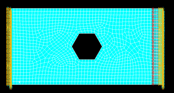 | Figure 1. FE model (clamped-clamped boundary condition, a/b=2, S=100, N=4 and β=0⁰ are taken in the above model) |
3.1. Validation of FE MODEL
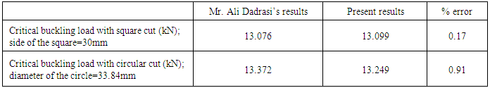
- The present finite model is validated from Ali Dadrasi. He was chosen a problem that effect of imperfection on buckling load of perforated rectangular steel plates and S8R5 as an element type. Dimensions of the plate, 150X100X2.07 mm3. The material properties are E=218GPa and µ=0.33.The results obtained from the present work have been validated with the comparative results in Table 1. From these comparison studies, it is concluded that results validated the correctness of the formulation.
|
3.2. Material Properties
- The following material properties are considered for the present analysis.i) Young’s moduli, E1=147E3 MPa, E2=10.3E3 MPa, and E3=10.3E3 MPaii) Poisson’s ratio, µ12=0.27, µ23=0.54 and µ31=0.27 andiii) Rigidity moduli, G12=7E3 MPa, G23=3.7E3 MPa and G31=7E3 MPa
4. Results and Discussion
4.1. Effect of Boundary Conditions
- Variation of buckling load with respect to mode number for different boundary conditions such as clamped-clamped, clamped-simply supported and simply supported- simply supported boundary conditions as shown in Fig. 2. By observing the graph, buckling load increases from mode 1 to mode 5 for each curve. In C-C boundary condition, laminates offers more resistance to deform when compared to C-S and S-S conditions.
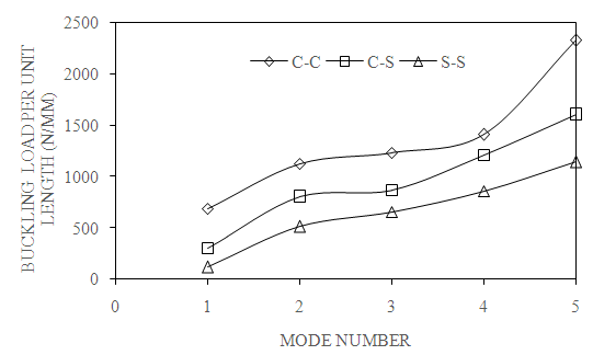 | Figure 2. Effect of boundary conditions on first five modes of buckling load (β=0⁰, a/b=2, N=4 and S=100) |
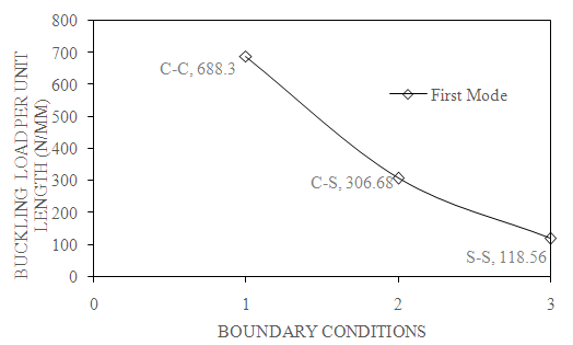 | Figure 3. Effect of boundary conditions on first mode of buckling load (β=0⁰, a/b=2, N=4 and S=100) |
4.2. Effect of Hole Orientation (β)
- Fig. 4 shows the variation of buckling load with respect to mode number for different hole orientations. Buckling load increases gradually with increase in mode number from mode 1 to mode 5 for different angles of hole orientations. The reason is that as mode number increases, the number of curvatures with in the span of the plate increases and each span acts as short span of the plate their by increasing the resistance towards deformation and resulting in higher value of buckling load.
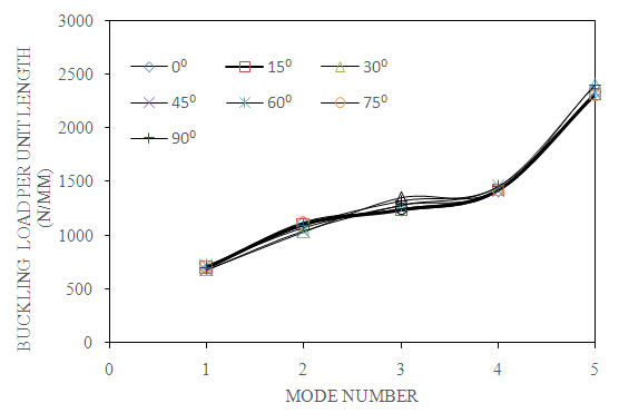 | Figure 4. Effect of hole orientation on first five of buckling load (C-C, a/b=2, N=4 and S=100) |
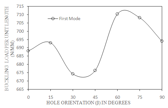 | Figure 5. Effect of hole orientation on first mode of buckling load (C-C, a/b=2, N=4 and S=100) |
4.3. Effect of Aspect Ratio (a/b)
- Fig. 6 shows the variation of buckling load with respect to mode number for different aspect ratios. As mode number increases from mode 1 to mode 5, increases the buckling load.
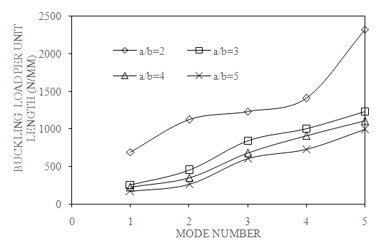 | Figure 6. Effect of aspect ratio on first five modes of buckling load (C-C, β=0⁰, N=4 and S=100) |
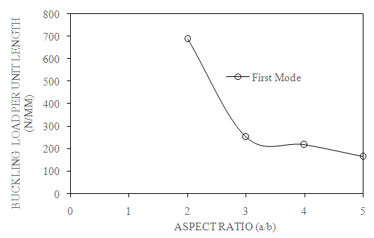 | Figure 7. Effect of aspect ratio on first mode of buckling load (C-C, β=0⁰, N=4 and S=100) |
4.4. Effect of Thickness Ratio (S)
- The graph is plotted between buckling load as an abscissa and mode number as ordinate for different thickness ratios as shown in Fig. 8. Buckling load increases gradually from mode 1 to mode 5. Therefore, with increase in mode number, increases the buckling load.
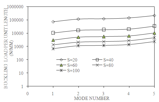 | Figure 8. Effect of thickness ratio on first five modes of buckling load (C-C, a/b=2, N=4 and β=0⁰) |
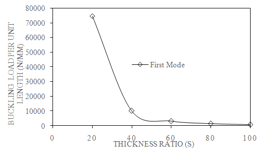 | Figure 9. Effect of aspect ratio on first mode of buckling load (C-C, a/b=2, N=4 and β=0⁰) |
4.5. Effect of Number of Layers (N)
- The change of buckling load with respect to mode number as shown in Fig. 10. As mode number increases, buckling load also increases. From the graph, it is mention that buckling load increases from mode 1 to mode 5 for different layers.
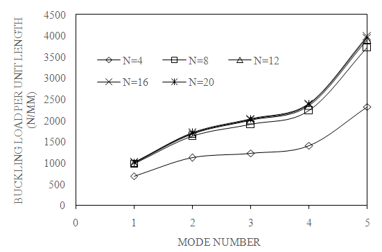 | Figure 10. Effect of number of layers on first modes of buckling load (C-C, a/b=2, S=100 and β=0⁰) |
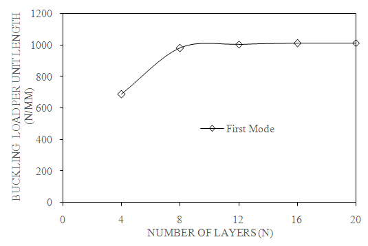 | Figure 11. Effect of number of layers on first mode of buckling load (C-C, a/b=2, β=0⁰ and S=100) |
5. Conclusions
- The results show that • Buckling load is maximum when hole orientation is at β =600 and minimum at β = 300, • Buckling load decreases with increase in aspect ratio (a/b), • Buckling load decreases with increase in thickness ratio (S), • Buckling load increases from N=4 to N= 12 and remains constant up to N=20 and• Finally, buckling load more in clamped-clamped boundary condition when compared to clamped-simply supported and simply-supported simply-supported boundary conditions.• The important significance of the paper is that this can reduces the complicated design in aerospace, navel etc, there by the weight of the system is reduces.