S. W. Chung1, S. M. Park2
1School of Architecture, University of Utah, Salt Lake City, USA
2Yeung Nam University, Tae Gu, Korea
Correspondence to: S. W. Chung, School of Architecture, University of Utah, Salt Lake City, USA.
| Email: |  |
Copyright © 2016 Scientific & Academic Publishing. All Rights Reserved.
This work is licensed under the Creative Commons Attribution International License (CC BY).
http://creativecommons.org/licenses/by/4.0/

Abstract
We will start with generalized Hook’s law of a three dimensional anisotropic body which is subjected to 6 different stresses and strains together with 21 elastic coefficients. Applying equilibrium and stress displacement equations and non-dimensionalize all the variables before asymptotically expanding, we are allowed to perform the asymptotic integration process which will derive the first approximation theory of an anisotropic cylindrical shell. The theory is valid for anisotropic non-homogeneous materials, which can be applied to layered walls of cylindrical shells with different materials. A choice of small length scale allows a system of differential equations accurately formulated for different loading and boundary conditions. The derived differential equations of homogeneous isotropic material are equivalent to classical theory.
Keywords:
Three Dimensional Anisotropic Element, Non-Homogeneous Anisotropic Materials, Generalized Hook’s Law, Boundary Layer, Asymptotic Integration, Classical Shell Theory
Cite this paper: S. W. Chung, S. M. Park, A Shell Theory of Hybrid Anisotropic Materials, International Journal of Composite Materials, Vol. 6 No. 1, 2016, pp. 15-25. doi: 10.5923/j.cmaterials.20160601.03.
1. Introduction
The use of composite materials have been wide spread over last 15 years from the aerospace vehicles to civil engineering structures, the materials possess such characteristics as high strength/density and properly controllable modulus/density ratios and they are generally composed of filaments and matrix materials. The filaments are embedded in the matrix materials to give additional stiffness and high strength.The cylindrical shell theory that we develop in this article is common to liquid oxygen storage tanks of outer space rockets, orbital shuttles as well as columns of building structures. The cylindrical coordinate system is shown in Figure 1.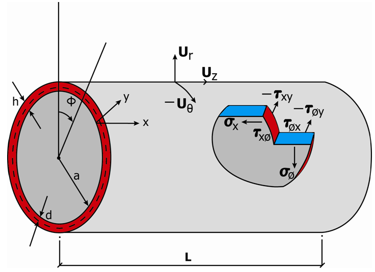 | Figure 1. Dimensions, deformations and stresses of a cylindrical shell |
As shown in Figures 2 and 3 the filaments can be arranged arbitrarily to make a composite structure more resistant to loadings. As the mechanical properties of composites vary depending on the direction of the fiber arrangement, it is necessary to analyze them by use of an anisotropic theory. Composite materials are also generally constructed of thin layers, which may have different thickness and different cross-ply angles. The cross-ply angle, ɣ, is the angle between major elastic axis of the material and reference axis (see Figures 2 and 3). The variation in properties in the direction of the thickness implies non-homogeneity of the material and composite structures must thus be analyzed according to theories, which allow for non-homogeneous anisotropic material behavior. Our task is to formulate theories for a shell of composite materials, which are non-homogeneous and anisotropic, or hybrid anisotropic materials.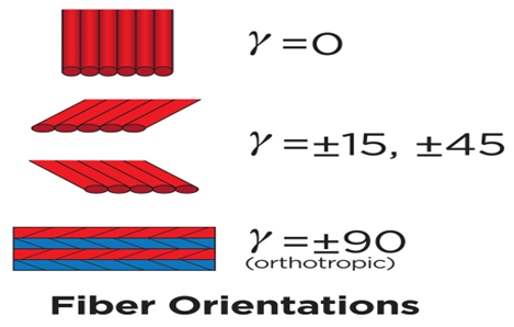 | Figure 2. Fiber orientation |
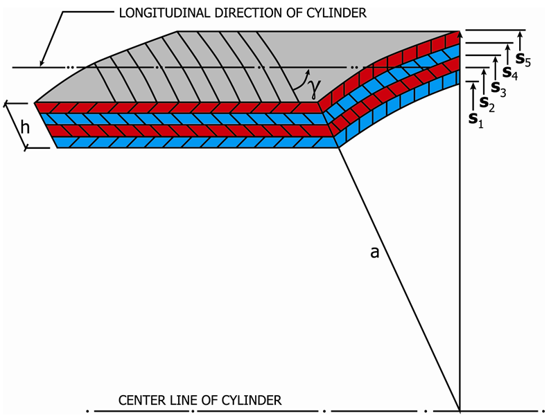 | Figure 3. A laminated cylindrical shell, material orientation ɣ |
According to the exact three-dimensional theory of elasticity, a shell element is considered as a volume element. All possible stresses and strains are assumed to exist and no simplifying assumptions are allowed in the formulation of the theory. We therefore allow for six stress components, six strain components and three displacements. There are thus fifteen unknowns to solve for in a three-dimensional elasticity problem. On the other hand, three equilibrium equations and six strain displacement equations can be obtained for a volume element and six generalized Hook’s law equations can be used. A total of fifteen equations can thus be formulated and it is possible to set up a solution for a three-dimensional elasticity problem. It is however very complicated to obtain a unique satisfaction of the above fifteen equations and the associated boundary conditions. This led to the development of various theories for structures of engineering interest. A group of simplifying assumptions that provide a reasonable description of the behavior of thin elastic shells proposed by Love (Reference [1]) has led to the development of the classical shell theories.Love’s theory is based upon the well-known hypotheses of thin shell theory. A detailed description of classical shell theory can be found in various articles. (References [2] to [6]). The system of shell equations derived based on the assumptions is usually regarded as satisfactory for thin homogenous, isotropic shells except for problems associated with certain types of loadings and where the transverse stresses and strains may be important. For example, the transverse stresses are of importance in the so-called near edge zone of a constrained cylindrical shell under internal pressure and for a shell made of very soft material in transverse direction. This led to an examination of the classical theory of interest and numerous investigators have tried to obtain more refined theories of shells.Another way of being free from the classical assumptions is to apply the asymptotic method to the three-dimensional elasticity equations and thus obtain so-called rational two-dimensional shell theories. Asymptotic methods have at their foundation the desire to obtain a solution that is approximately valid when a physical parameter (or a variable) of the problem which is very small (or very large). The solution is usually of a boundary or initial value problem in powers of a parameter, which either appears explicitly in the original problems or is introduced in some artificial manner. The highlights of using the asymptotic method to derive shell equations are first to comply with the three-dimensional elasticity theory and incorporates the expansion of stress and displacement components in an asymptotic series. We can then collect the first approximation by taking only the leading term of the expansions.The derivation of the theories is accomplished by first introducing the shell coordinates and dimensions and yet unspecified characteristic length scales via changes in the independent variables. Next, the dimensionless stresses and displacements are expanded asymptotically by using the thinness of the shell as the expansion parameter. A choice of characteristic length scales is then made, and corresponding to different combination of these length scales, different sequences of systems of differential equations are obtained. Subsequent integration over the thickness and satisfaction of the boundary conditions yields the desired equations governing the formulation of the first approximation theory of non-homogeneous anisotropic cylindrical shells.Our developed shell theory for non-homogeneous anisotropic materials is equivalent to the classical Donnell-Vlasof shell theory of homogeneous isotropic materials of a single Young’s modulus of E = 29,000 ksi. (200 Gpa).Scientists from Russian schools normally identify the Donnell’s theory as Vlasof equations, we therefore name the equation as Donnell-Vlasof as described in References [2] and [6].
2. General Anisotropic Cylindrical Shell Theory
Based on a non-homogeneous, anisotropic volume element of a cylindrical body with longitudinal, circumferential (angular) and radial coordinates being noted as z, Ө and r, respectively, and subjected to all possible stresses and strains (Figure [1].). The cylinder occupies the space between a ≤ r ≤ a + h and the edges are located at z = 0 and z =L. Here, a is the inner radius, h the thickness and L the length.Assuming that the deformations are sufficiently small so that linear elasticity theory is valid, the following equili9brium and stress-displacement equations [Equations (2.1) and (2.2)] govern the problem: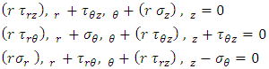 | (2.1) |
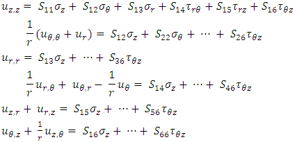 | (2.2) |
In the above,  are the displacement components in the radial, circumferential and longitudinal directions, respectively,
  are the normal stress components in the same directions and
  are the shear stresses on the
  face and
  face, respectively (Fig. 1). A comma indicates partial differentiation with respect to the indicated coordinates. The Sij’s (i , j = 1, 2,…, 6) in (2.2) are the components of compliance matrix and represent the directional properties of the material. The compliance matrix is symmetric, Sij = Sji.Complete anisotropy of the material is allowed for, making 21 independent material constants. We are not allowed to illiminate any of those components since the material properties depend on the manufactures set up, or, in the case of aerospace vehicles, a different gravity environment. The components can be expressed in terms of engineering constants as follows:
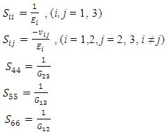 | (2.3) |
In (2.3), the Ei’s are the Young’s moduli in tension along the  direction and
  and
and  are the Poisson’s ratio and shear moduli in the i-j face, respectively. Equation (2.2) implies anisotropic property of the material only. Materials to be non-homogeneous, different properties of each layer of the shell, we will allow the material property variation in the radial direction as follows:
 | (2.4) |
Unlike the majority of theories, which identify material properties from the beginning, this theory willallow the properties to be, variable, as hybrid theory.The principal material axes (r', θ', z') in general do not coincide with the body axes of the cylindrical shell (r, θ, z). If the material properties S'ij with respect to material axes specified, then the properties with respect to the body axes are given by the anisotropic transformation equations:The shell is free from surface traction at its inner surface while the outer surface is subjected to a uniformly distributed tensile force. The boundary condition is then: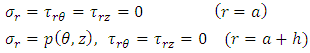 | (2.5) |
We will find it convenient to work with stress resultants rather than the stresses themselves. These stress resultants, which are forces and moments per unit length, are obtained by integrating with respect to the thickness coordinate. They are: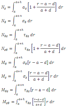 | (2.5) |
In the above, a is the inner radius of the cylindrical shell and d is the distance from the inner surface to the reference surface where the stress resultants are defined. Note that NƟz and NzƟ and MzƟ and MƟz respectively are different. This is due to the fact that the terms of the order of thickness over radius are not neglected compared to one in the integral expressions.
3. Formulation of a Boundary Layer Theory
As explained in the introduction, a theory of shells is distinguished from the exact three dimensional elasticity formulation by the fact that one of the coordinates is suppressed by the mathematical description. The procedure used here for obtaining the two dimensional thin shell equations is that of the asymptotic integration of the (2.1) and (2.2) describing the cylindrical shell. As a first step for integrating (2.1) and (2.2), we non-dimensionalize the coordinates as follows: | (3.1) |
where L and  are quantities which are to be determined later.Next, the compliance matrix, the stresses and deformations are non-dimensionalized by the use of a representative stress level σ, a representative material property S and the shell radius a as follows:
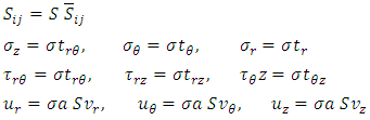 | (3.2) |
Where the dimensionless displacements and stresses are functions of  These variables, together with their derivatives with respect to
  are assumed to be of order unity. The parameters
  introduced in (3.1) are thus seen to be characteristic length scales for changes of the stresses and displacements in the axial and circumferential directions, respectively.Consider a small parameter €, € < 1. With respect to an arbitrary domain D of the cylinder, M1 is said to be of order €n relative to a second quantity M2.
 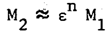 | (3.3) |
Where n is an arbitrary between 0 and infinity If everywhere in D (with the possible exception of some isolated small regions) the relation 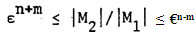 | (3.4) |
holds for a suitably chosen value of m, 0 < m < 1. According to this definition, two quantities are of the same order if n = 0 in the above, while a quantity is of order unity when n = 0 and M1 = 1. Substitution of the dimensionless variables defined by (3.1) and (3.2) into the elasticity equations, (2.1) and (2.2), yields the following dimensionless equations: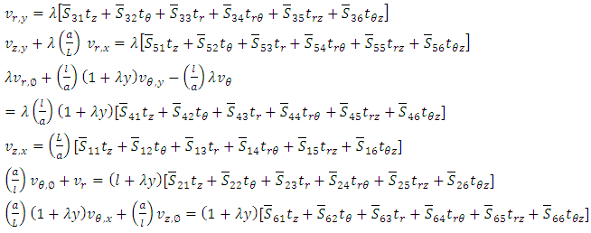 | (3.5) |
 | (3.6) |
Where λ is the thin shell parameter, defined as  | (3.7) |
The parameter λ is representative of the thinness of the cylindrical shell. We will consider only the case of thin shell theory as | (3.8) |
The dimensionless coefficients Sij of the compliance matrix in general are not all of same order. We therefore assume that they can be expanded in terms of finite sum as: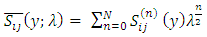 | (3.9) |
Where Sij(n) (y) is of order unity or vanish identically. Next, we assume that each displacement components, represented by the generic symbol v and each stress component, represented by the generic symbol v, and each stress components represented by the generic symbol t, can be expanded in terms of a power series in λ1/2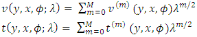 | (3.10) |
The v(m) and t(m) are of order unity. No convergence properties are assumed for series (3.10) except only asymptotic validity for λ. That is, if expansions (3.10) are terminated at some power of λ1/2, the error in using the expansions rather than the exact solutions tends to zero as λ approaches zero.Length scales  are as yet arbitrary. Their choice, as will be seen in the subjects to follow, determines the type of shell theory to be identified. Based in part on the results obtained for isotropic, homogeneous shells as shown in Reference [6], the developed theory is equivalent Donnell-Vlasof thin cylindrical shell equation.The last step of the procedure consists of substituting the expansions for the series and assumed length scales into the dimensionless elasticity equations of stress-displacement and equilibrium described by (3.5) and (3.6). Upon selecting terms of like powers in λ1/2 on both sides of each equations and requiring that the resulting equations be integrable with respect to the thickness coordinate as well as be capable of identifying the relations for all stresses and displacement components, we will obtain systems of differential equations. The first system of equations of “thin shell” theory and we will call it the first approximation system. We can, however, obtain stresses and displacements of each layer of thickness coordinate, which can be an advantage of the procedure among others. In the following section, the thin shell theories for the combinations of length scales can be derived.
4. Shell Theory of Longitudinal and Circumferential Length Scales (ah)1/2
We will now develop a theory of both characteristic length scales same as (ah)1/2, as follows | (4.1) |
In the above a is inner radius of cylindrical shell and h is the total thickness of the wall as shown in Figure 1 and Figure 3.The basis of the above equations are first non-dimensionalize each and all the variables to compare the magnitudes on equal basis and empirical number, which is used in the theory of shells.The following systems of differential equations are obtained by substituting the characteristic length scales (4.1) into (3.5) and (3.6).By substituting the asymptotic expansions (3.10) for the displacements and stresses and expansions (3.9) for the compliance matrix, we obtain the following systems of equations representing the first approximation theory. | (4.2) |
From the initial terms chosen for the first approximation system. where vr , vƟ, vz are the components of displacement at y = 0 surface. You will find the linear y dependence of the in-plane displacements. We will then obtain the in-plane stress-strain relations: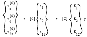 | (4.3) |
where strain components €i and curvature components ki defined at y = 0, surface are given as follows: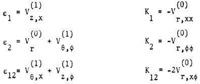 | (4.4) |
and [C] is the inverse of the first approximation compliance matrix.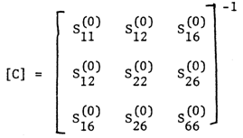 | (4.5) |
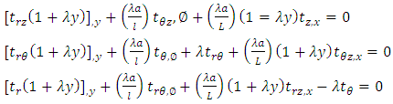
The transverse stresses can now be solved by substituting the in-plane stresses obtained in (4.4) into the last equations of (4.6) and integrating with respect to y, we then get: 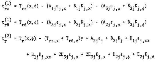 | (4.6) |
where Trz, TrƟ and Tr are the stress components at y = 0 and Aij , Bij , Dij and Eij are the products obtained by integration of stress strain coefficient components over the thickness coordinate. The boundary conditions are: 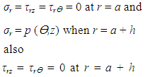 | (4.7) |
Where p* = p / (σλ), to non-dimensionalize.
5. Application
We assume here that the contact between layers is such that the strains are a continuous function in thickness coordinate. As the Cij are piecewise continuous functions, the in-plane stresses are also continuous. We would expect the in-plane stresses to be discontinuous at the juncture of layers of dissimilar materials. The transverse stresses are continuous functions of the thickness coordinate. We assume here that the contact between layers is such that the strains are a continuous function in thickness coordinate. As the Cij are piecewise continuous functions, the in-plane stresses are also continuous. We would expect the in-plane stresses to be discontinuous at the juncture of layers of dissimilar materials. The transverse stresses are continuous functions of the thick- ness coordinate.Although, as mentioned above, the theory developed can consider. Random layering, numerical results are to be carried out for a four-layer symmetric angle ply configuration. For this configuration the angle of elastic axes ɣ is oriented at + ɣ , - ɣ, - ɣ, + ɣ with the shell axis and the layers are of equal thickness.Let the cylinder be subjected to an internal pressure p, an axial force per unit circumferential length N and a torque T. The axial force is taken to be applied at r = a + H such that a moment N (H - d) is produced about the reference surface r = a + d. We introduce dimensionless external force and moments as follows: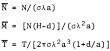 | (5.1) |
The cylinder is taken to be clamped at both ends but free to rotate and extend axially at one end. In theories developed in the previous chapters, the distance d, at which the stress resultants were defined, was left arbitrary. We now choose it to be such that there exists no coupling between Nz and Kz and Mz and €id. As the loading applied at the end of the shell is axisymmetric, all the stresses and strains are also taken to be axisymmetric. We thus can set all the derivatives in the expressions for the stresses and strains and in the equations for the displacements equal to zero.Numerical calculations are now carried out for a shell of the following dimensions:
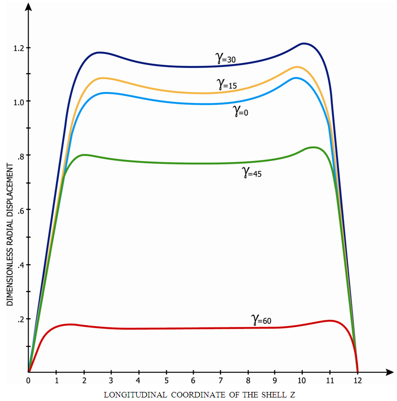 | Figure 4. Radial displacement of theory (ah)1/2 with different material angle of orientation 4 layer |
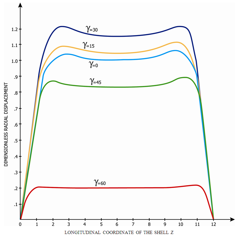 | Figure 5. Radial displacement of theory (ah)1/2 with different material angle of orientation single layer |
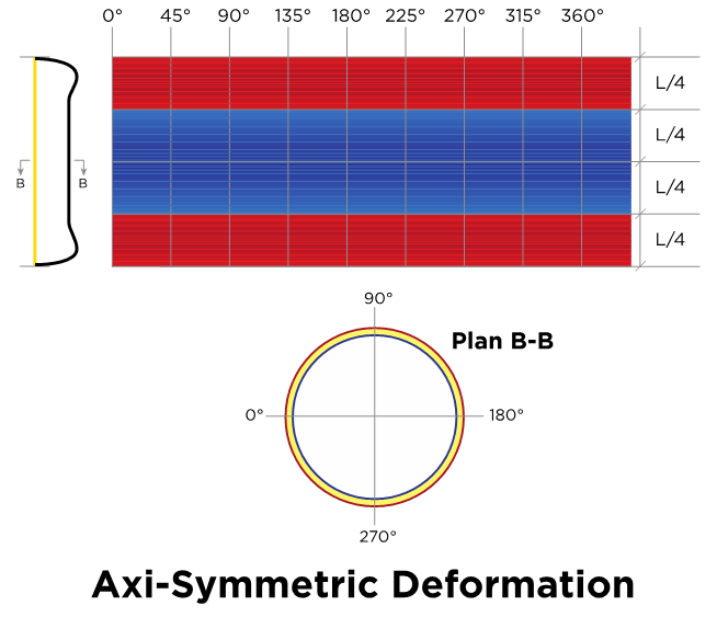 | Figure 6. Axi- symmetric deformation pattern |
We will then obtain λ= 0.025 (0.1 / 4.0). Each of the layers is taken to be 0.025 inches thick and thus the dimensionless distances from the bottom of the first layer are given by Each layer of the symmetric angle ply configuration (elastic symmetry axes y are oriented at (+ɣ, -ɣ, - ɣ, +ɣ) is taken to be orthotropic with engineering elastic coefficients of Apollo 38-750 Graphite Fiber as follows:
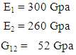 Here, direction 1 signifies the direction parallel to the fibers, while 2 is the transverse direction. Angles chosen were ɣ = 0, 15, 30, 45 and 60. Use of the transformation equations (2.6) then yields the mechanical properties for the different symmetric angle ply configurations.Shown in Fig. 3 is the variation of the dimensionless radial displacement with the actual distance along the axis for the different ply angles. The reference surface for the chosen configuration is given by d/h = ½. The integration constants are determined from the edge conditions. The radial deformations of the length scales (ah)1/2 is shown in Fig. 3. One will notice the radial deformation rapidly increases along the length scale near the edge while further inside deformations show little change. This area is the so-called edge effect zone or boundary layer; the American Petroleum institute adopted similar theories for its cylindrical shell gas storage tank design (API 650). Locating the edge effect zone can simplifies the calculation of circumferential and longitudinal stiffeners as shown in the References [8] through [11], in relation to the buckling problems, Reference [15].It is also shown that wide variations in the magnitude of radial displacement take place with change in the cross-ply angle. The maximum displacement occurs at ɣ = 30 degrees while the minimum displacement is at ɣ = 60 degrees.In each case, the displacements increase in ɣ up to ɣ =30 degrees, and thereafter will decrease. Weak and smooth edge effects are the case for large cross-ply angles ɣ.
6. Conclusions
In this paper, we first discuss how the approximation shell theories are derived by use of the method of asymptotic integration of the exact three-dimensional elasticity equations for a hybrid anisotropic circular cylindrical shell.The analysis remains valid for materials, which are non-homogeneous to the extent that their properties are allowed to vary with the thickness coordinate.As a result of the application of this method, one can obtain shell approximate theory of various orders in a systematic manner. The first approximation theories derived in this paper represent the simplest possible shell theories for the corresponding length scales considered. Although 21 elastic coefficients are present in the original formulation of the problem, only six appear in the first approximation theories. The shell theories thus assume the existence of a plane of elastic symmetry. It was seen that various shell theories are obtained by using different combinations of the length scales introduced in the non-dimensionalization of the coordinates and that each theory possesses unique properties such as the orders of stress magnitudes, displacement components and edge effect penetration. In this research, we considered a theory with length scales of (ah)1/2 for both longitudinal and circumferential directions.To illustrate the use of these theories, the application to layered shells was shown. The specific problem considered consisted of a symmetric angle-ply configuration under load and edge conditions used in the laboratory to determine the mechanical properties of composites. The results of the analysis showed the radial displacement first increases with increase of the angle between the axis of elastic symmetry and longitudinal shell axis, being largest at 30 degrees. It then decreased with further increase in angle. The theory of axial and circumferential length scale of (ah)1/2 show as a significant edge effect exists and that the penetration of the edge effect changes with the angle in similar fashion as for the radial displacement, being deepest at 30 degrees. Finding the edge effect zone of a hybrid composite shells simplifies the task for locating the circumferential and longitudinal stiffeners. In this research, the theory is limited only for the case of longitudinal and circumferential characteristic length scales of (ah)1/2, it will be necessary to investigate the case of different shell theories with length scales for different loadings and different materials.
ACKNOWLEGEMENTS
The research was partially sponsored by Summit Partners in Menlo Park, California, USA.
References
| [1] | Love, A. E. H., A treatise on the mathematical theory of elasticity, 4th edition. New York, NY, USA: Dover Publications, 2011. |
| [2] | Donnel, L. H., Beams, Plates and Shells (Engineering societies monographs).: McGraw-Hill Inc.: ISBN-13: 9780070175938. |
| [3] | Reissner, E., “The effect of transverse shear deformation on the bending of elastic plates,” J. Appl. Mech., vol 12, no A, pp. 69-77, 1945. |
| [4] | Johnson, M. W. and Widera, O. E., “An asymptotic dynamic theory for cylindrical shells,” Studies Appl. Math., vol 48, pp. 205, 1969. |
| [5] | Widera, O. E., “An asymptotic theory for the motion of elastic plates,” Acta mechanica, vol 9, no 54, 1970. |
| [6] | Vlasov, V. Z., “General theory of shells and its application in engineering”, NASA TT F-99, National Tech. Information Service. |
| [7] | De Renzo, D.J., “Advanced Composite Materials, Products and Manufactures”, Noyes Data Corporation, ISBN 0-8155-1155-8. |
| [8] | Heslehurst, R. B., “Design and analysis of structural joints with composite materials”, DES. |
| [9] | Hashin, Z. and Herakovich, C. T., “Mechanics of composite materials”, Pergamon Press. |
| [10] | Li, Changhu and Wu, Zhe, “Buckling of 120 Degree Stiffened Composite Shell”, J of Composite StructuresVolume 128, Page 199, 2015. |
| [11] | Teeter, A. and Kolakowski, Z., “Buckling of thin walled Composite Structures with Intermediate Stiffeners”, Journal of Composite Structures, Volume 69, Issue 4. |
| [12] | Ting, T. C. T., “Anisotropic Elasticity”, Oxford Engineering Science Series 45, Oxford University Press. |
| [13] | Leo, D. J., “Engineering Analysis of Smart Material Systems”, John Wiley and Sons, Inc. |
| [14] | Christensen, R. M., “Mechanics of Composite Materials”, Dover Publications 2005. |
| [15] | Nemeth, M. P., “Conditions for Symmetries in the Buckle Patterns of Laminated Composite Plates”, NASA Technical Reports Server(NTRS), 2012-217589. |
| [16] | Salim, H.A. and Davalos, J.F., “Torsion of Open and Closed Laminated Composite Sections”, J of Composite Materials, Volume 39, Number 6, Sage Publication. |

 Abstract
 Reference
 Full-Text PDF
 Full-text HTML