Ala Tabiei , Raguram Murugesan
The Department of Mechanical Engineering, University of Cincinnati, USA
Correspondence to: Ala Tabiei , The Department of Mechanical Engineering, University of Cincinnati, USA.
| Email: |  |
Copyright © 2015 Scientific & Academic Publishing. All Rights Reserved.
This work is licensed under the Creative Commons Attribution International License (CC BY).
http://creativecommons.org/licenses/by/4.0/

Abstract
The thermal structural forming process of woven fabric composites is presented in this paper. A computational micro-mechanical model of loosely woven fabric is presented and used to simulate the thermo-forming of woven fabric composites. The model, which is developed by the principal author and incorporated in LS-DYNA, accounts for the fiber reorientation, trellis mechanism of the yarn and viscoelasticity of the fibers. The behavior of the woven fabric is studied with the classical hemispherical draping and cantilever bending simulations which are validated against experiments. The thermal structural analysis of the carbon/epoxy woven fabric composites is carried out through the bias extension and thermo-forming simulations with *PART_COMPOSITE option to include the resin along with the fabric. This method of incorporating the resin within two integration points of the fabric proved satisfactory as the simulation results were in good agreement with the experiment. The proposed model and simulation techniques would be an efficient tool in evaluating factors related to the composite manufacturing process.
Keywords:
Carbon fiber thermoplastic composites, Computational micro-mechanical model, Hemispherical draping simulation, Cantilever bending, Thermal forming, *PART_COMPOSITE
Cite this paper: Ala Tabiei , Raguram Murugesan , Thermal Structural Forming Simulation of Carbon and Glass Fiber Reinforced Plastics Composites, International Journal of Composite Materials, Vol. 5 No. 6, 2015, pp. 182-194. doi: 10.5923/j.cmaterials.20150506.07.
1. Introduction
An increased interest in the textile composites is evident in recent years. Although textile composites have long been recognized for their applications in various load bearing structures, understanding of the elastic and strength behavior of textile composites is something which still needs improvement to a larger extent. Woven fabric composites represent a class of textile composites in which two or more yarn systems are interlaced at an angle. Woven fabric composites provide more balanced properties in the fabric plane and higher impact resistance than unidirectional composites. The interlacing of yarns provides higher out-of-plane strength which can take up the secondary loads due to load path eccentricities, local buckling etc. They are preferred for high profile material manufacturing due to their strength, durability and most importantly formability into complex shapes. These materials are widely used in aerospace, automobile and other industries which are in need of more efficient materials. Hence it is important to understand the material behavior of woven fabrics to have better standard products. In an attempt to model the flexible fabric behavior, Tabiei et al. [1] [2] have come up with computational micro-mechanical models for both viscoelastic loose woven fabrics and flexible dry woven fabrics which are incorporated in LS-DYNA as MAT234 and MAT235 respectively. The complex architecture of the loosely woven fabrics makes it difficult to model. The proposed micro-mechanical model accounts for the crimping of the yarns as well as for their trellising with reorientation of the yarns and their locking. The model is accomplished with friction of the rotating yarns and 1-D viscoelastic stress-strain relationship with strain rate dependent failure criteria. This micro-mechanical model is used in this paper to simulate various composite manufacturing processes and to provide more insight on how the material behaves during manufacturing.Forming is the primary manufacturing process of woven fabric composites where the end product’s performance depends entirely on the material behavior of the fabrics and resin which get affected during the forming process [8] [10] [11]. The forming process of woven fabric composites is normally conducted at very high temperatures, which would be beyond the melting point of the resin. Tensile mechanism and the in-plane shear stiffness places a significant role in the forming process [8]. Since the resin is almost melt at such high temperatures, its influence is very less on the tensile mechanism but it has more significance in the in-plane shear stiffness property. Hence, it is important to take in account the fabric and the resin properties to simulate the material behavior of woven fabric composites during forming process.In this paper, we tried to simulate the woven fabric behavior and the woven fabric composite behavior separately with the proposed material model in LS-DYNA. The classical hemispherical draping simulation is performed with the woven fabric which captures the fiber reorientation and the in-plane shear behavior in terms of shear angles. The bending behavior of the woven fabrics is studied with the cantilever bending test and its results were compared with the experiment. The composite material is challenging to model as it needs to account both the resin and the fabric unlike the other two simulations mentioned above which studies only the fabric behavior. In order to simulate the behavior of the composite, a methodology has been implemented in which we used the option *PART_COMPOSITE in LS-DYNA to define the resin and fabric as different through-thickness integration points. Then the performance of different variations of the integration points (five setups) with the thermal forming simulation were studied and this methodology proved satisfactory in simulating the composite behavior during forming process.
2. Computational Micro-mechanical Model
A computational micro-mechanical model developed by Tabiei et al. [1] for the loosely woven fabric with viscoelastic crimped fiber is used in this paper. The developed computational material model [1] is implemented in the nonlinear dynamic explicit finite element code LS-DYNA that is compatible with the shell element formulation. A description of the model is presented below.
2.1. Representative Volume Cell
The representative volume technique, vastly used in the micro-mechanical models, is utilized hereafter. The Representative Volume Cell, shortly known as RVC, of the loosely woven fabric material model is extracted from the deformed pattern of the material. The RVC consists of an undulated fill yarn crossed over an undulated warp yarn (Fig. 1). The parameters of the RVC are: the yarn span, s, the fabric thickness, t, the yarn width, w, and the yarn cross-sectional area, S. The complex geometry of the yarns is simplified and they are represented as a pin-joint mechanism of straight viscoelastic bars connected at the middle cross over point by a rigid link (Fig. 2). The mechanism allows the in-plane rotation of the yarns about the rigid link as a trellis mechanism and the straightening of the undulated yarns depending on their tension.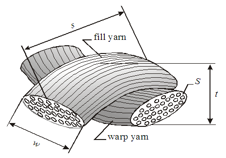 | Figure 1. Representative volume cell (RVC) of the model [1] |
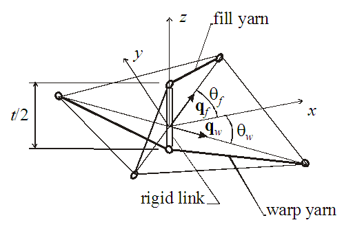 | Figure 2. Pin-joint bar mechanism [1] |
2.2. In-plane Yarn Rotation and Strain Transformation
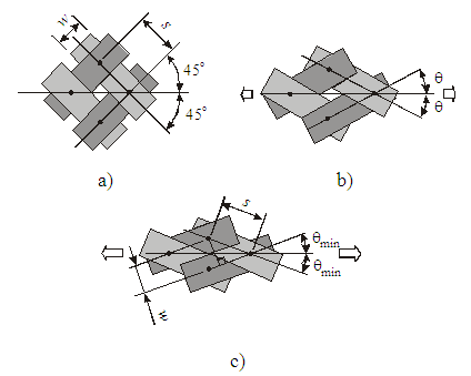 | Figure 3. Trellis mechanism of fabric: a) initial state; b) slightly stretched in bias direction; c) stretched to locking [1] |
The fabric material behaves in the plane of the fabric like a trellis mechanism when it is stretched in any non-yarn direction or sheared in the plane. The initially orthogonal yarns (Fig. 3a) are free to rotate (see Fig. 3b) up to some angle and after that the lateral contact between the yarns causes the locking of the trellis mechanism and the packing of the yarns (Fig. 3c). The minimum braid angle, θmin, can be calculated from the yarn width, w, and the span between the yarns, s: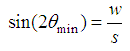 | (1) |
The other constrain angles as the locking range angle, θlock, and the maximum braid angle, θmax, are easy to be determined: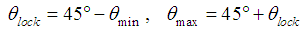 | (2) |
Initially, the braid angles of yarns, θf and θw are +45 and –45, respectively. The strain increment tensor of the RVC, ΔE, has to be transformed from RVC coordinate system to the yarn directions in order to determine the stress response of the yarns | (3) |
where Tf and Tw are the transformation matrices of the yarns as defined in reference [1].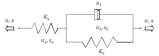 | Figure 4. Three element viscoelastic model [1] |
2.3. Viscoelastic Model
The viscoelasticity exists as a property of all materials but it is significant at room temperature for polymeric materials mainly. The material behavior can be simply described by a combination of one Maxwell element without the dashpot and one Kelvin-Voigt element.The simplified equation to determine the stress increment from the equilibrium equation [1] is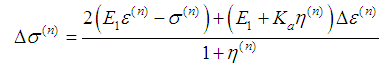 | (4) |
where  and
and  are as defined in reference [1].The strain rate dependent failure imposed on the model. We have two strain failure criteria: one for the Hookian spring providing the instantaneous elasticity
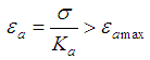 | (5) |
and the other for the Kelvin-Voigt element providing the delayed elasticity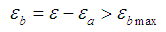 | (6) |
The input parameters for the viscoelasticity model of the material are only the static Young’s modulus E1, the Hookian spring coefficient Ka, the viscosity coefficient μb, the static ultimate strain εmax, and the Hookian spring ultimate strain εa max. The other parameters can be obtained as 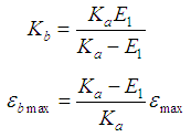 | (7) |
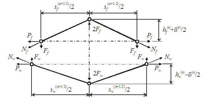
2.4. Equilibrium Position of the Central Nodes
 | Figure 5. Equilibrium position of central nodes |
We consider the equilibrium of the central nodes (the cross over point) of the yarns at time step n + ½ because the incremental viscoelasticity equations of the yarns are written for this instant. Again we assume that this state is linear interpolation of the states at time step n and time step n + 1. The equilibrium state is given in Fig. 5 for the fill yarn (upper scheme) and for the warp yarn (lower scheme). The span between the yarns and the length of the bars can be calculated for each time step of interest as follows: | (8) |
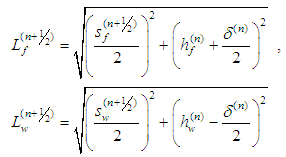 | (9) |
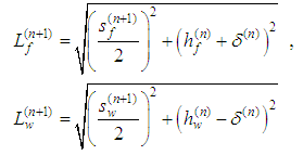 | (10) |
The vertical components of the yarn forces can be determined as follows: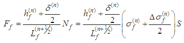 | (11) |
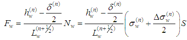 | (12) |
The equilibrium of the mechanism is reached when  | (13) |
Developing the Eq. (13) by substituting in the Eq. (9) and the Eq. (4) written for the fill and the warp yarns, we get the following simplified equation: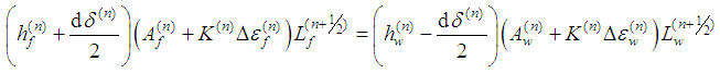 | (14) |
The strain increments of the yarns are determined by the expressions: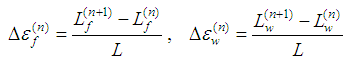 | (15) |
where L is the initial length of the bars [1].Substituting the yarn strain increments in Eq. (14) and plugging the Eq. (10) in, we can get the final equation after some small simplifications: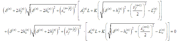 | (16) |
The Eq. (16) can be solved numerically for  by means of the Newton-Raphson method.The vertical position change of the central nodes is constrained in order to avoid the snap-through behavior of the mechanism,
 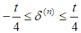 . In this way, the buckling of the yarns in compression is represented by the structural buckling of the membrane shell element model. The vertical positions of the central nodes, initially set to
 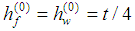 , are finally updated:
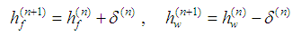 | (17) |
2.5. Stress Calculation
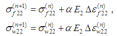
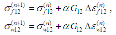
The strain in the yarns can be updated for the next time strep as,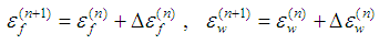 | (18) |
Similarly, the stress in the yarns is updated as,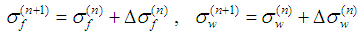 | (19) |
We can imagine that the RVC is smeared to the parallelepiped in order to transform the stress acting on the yarn cross-section to the stress acting on the element wall. The thickness of the membrane shell element used should be equal to the effective thickness, te, that can be found by dividing the areal density of the fabric by its mass density. The in-plane stress components acting on the RVC walls in the material direction of the yarns are calculated as follows: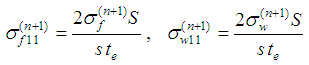 | (20) |
 | (21) |
 | (22) |
Then the final stress response of the model can be compiled from the yarn and the frictional stresses in RVC coordinate system as follows: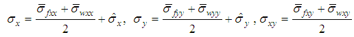 | (23) |
where  and
and  are as defined in reference [1].The membrane shell element formulation does not have resistance against the warping of quad finite elements and this could cause some instability in 3-D finite element models. This could be avoided by introducing transverse shear stiffness and calculating the transverse shear stresses in the shell element formulation.
3. Numerical Simulation
Numerical simulations using the proposed model have been performed in the explicit finite element package LS-DYNA. Comparisons are given between the present results and experimental data from literature to demonstrate the validity of the proposed model and the methodology used. The first two simulations consider only the fabric characterization and the following considers the composite characterization (fabric and the resin). The numerical simulations are presented below.
3.1. Fabric Characterization
3.1.1. Hemi-spherical Deep-drawing
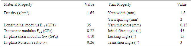
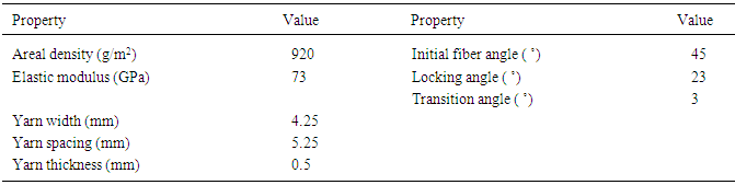
Deep-drawing is the most common composite manufacturing process in which the composite material is stamped into the desired final shape and geometry. Here we consider the classical and simplest deep-drawing process that is the hemi-spherical dome. The specimen is woven glass fiber fabric and is modelled with *MAT_VISCOELASTIC_LOOSE_FABRIC (*MAT_234). The fabric is square shaped and is 360mmx360mm in size. The edges of the fabric are free and is held in place by a blank holder over which a pressure equal to 2MPa is applied throughout the process. This prevents the fabric from moving and hence the formation of folds are efficiently prevented. The radius of the punch is 75mm and the dimensions of the other parts are given in the figure. The co-efficient of friction between the fabric and the tools are taken as 0.1. The material properties of the fabric and the dimensions of the yarn are listed in table 1. The yarn dimensions are taken from a micro-mechanical model [5] which is a general representation of plain weave fabrics due to the unavailability of data. The values of initial fiber angle, locking angle and the transition angle, given in Table 1, are assumed from some geometrical considerations.Table 1. Material properties [4] and yarn dimensions [5] of E-glass fiber fabric
 |
| |
|
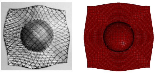
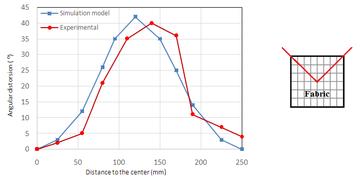
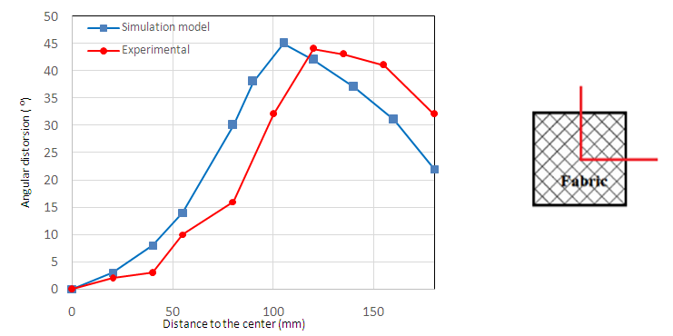
When the punch is lowered, the fabric is drawn down and it forms the shape of a hemispherical dome. During this process, the thickness of the fabric and the angle between the warp and weft changes. This change is more prominent in the dome part than the flat part of the fabric. The maximum shear is experienced by the fabric at the intersection of the dome and the flat part. It is where the maximum shear angle between the warp and weft are observed. The mechanical behavior of the fabric during the draping process depends on various factors like the material property, force on the holder, friction at the interfaces, punch speed, etc which are extensively studied in [6].The simulation is carried out for two initial fiber orientations of the specimen, 0˚/90˚ and -45˚/+45˚. The final shape of the draped fabric is compared with the experiment in Figs. 7, 8 and it is to be noted that the shapes of the draped fabric are different for different fiber orientation. Figs. 9, 10 shows the comparison of experiment and simulation results of the shear angles between the warp and weft for both fiber orientations (0˚/90˚ and -45˚/+45˚). The maximum angular distortion for the 0˚/90˚ fiber orientation is 42˚ and the distortion angles are measured along the diagonal axis starting from the center point of the fabric. Similarly, the maximum angular distortion for the -45˚/+45˚ fiber orientation is 45˚ and the distortion angles are measured along the median line starting from the center point of the fabric.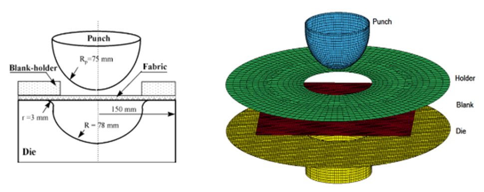 | Figure 6. The geometry [1] and the simulation model of the deep-drawing tools |
 | Figure 7. Comparison of draped shapes from experiment and simulation for 0˚/90˚ orientation |
 | Figure 8. Comparison of draped shapes from experiment and simulation for -45˚/+45˚ orientation |
 | Figure 9. Shear angle between the yarns on the diagonal line of 0˚/90˚ fabric |
 | Figure 10. Shear angle between the yarns on the median of -45˚/+45˚ fabric |
The shear angle values are obtained from the history variable 1 or 2 which are the material direction cosine and sine respectively. It is to be noted that the output from the material model is the angle of shear between the yarn (warp or weft) and the material axis. In order to get the shear angle between the yarns (warp and weft), which is reported in this paper, the values from the history variable 1 or 2 should be subtracted from the initial yarn angle (45˚) and is multiplied by 2.
3.2. Bending Analysis
Since woven fabrics are very flexible and sensitive to load variations, it is important to understand the bending behavior of the fabrics. Bending rigidity is a measure of a material’s ability to bend and it can be tested by the cantilever deflection test [7]. As in the literature, the specimen is made up of plain weave commingled glass/polypropylene woven preform and its properties are listed in Table 2. Table 2. Material properties and yarn dimensions of commingled glass/polypropylene woven preform [7]
 |
| |
|
The material properties of the polypropylene (PP) fibers in the commingled yarn were ignored because PP fibers are very flexible compared to the glass fiber, however, its weight is included in the fabric density [7]. The specimen is 100mmx30mm in size; it is fixed at one end and the other end is free. The specimen bends due to its self-weight and no other external loads are applied. The bending deflection of the fabric is in the warp direction and the weft direction was omitted assuming no difference between warp and weft direction. The comparison of the experimental and simulated deflected shape of the woven preform is presented in Fig. 11a. The simulation result is very much in agreement with the experiment. Also the deflected shape of the specimen along with its global axis is shown in Fig. 11b.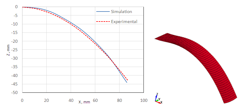 | Figure 11. (a) Comparison of deflected shapes of specimen from experiment and simulation. (b) Deflected shape from the simulation |
3.3. Composite Characterization
3.3.1. Bias Extension Test
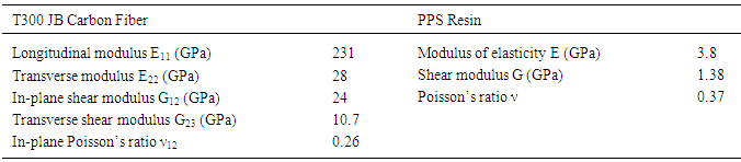
Bias extension tests are usually carried out in tension test machines. The experimental setup, test conditions and other information regarding the experiment are explained in literature [8]. Carbon fiber reinforced thermoplastic (CRFTP) composite laminates tested in this work are composed of carbon woven fabrics and Polyphenylene Sulfide (PPS) resin. PPS is a high temperature performance polymer with a melting point of 280˚C. The dimensions of the specimen are 210mmx70mm and the fabric is plain weave. It is fixed at one end and displacement is applied at the other end at a constant rate of 5mm/min. The simulation is carried out at two different temperatures (295˚C and 310˚C) which are over the melting point of the resin. The initial fiber orientation of the specimen is ±45˚. The material properties used are listed in Table 3. The yarn dimensions and assumed yarn angle values are given in Table 4.Table 3. Material properties of carbon fiber and resin [9]
 |
| |
|
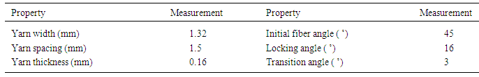
Table 4. Yarn angles and yarn dimensions of the carbon fiber fabrics [9]
 |
| |
|
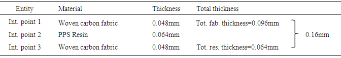
Since the material model contains only the fabric mechanization, we used the option *PART_COMPOSITE in LS-DYNA to account for the resin material. The specimen is modeled as a composite shell with three through-thickness integration points. Each integration point is assigned a material, thickness and material angle. The thickness of each integration point is arrived based on the fiber volume fraction of the material (0.6) such that the total fabric thickness is 60% of the total thickness and the total resin thickness is 40% subsequently. This is well explained in the Table 5.Table 5. Explanation of the integration points in the composite laminate
 |
| |
|
As mentioned earlier, the fabric was modelled with MAT_234 and the resin was modelled with MAT_ELASTIC_PLASTIC_THERMAL (*MAT_004) in which the elastic modulus varies with temperature. The variation of elastic modulus with respect to temperature of the PPS resin (fortron®) in shown in Fig. 12.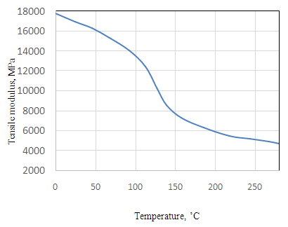 | Figure 12. Variation of Tensile modulus with temperature of the PPS resin (fortron®) |
With the above mentioned parameters and setup, the simulation is run and the results are compared with the experimental ones. Maximum effort is taken to replicate the experimental environment so as to get close enough to the experiment results. In Fig. 13, the before and after deformation of the specimen is shown and compared against the experimental ones. Fig. 14 is a plot of the tensile force against the shear angle between the warp and the wept which is compared with the experiment at two different temperatures. They are in good agreement with the experimental results.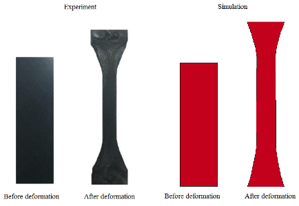 | Figure 13. Comparison of experimental [8] and simulation specimen before and after deformation |
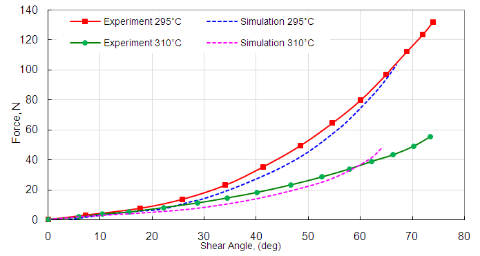 | Figure 14. Experimental [8] and simulation results of tensile force against shear angle for the bias extension test |
It is to be noted that the force at 295˚C is higher than the force at 310˚C. It is because the resin is almost melt at temperatures above 300˚C and the elastic modulus drops sharply after 295˚C and hence the composite becomes less stiff at temperatures beyond 300˚C. Also the maximum shear angle obtained was nearly 65 deg which is almost twice the locking angle (30 deg).
3.4. Hemispherical Thermo-forming
A thermal-structural analysis of the classical hemi-spherical draping is performed. The material of the specimen is the same as the one used in the bias extension test. The material properties and the yarn dimensions are given in the Table 4 and Table 3 respectively. The die and punch are modelled as rigid bodies. The radius of the punch is 75mm and it moves with a velocity of 3m/s. The size of the specimen is 300mmx300mm and its initial fiber orientation is 0/90. The specimen (blank) is held in place by a blank holder on which a compaction force of 300N is applied. The temperature of the specimen during the simulation is 300˚C.In addition to the integration point setup used in the bias extension simulation, four other variations of integration points were tried to study the effect of material variation within the integration points. The five integration point setups are shown in the Fig. 15 along with their values of thickness which was arrived based on the fiber volume fraction (0.6) of the material. The results are compared with the simulation result in the literature [8] which is shown in Fig. 16. 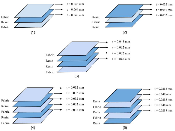 | Figure 15. Different sets of integration point variation along with their corresponding thickness values |
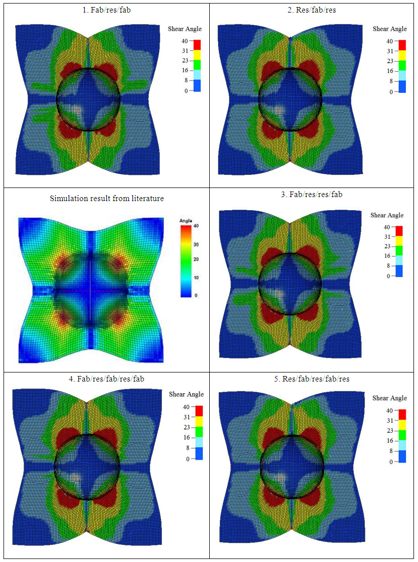 | Figure 16. Comparison of simulation results from literature [8] and five variations of the present model |
The shear angle fringe plots are quite similar to that of the one in the literature and the maximum shear angle is 40 deg. At such high temperatures, the resin is almost melt and hence the deformation of the laminate is predominantly controlled by the woven fabric. Due to the behavior of the resin, the forming tends to be easier and no wrinkles were formed. On comparing the shear angle fringe plots of the five variations of integration points, it is clear that two setups namely res/fab/res and res/fab/res/fab/res are better in terms of smooth plot of shear angle and are better representatives of the simulation result in the literature. It could also be inferred that the specimen behaves better when the outer integration points are defined with the resin material. The other three setups cannot be down-rated but the fact is that the former two are better performing among all five taken in consideration. A plot of the contact forces, between the punch and the fabric, for all the five integration point variations is shown in Fig. 17 which would help understand its effect on the formability of the composite.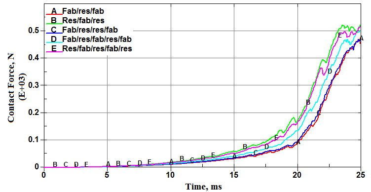 | Figure 17. Plot of contact forces (between punch and fabric) for all five variations of integration points |
4. Conclusions
The proposed micro-mechanical material model of loosely plain-woven fabrics can simulate almost thoroughly the behavior of the fabric material. It accounts for fiber reorientation, yarn rotation and viscoelasticity of the fibers. The fabric characterization has been demonstrated through the hemispherical draping and the cantilever bending simulations which were in good agreement with the experiment. Also the composite characterization, defining the resin and the fabric as different integration points using *PART_COMPOSITE option, proved satisfactory with thermal forming and bias extension simulations. In particular, the simulations are consistent with test results in predicting fiber reorientation and the temperature effect on the composite lamina. Various integration point setups are studied and a conclusion is made based on the performance of the specimen. Thus, the proposed model and the implemented simulation methodology are efficient tools for evaluating factors related to the composite manufacturing processes and of significant help to design pre-forming sequence for the manufacturing of fabric reinforced composites.
References
| [1] | Ala Tabiei, et al. Loosely woven fabric model with viscoelastic crimped fibers for ballistic impact simulations. International journal for numerical methods in engineering 61 (2004); 1565–1583. |
| [2] | Ala Tabiei, et al. Computational micro-mechanical model of flexible woven fabric for finite element impact simulation. International journal for numerical methods in engineering 53 (2002); 1259–1276. |
| [3] | Abdelhakim Cherouat, Jean Louis Billoet. Mechanical and numerical modelling of composite manufacturing processes deep-drawing and laying-up of thin pre-impregnated woven fabrics. Journal of Materials Processing Technology 118 (2001); 460–471. |
| [4] | L. Dong, C. Lekakou, M.G. Bader. Solid mechanics draping simulations of woven fabrics. Proceedings of ICCM-XII, 1999. |
| [5] | M. Nishia, T. Hirashima, T. Kurashiki. Textile composite reinforcement forming analysis considering out-of-plane bending stiffness and tension dependent in-plane shear behavior. 16th European conference on composite materials, June 2014. |
| [6] | L. Dong, C. Lekakou, M.G. Bader. Solid-mechanics finite element simulations of the draping of fabrics: a sensitivity analysis. Composites: Part A 31 (2000); 639–652. |
| [7] | Ryeol Yu, Michael Zampaloni, Farhang Pourboghrat, Kwansoo Chung, Tae Jin Kang. Analysis of flexible bending behavior of woven preform using non-orthogonal constitutive equation. Composites: Part A 36 (2005); 839–850. |
| [8] | Qianqian Chen, Philippe Boisse. Chung Hae Park, Abdelghani Saouab, Joël Bréard. Intra/inter-ply shear behaviors of continuous fiber reinforced thermoplastic composites in thermoforming processes. Composite Structures 93 (2011); 1692–1703. |
| [9] | S. Daggumati, W. Van Paepegem, J. Degrieck, J. Xu, S.V. Lomov, I. Verpoest. Local damage in a 5-harness satin weave composite under static tension: Part II – Meso-FE modelling. Composites Science and Technology 70 (2010); 1934–1941. |
| [10] | N. K. Naik, P. S. Shembekar. Elastic behavior of woven fabric composites: I – Lamina analysis. Journal of Composite Materials (1992); 2196-2225. |
| [11] | Masato Nishi, Tetsushi Kaburagi, Masashi Kurose, Tei Hirashima, Tetsusei Kurasiki. Forming simulation of thermoplastic pre-impregnated textile composite. International Journal of Chemical, Nuclear, Metallurgical and Materials Engineering Vol:8 No:8, 2014. |

 Abstract
 Reference
 Full-Text PDF
 Full-text HTML