-
Paper Information
- Previous Paper
- Paper Submission
-
Journal Information
- About This Journal
- Editorial Board
- Current Issue
- Archive
- Author Guidelines
- Contact Us
International Journal of Composite Materials
p-ISSN: 2166-479X e-ISSN: 2166-4919
2015; 5(6): 148-154
doi:10.5923/j.cmaterials.20150506.02

Investigation of Bond between Fibre Reinforced Polymer (FRP) Composites Rebar and Aramid Fibre-Reinforced Concrete
 Abstract
 Reference
 Full-Text PDF
 Full-text HTML
Savaş Erdem1, Tuğba Kağnıcı1, Marva Angela Blankson2
1Department of Civil Engineering, University of Istanbul, Avcilar Campus, Istanbul, Turkey
2Department of Civil Engineering, University of Technology, Jamaica, Kingston, Jamaica
Correspondence to: Marva Angela Blankson, Department of Civil Engineering, University of Technology, Jamaica, Kingston, Jamaica.
| Email: |  |
Copyright © 2015 Scientific & Academic Publishing. All Rights Reserved.
This work is licensed under the Creative Commons Attribution International License (CC BY).
http://creativecommons.org/licenses/by/4.0/

This paper reports on a study of the bond between Aramid fibre-reinforced concrete (AF) and glass fibre reinforced polymer (GFRP) rebars. Three types of GFRP rebars were used, namely, ribbed, helically deformed, and sand-coated bars. Traditional concrete was used as the reference cementitious material. Comparative analysis showed that the compressive strength of the Aramid fibre concrete was lower than that of the traditional concrete and this was attributed to the flocculation of the fibres in the concrete. Conversely, the impact strength of the AF was superior to that of reference concrete. A comparison of the bond strength in the GFRP-reinforced control and the GFRP-reinforced AF concrete samples showed that the introduction of the GFRP rebars in the latter produced mixed results. That is, the bond strength between the concrete and the ribbed bars was increased when Aramid fibres were used. However, the addition of Aramid fibres to the concrete did not increase the bond strength at the inteface of the helical rebar and, in the case of sand-coated GFRP rebar, the use of the Aramid fibres resulted in the reduction of bond between the concrete and this type of rebar.
Keywords: Aramid fibres, Concrete, Adhesion, Mechanical testing
Cite this paper: Savaş Erdem, Tuğba Kağnıcı, Marva Angela Blankson, Investigation of Bond between Fibre Reinforced Polymer (FRP) Composites Rebar and Aramid Fibre-Reinforced Concrete, International Journal of Composite Materials, Vol. 5 No. 6, 2015, pp. 148-154. doi: 10.5923/j.cmaterials.20150506.02.
Article Outline
1. Introduction
- Reinforced concrete is a composite material and it can perform its designated functions only if there exists adequate bond between the reinforcement and concrete [1-4]. Generally, steel reinforcing bar is used as reinforcement in concrete structures. However, corrosion of the reinforcing steel bars in concrete can lead to serious problems [5] such as structural and durability deficiencies in the structures. It has been found that fibre reinforced polymer (FRP) rebars have a great potential to counteract such problems [6]. FRP reinforcing bars have several advantages over conventional reinforcing steel, namely FRP has higher tensile strength and fatigue resistance, and lower creep deformation and unit weight. Besides, FRP is naturally corrosion-resistant and it does not contribute to electro-magnetism [7]. In spite of the advantages of FRP reinforcement over conventional steel reinforcement, a direct substitution between FRP and steel rebar is not possible due to various differences in the mechanical and physical properties of the two types of bars. The main challenges that prevent the wide-scale use of FRP rebars as reinforcing materials for concrete structures are:● When subjected to tensile force in the direction of fibres, FRP exhibits linear elastic behavior up to failure. Therefore, it does not have any yield point which means it exhibits no ductility [8]. ● The modulus of elasticity for some types of FRP, namely aramid fibre-reinforced polymer (AFRP) and glass fibre reinforced polymer (GFRP) is much lower than steel, hence deflection and crack widths may control the design of reinforced concrete structures [9].● The bond behaviour of FRP rebars with concrete is different from that of steel rebars due to the non-isotropic material properties and the different surface texture of the FRP rebars [10]. ● Higher cost of FRP compared to steel, lack of familiarity with the new technology and limited availability of literature contributed to the slow adaptation of FRP as concrete reinforcement [11].Despite these challenges, FRP reinforcing bars have been introduced as reinforcement in concrete structures subjected to aggressive environments such as chemical and wastewater treatment plants, sea walls, floating docks, and under water structures [12-14] not only because of their perceived capacity to endure in corrosive environments but also because of the other stated favorable attributes.Numerous studies have been carried out to investigate the bond development of FRP rebars in traditional concrete. Researchers [15, 16] have studied the bond strength that is attained between different types of FRP bars in normal concrete and observed that the strength is dependent on the embedded length of the bar. More specifically, it is stated that the bond strength of the FRP rebar is reduced as the length of embedment increased. It was also reported that the strength of the concrete has bearing on whether the bond failure takes place at the rebar/concrete interface or within the concrete [15]. Further, as would be expected, the geometrical features of the deformation on the FRP have influence on the bond stress developed in traditional concrete and it is reported [17] that a certain minimum depth of projection should be made available to ensure acceptable bond performance.In this study, the performance of FRP rebars in aramid fibre-reinforced was investigated. Fibre reinforced concrete (FRC) may be defined as a composite materials made with Portland cement, aggregate, and incorporating discrete discontinuous fibres. The role of the randomly-distributed discontinuous fibres is to bridge across cracks that develop in the concrete, and hence, help to provide same post-cracking ‘ductility’. The fibres tend to increase the strain at peak load, and provide a great deal of energy absorption in the post-peak portion of the load/deflection curve [18]. The focus of this study is on the bond strength of fibre-reinforced concrete mixtures made with different types of FRP rebars.
2. Materials
2.1. Aramid Fibre
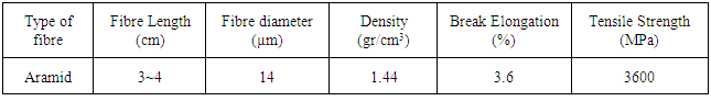
- Aramid fibres, with many favorable properties, are amongst the high performance modern fibres that are potentially of interest to civil and structural engineers [19]. The term aramid is used to refer to aromatic polyamides containing chains of aromatic (benzene) rings linked together with –CO- and –NH- end groups. Many forms can be produced, but those based on para links on the aromatic ring generally give the strongest fibres [20]. Some of the technical data on this type of fibre is provided in Table 1.
|
2.2. Fibre Reinforced Polymer Rebars
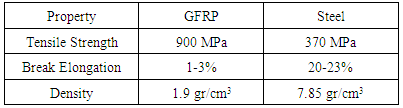
- As a composite material, the mechanical properties of FRP rebars vary significantly from one sample to another depending on the nature and volume of fibres, the mechanical properties of the resin and the fibre orientation. It is therefore not possible to establish universal values for the mechanical properties and only indicative values can be given. A comparison of FRP and steel rebars mechanical properties is shown in Table 2 [21].
|
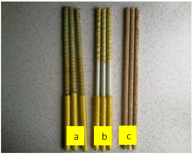 | Figure 1. Glass fibre reinforced polymer (GFRP) rebars a) helically deformed b) ribbed c) sand coated |
3. Methods
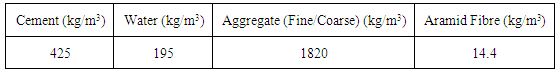
- All concrete mixtures were prepared using a mechanical mixer with a nominal capacity of 50 l. The process of mixing the concrete was done in the following order: the dry ingredients (cement, sand and coarse aggregates) were initially blended. Next, the water was gradually added and mixed together for 3 minutes. The fibres were then carefully sprinkled by hand in small amounts on the surface of the mixture followed by short period of mixing. This step was taken to avoid fibres balling and to achieve the highest uniformity in fibre distribution. The amount of Aramid fibre used was 0.5% based on volumetric measurement of the concrete. The mix proportions are provided in Table 3. For comparative analysis, a reference concrete mixture was produced in the same proportions shown in Table 3, with the exclusion of the fibres. After the mixing, the concrete with the fibre was used for the casting of the Aramid-type concrete samples and that without fibre for the control samples.
|
4. Results and Discussion
4.1. Compressive Strength Results
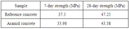
- After 7 and 28 days of curing, the 150 mm cubes were tested to determine the compressive strength (Figure 2) of each type of concrete. The testing machine which has a maximum capacity of 2000 kN, applied a loading of 0.50 kN /s (ASTM C39) to the samples. Compressive strength test results of the Reference (Ref) and Aramid fibre-reinforced (AF) concrete samples were are given in Table 4. As seen in Table 4, the compressive strength of Aramid-fibre reinforced concrete specimens at 7 and 28 days were 9.45% and 8.2% respectively less than the reference concrete at the same age. The reduction in strength that occurred after the fibres were incorporated in the concrete can be explained by the fact that, although clumping of fibres was minimized, it was not abated. This reduction in compressive strength is therefore attributed to the clumping of the fibres which resulted in the degradation of the uniformity of the concrete.
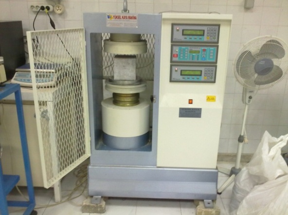 | Figure 2. Testing of compressive strength test specimen |
|
4.2. Charpy Impact Test Results
- Impact resistance (dynamic energy absorption as well as strength) is one of the important attributes of fibre reinforced concrete. The prismatic specimens having the dimensions of 40 × 40 × 160 mm were used to conduct the impact flexural test with Charpy equipment shown in Figure 3. The samples, before and after testing, are displayed in Figure 4.
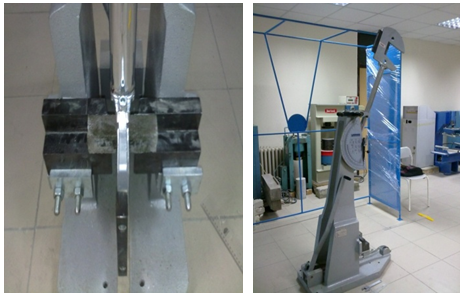 | Figure 3. Testing of Impact Charpy strength test specimen |
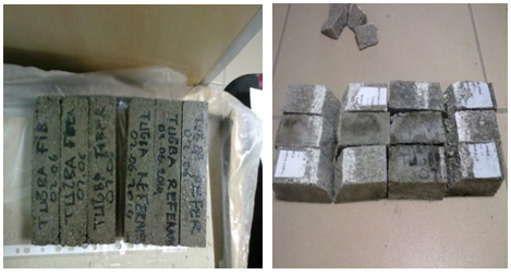 | Figure 4. Reference and Aramid fibre-reinforced samples before (a) and after (b) test |
 | (1) |
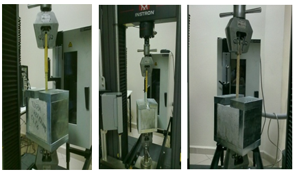
4.3. Pull-out Test Results
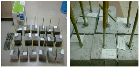
- The setup of the concrete samples for the bond strength is illustrated in Figure 5 and the actual test to determine the level of adhesion between the Aramid fibre-concrete and each GFRP bar was determined on machine shown in Figure 6. The reference (Ref) and Aramid fibre-reinforcement (AF) concrete samples before and after the test are shown in Figure 7 and the bond strength test results of the specimens are provided graphically in Figure 8. Calculation of bond strength was done using Equation 2.Calculation of bond stress,
 | (2) |
 = The average diameter of the test bar (mm) was used to include the effect of deformationl= Anchorage length (mm)A comparative analysis of the three sets of load/deflection graphs in Figure 8 shows that, the defection related to the peak load of each fibre-reinforced sample is larger than that obtained in the corresponding Ref sample. This larger deflection is the effect of the Aramid fibres which reduced the brittleness of the traditional concrete. An examination of Figure 8 showed the bond strength of the fibre-reinforced concrete got higher as the GFRP rebar in the concrete changed from sand-coated to helical to ribbed. The same observance is seen in the associate Ref samples. The characteristics of the surface texture and geometry make the difference. As the projection of the rebar got longer (as in the case of the ribbed bar), the effective embedded surface area increased and this elevated the level of adhesion and frictional force.
 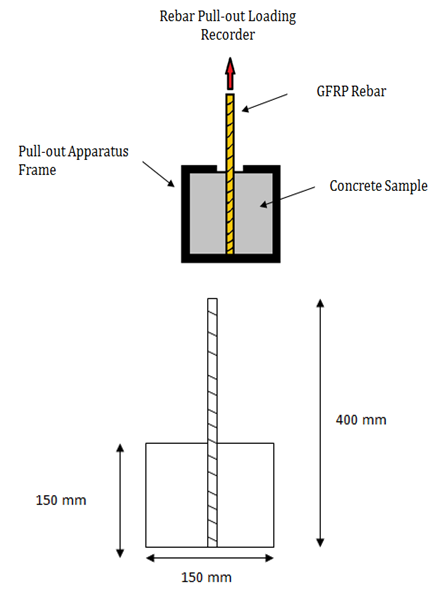 | Figure 5. Setup of sample for bond stress test |
 | Figure 6. Pull-out test specimen positioned on testing equipment |
 | Figure 7. Pull-out test specimens before and after experiment |
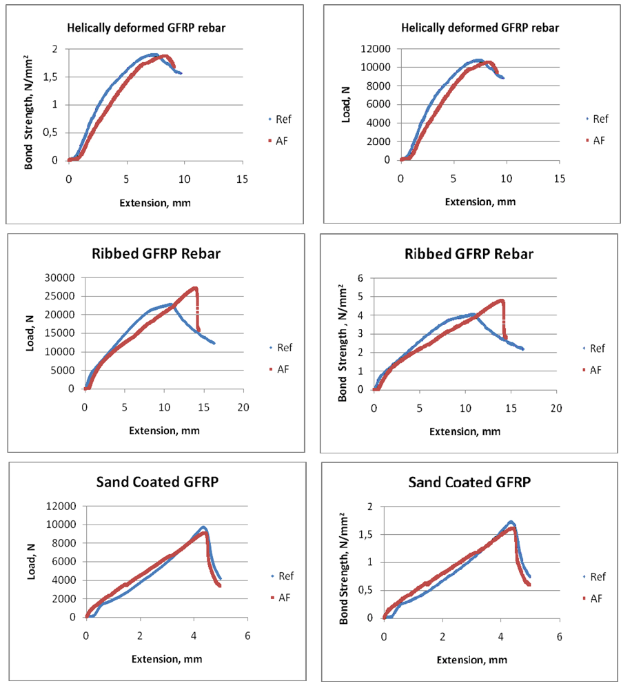 | Figure 8. Graphs of the load (N) - extension (mm) and bond strength (N/mm2)-extension (mm) data |
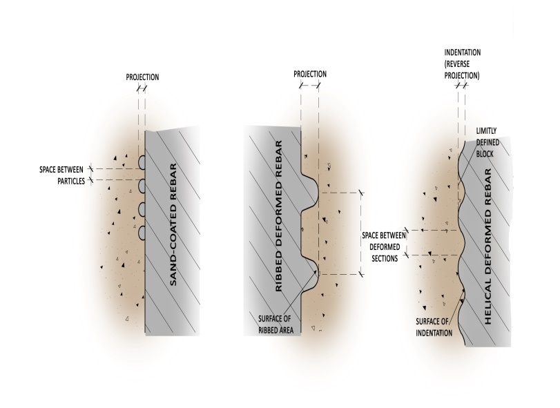 | Figure 9. Sketch showing the interface between Aramid fibre-reinforced concrete and a) sand-coated, b) ribbed and c) helically deformed rebars |
5. Conclusions
- From this study, the following represent the findings.● The compressive strength of concrete was reduced by the addition of Aramid fibres. The reduction in strength is attributed to the flocculation of the Aramid fibres. ● The impact resistance of fibre-reinforced concrete specimen was higher than that of control specimen. The micro-reinforced mortar reduced the development and rate of propagation of cracks.● The damage on the opposite side of the loaded surface of the fibre-reinforced concrete was more severe than that of the control concrete. This attribute is ascribed to the fibres in the concrete that enhanced the dynamic fracture toughness and increased the absorption of energy under impact loads.● The addition of Aramid fibres resulted in an increase in the bond strength of concrete when the ribbed GFRP rebar was used. The fibre in the mortar between the ribs of the rebar improved the tensile strength and increased the resistance to slippage at the interface at the concrete and rebar. The fibres also functioned as crack arrestors, by transferring stress across any occurring crack. This phenomenon consequently led to a stronger clasp of concrete on steel and an increase in bond strength.● However, the bond strength between the concrete and the respective helical-deformed and sand-coated rebars was not improved with the addition of the Aramid fibre.