-
Paper Information
- Paper Submission
-
Journal Information
- About This Journal
- Editorial Board
- Current Issue
- Archive
- Author Guidelines
- Contact Us
International Journal of Composite Materials
p-ISSN: 2166-479X e-ISSN: 2166-4919
2015; 5(5): 102-128
doi:10.5923/j.cmaterials.20150505.03
Design, Analysis, Fabrication and Testing of CFRP with CNF Composite Cylinder for Space Applications
S. Sankar Reddy1, C. Yuvraj2, K. Prahlada Rao3
1Department of Metro Production, M/s BEML Ltd., Bangalore, India
2Department of Mechanical Engineering, Madanapalli Institute of Technology & Science, Andhra Pradesh, India
3Department of Mechanical Engineering, JNTU College of Engineering, Andhra Pradesh, India
Correspondence to: S. Sankar Reddy, Department of Metro Production, M/s BEML Ltd., Bangalore, India.
| Email: |  |
Copyright © 2015 Scientific & Academic Publishing. All Rights Reserved.
Carbon Fiber Reinforced Polymers (CFRPs) have been widely used in numerous applications where high specific stiffness and strength offer structural weight reduction and fuel efficiency. RVS (re-entry vehicle system) structural protection to the weapon system during re-entry. These kinds of structures are realized using filament winding process. In this paper mechanical characterization of CFRP with Carbon Nano-fiber has been prented. Studies are carried out to characterize the strength and Young’s modulus of the composite structure. Carbon Nano-fibers are among the greatly potential reinforcing additives for polymeric composites due to their high axial Young’s modulus, high aspect ratio, large surface area, and excellent thermal and electrical properties. Various studies can be found in the literature regarding the incorporation of CNFs in polymeric matrices and the final mechanical and/or electrical properties of these materials. To prove the technology a composite cylinder having size Length of 600mm, Diameter 300mm and thickness 1.5mm is considered for experimental study. In the present work a method has been developed to analyze composite shell using Layered 46. In addition, 3D layered analysis of composite cylinder with end metallic plates have been performed to predict the Buckling behavior of the Composite shell. Composite shell were fabricated & tested with buckling load condition to verify the design and analysis procedure. It has been observed that the experimental results are in close agreement with the finite element analysis results, also the design stresses were within safe limits. Based on test results, the Longitudinal Strength of CFRP with CNF is achieved 1860 MPa, Young’s modulus is 118 GPa and improvement against CFRP with epoxy resin (LY556).
Keywords: CFRP, Carbon Nano-fibers (CNF), Buckling of Cylinder, Filament Winding, FE Analysis, Composite cylinder, Tensile strength, Young’s Modulus, Epoxy resin
Cite this paper: S. Sankar Reddy, C. Yuvraj, K. Prahlada Rao, Design, Analysis, Fabrication and Testing of CFRP with CNF Composite Cylinder for Space Applications, International Journal of Composite Materials, Vol. 5 No. 5, 2015, pp. 102-128. doi: 10.5923/j.cmaterials.20150505.03.
Article Outline
1. Introduction
1.1. Filament Wound Rocket Motor Case
- The filament winding technique offers high speed and precision for placing composite fibers. Continuous fibers can be oriented to match the direction and magnitude of stresses in a laminated structure, allowing optimal reinforcement loading. Since this fabrication technique provides the production of strong, lightweight, corrosion and chemical resistant parts, it has proved particularly useful for components of aerospace, hydrospace and military applications such as pressure vessels, pipe lines, rocket motor casings, helicopter blades, large storage tanks, etc. Typical pressure vessels consist of a cylindrical section and two quasi-spherical domes. Since the dome regions undergo the highest stress levels and are the most critical locations with regard to failure of the structures, the optimal design of the domes is one of the most important issues in the design of composite pressure vessels. Rocket motor casing is basically a pressure vessel with specially designed end fittings namely polar bosses and skirts. The end fittings are configured to suit to the fore end and aft end systems. Composite casings are popular as rocket motor casing as they provide high strength with low weight. Given a free hand, the rocket motor can be designed as a complete system and the casing can be designed to achieve the absolute maximum efficiency. However, when the designs of fore / aft end systems and that of casing are carried out in isolation keeping only the interfaces in mind, limited efficiency as depicted by weight saving, performance factor and cycle time, can still be achieved. The CFRP material is used for filament wound rocket motor case (CRMC). Generally realization of CRMC is observed with carbon fiber and epoxy resin by wet filament winding process. This composite having a longitudinal tensile strength of 1200MPa and modulus of 110GPa. Efforts are made for improving these properties by Formulating resin system.
1.2. Back Ground
- It has been proved that the optimal shape profile for a filament wound dome is a isotensoid [1, 6], on the basis of the netting theory [2]. The isotensoid, which provides the dome structure with the minimum weight and maximum carrying capacity, implies that all the rovings show uniform tensions throughout their length. It can be designed in such a way that the major stresses are carried only by the fibers of the laminate [3]. A number of studies have been conducted on the design of such structures. de Jong [4] presented the geometry and structural properties for isotensoid pressure vessels with the aid of the continuum theory, in which the behaviour of matrix in composites has been taken into account. The primary aim of this paper is to manufacture a composite cylinder with conductive polymer layer for Solid Rocket Motor Casing. Studies are carried out to characterize the conductive polymer properties and studied in different material like CFRP with Carbon Nanotube and Copper Nano-powder and their enhancement of properties.
2. Material Characterization
2.1. Introduction
- Composite material in the form of towpreg is the state of the art of technology. Towpreg find wide application in composite manufacture, especially, where components are manufactured by filament winding process. Handling point of view towpreg makes its easy and simple. Towpreg has consistent and uniform resin content and high friction factor to carry out non geodesic winding than wet winding material. Tensile strength and modulus of composite depends on fibre volume fraction of composite. Towpreg composite has high fibre volume fraction (6- 65%) than wet winding processed composite material. Percentage of Translation of carbon fibre strength in composite is higher in towpreg than that of filament wet winding process. Towpreg systems deliver more of fiber strand tensile strength, compared with wet wind systems, and the finished parts exhibit smaller variation in properties. The net result is that less material can be used for towpreg vessels of equal performance.The experimental characterization of carbon fibre T-700/epoxy towpreg composite material is necessary required for generation of mechanical properties data for analysis, design, and fabrication of structural components using that material and for quality control of the material.The testing of composite material offers unique surprises because of the special characteristics of composites, factrors not considered important in metals testing are very important in testing composites.In order to design composite products, a through experimental characterization of carbon fibre T-700/ Epoxy towpreg composite material and its behaviour is necessary.
2.2. Evaluation of Carbon Fibre T700/Epoxy Towpreg for Physical Parameters
- Indigenous developed Carbon fibre T700/Epoxy Towpreg was received from M/s Chemapol industries, Mumbai for characterization purpose. The specifications of the carbon fiber T700/Epoxy Towpreg are given below. The Towpreg must be evaluated for their respective properties before processing of laminates by filament winding process.
2.3. Experimental Characterization of Towpreg 700 / Epoxy Composite
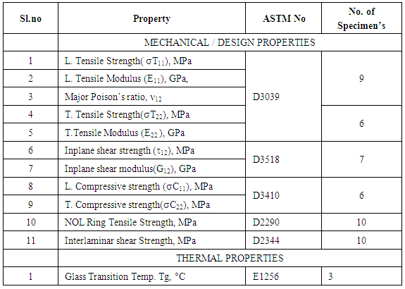
- Characterisation means determination of all effective Properties over sufficiently large volumes to represent composite and which are statistically reproducible.The main purpose of Experimental characterization data are• for checking micromechanical analysis• for design and analysis of practical structures• for Fabrication Process QA / Product QC• for Comparison of properties between candidate materialsWhen selecting a material for a specific product application like Composite Rocket Motor Casing for a missile system, the relevant properties of proposed composite material need to be determined experimentally designing a particular product to meet a specific structural requirement of the composite product.Experimental characterization of carbon fibre T700/ Epoxy towpreg composite was carried out for generation of design input data for design and analysis of composite rocket motor casings and other composite products. The mechanical and thermal tests for experimental characterization of carbon fibre T700/Epoxy towpreg composite are given in the following table 1.
|
2.4. Manufacturing Process of UD Laminates and NOL Rings
2.4.1. Fabrication of Unidirectional (UD) Laminates
- Flat UD laminates can be fabricated by filament winding in order to provide the stock from which flat test specimens can be prepared. One process for doing this involves winding a unidirectional mat over a large mandrel, cutting and removing the fibers, as wound material, from the mandrel, then plying, consolidating and curing (in an autoclave) to the flat configuration. The material resulting from the process can be quite different from the material in a filament wound composite structure. Towpreg was winding to a flat rectangular plate by filament winding by heating towpreg to temperature about 60°C by hot air gun at pay out eye and also heating at winding surface by IR lamps to temperature about 60°C to get good inter layer bonding during winding. 2 kg Tension was maintained per spool during winding. This flat shaped mandrel was specially designed and fabricated to prepare UD laminate as shown in the Fig. 1, 2.
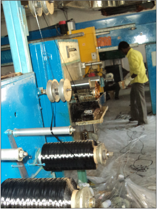 | Figure 1. Mounted Towpreg spools |
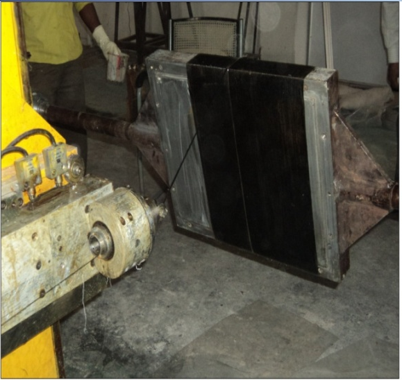 | Figure 2. Filament winding Process using Towpreg on flat Mandrel |
2.4.2. Curing
- After Filament winding, the laminate is cured in an oven having accurate temperature control. The flat mandrel is placed inside the oven on metal stands. The following cure cycle (as shown in Fig. 3) was followed • Raise temperature of the oven from room temperature to 120°C in 3minutes with heating rate of 2 to 4°C per minute• Hold the temperature at 120°C ±5°C for 2hours.• Raise temperature of the oven from 120°C to 150°C in 3 minutes with heating rate of 2 to 4°C per minute.• Hold the temperature at 150°C ±5°C for 4 hours• Switch off the oven and allow the component to cool naturally. • Open the door and remove mandrel when it is below 40°C
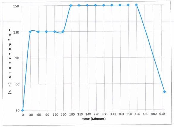 | Figure 3. Cure Cycle for Carbon Fibre T-700 / Epoxy Towpreg Composite |
2.4.3. Fabrication of NOL Ring Specimens
- NOL (Naval ordnance laboratory) Ring specimens that simulate the cylindrical geometry of composite over wrap pressure vessel (COPV). NOL ring specimens are prepared by Carbon fibre T700/Epoxy towpreg by filament winding technique on NOL ring mandrel as shown in the figure 4. NOL ring mandrel was specially designed and fabricated to prepare a laminate simulating the real filament wound. Hoop winding is carried out on the mandrel and followed above process parameter of towpreg mentioned in the preparation of UD laminates. Curing of NOL ring winding was carried out in oven with cure cycle. After curing, NOL Ring winding was machined on lathe to remove accumulated resin on winding during curing to get uniform thickness of ring sand winding was partitioned into standard width as ASTM 229 to get NOL Rings. The dimensions of NOL ring specimen is shown in the Fig.NOL winding and partition of winding into rings as shown in the Fig.
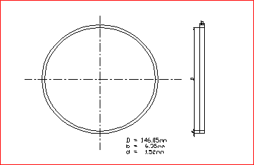 | Figure 4. NOL Ring Test Specimen (ASTM D 2290) |
2.4.4. Specimen’s Preparation from UD Laminates
- When selecting the type of test specimen to use in an experimental characterization, one of the most important point is to use a type of specimen which has been made in the same manner as the full scale end product structure. In the characterization programme described herein, the end product is carbon-epoxy filament wound rocket motor casing.It is desirable to characterize experimentally the properties of a single ply of the composite material for design purpose. However, practical considerations often prevent their construction. Thus, it becomes necessary to conduct tests on multi-layered specimens and use appropriate laminate theory to reduce the results in terms of single-ply properties.The dimensions of different types test specimens ((as shown in figure 5). Specimens are prepared from laminates with the help of a diamond wheel cutting machine (as shown in figure 6-10).
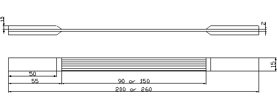 | Figure 5. Longitudinal Flat Tensile Test Specimen (ASTM D 3039) |
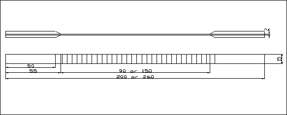 | Figure 6. Transverse Flat Tensile Test Specimen (ASTM D 3039) |
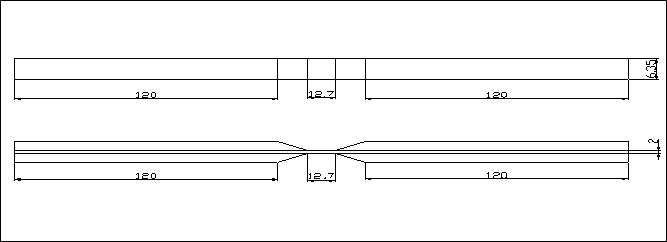 | Figure 7. Longitudinal Flat Compressive Test Specimen (ASTM D 3410) |
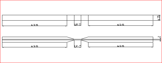 | Figure 8. Transverse Flat Compressive Test Specimen (ASTM D 3410) |
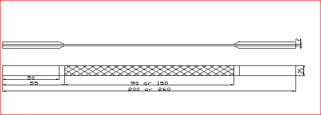 | Figure 9. In plane Shear Test Specimen (ASTM D 3518) |
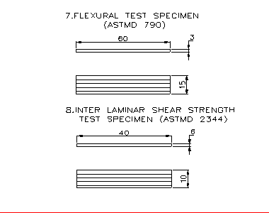 | Figure 10. Flexural specimens as per ASTM D 790 & ILSS Specimen as per ASTM D 2344 |
2.5. Test Methods for Laminates
2.5.1. Mechanical Properties
2.5.1.1. NOL Ring Tensile Test
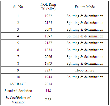
- This method covers the determination of the comparative apparent tensile strength of ring or tubular composites. An apparent tensile strength rather than a true tensile strength is obtained in this test because of a bending moment imposed during test. The method is applicable to many types of tubular shaped specimens either parallel-fiber reinforced, extruded or molded. Parallel fiber reinforced specimen is prepared and tested as per ASTM D229 using split disc test fixture for determining the apparent hoop tensile strength of the composite. NOL ring specimens were tested using NOL test fixture (as shown in Fig). A plot Apparent Hoop tensile strength vs. displacement of NOL Ring test is shown in Figure. Failure modes of NOL Rings is shown in Figure. The test results of NOL ring are shown in the Table 2.
|
 | Figure 11. NOL Ring preparation stages and Testing |
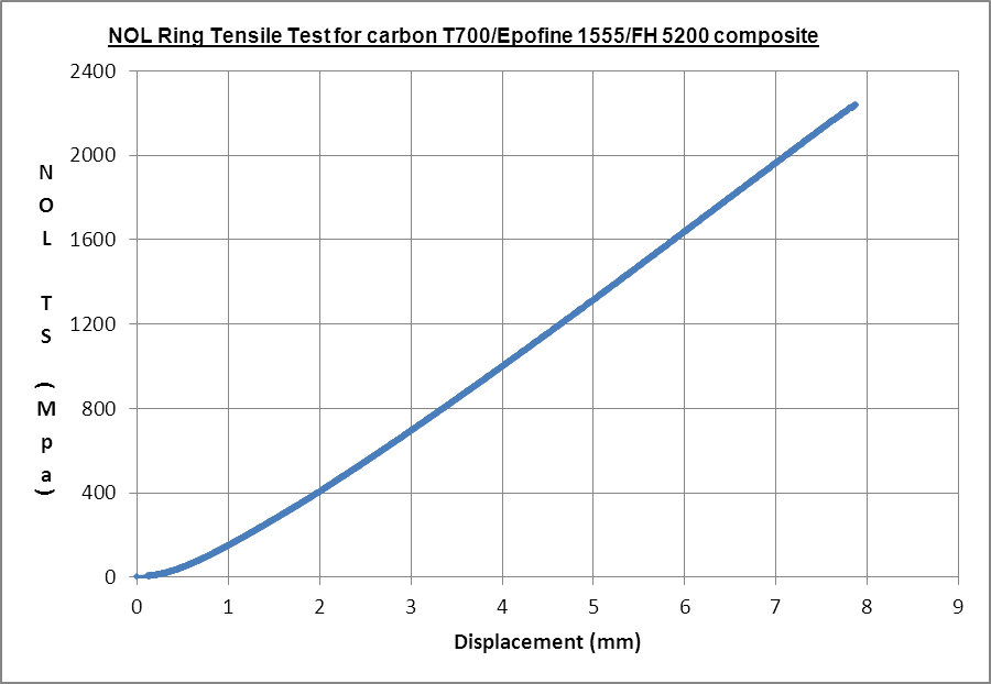 | Figure 12. Plot for Tensile Strength Vs Displacement |
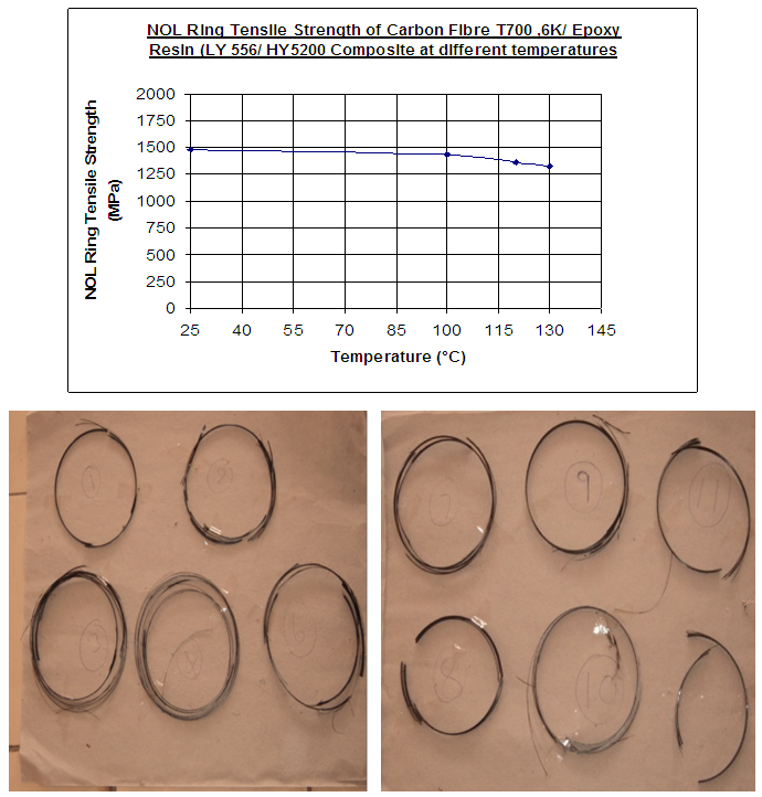 | Figure 13. NOL Rings were failed in delamination and circumferential splitting failure modes |
2.5.1.2. Tensile Test
- Tensile test on laminates will be performed in two directions namely• Tensile test in longitudinal direction• Tensile test in transverse directionLongitudinal Tensile TestThe tension test on longitudinal specimens is conducted to determine longitudinal tensile strength (XT), Modulus (EL) and major Poisson’s ratio (LT). In this method, the specimen with end tabs has been used. Rosette Strain gauge was bonded on specimens as per standard procedure of strain gauge bonding. Specimen preparation and testing is carried out as per the standard ASTM D3039.Rosette strain gauge was bonded on specimens for measurement of modulus and Poisson ration as shown in the fig. Longitudinal tensile strength is determined from the ultimate load and longitudinal tensile modulus is calculated from the stress-strain curve. The Tensile testing of UD laminate specimens in UTM with strain gauge data logger system is shown in the fig. Failure modes of specimens are shown in the fig. The plot of Tensile strength vs. strains is given in the Fig. for calculation of Ultimate tensile strength, tensile modulus, Poisson ratio. The values of the longitudinal strength, modulus, poisson ratio and ultimate failure strain are given in the Table.
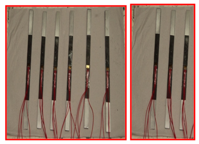 | Figure 14. UD Tensile Specimens |
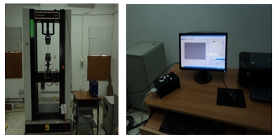 | Figure 15. UTM - 100KN Capacity with strain data acquisition system |
 | Figure 16. Tensile stress vs. strains of longitudinal UD tensile specimen |
|
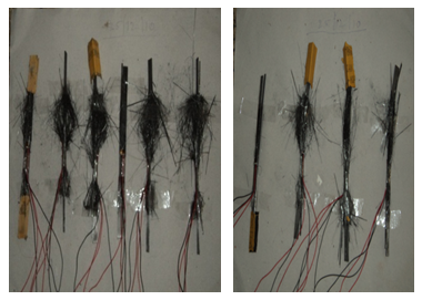 | Figure 17. Failure mode s of longitudinal Tensile Specimens |
|
2.5.1.3. Compressive Test Results
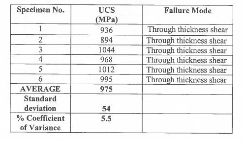
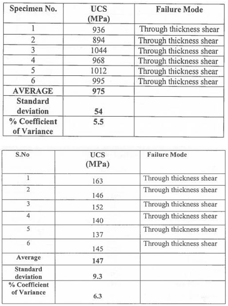
- Compressive test on laminates will be performed in two directions namely• Compressive test in longitudinal direction• Compressive test in transverse directionLongitudinal (0) compressive Test and Transverse (90) compressive tests are carried out to determine longitudinal and transverse compressive strength. Specimen preparation and testing is done as per the test standard ASTM D341by using IITRI fixture as shown in the Fig. Gauge length12mm was used for compressive testing of composites.
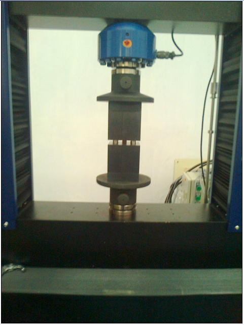 | Figure 18. IITRI test fixture for compression |
|
2.5.1.4. In plane Shear Test
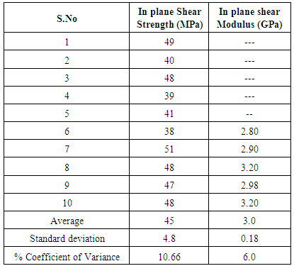
- The properties that are determined through the tests are the shear strengths and shear modulus. In these tests the specimen is subjected to loads that produce a pure shear state of stress and the resulting strains are measured.The test in which shear distortion takes place entirely in the plane of the composite material laminate are termed in-plane shear tests. The in plane shear strength (() and in plane shear modulus (G) are determined by this test. In this characterization programme of carbon-epoxy composites, the in-plane shear properties are determined by the uniaxial tension test on 45 specimens as per the test standard ASTM D3518.
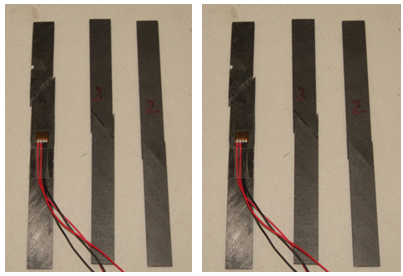 | Figure 19. Failure modes of specimens |
|
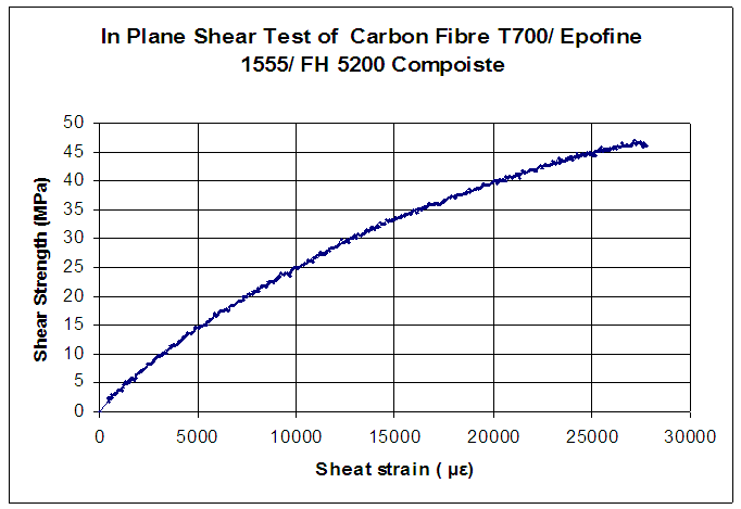 | Figure 20. Plot for Shear Strength vs. Shear Strain |
2.5.1.5. 3 Point Flexural Test
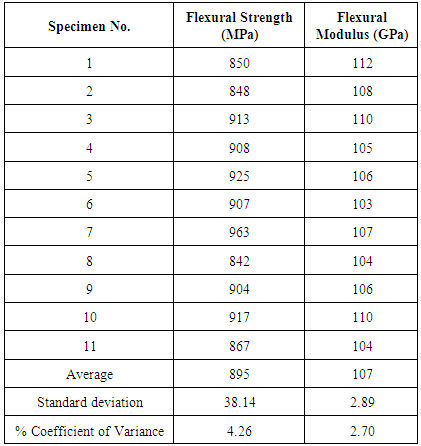
- The Flexural strength modulus are evaluated using a three-point test fixture. The specimen is prepared as per test method ASTM D790. Flat specimens, machined with same care and precision as previously described for tensile testing, are selected for measurements. The material direction under investigation must be oriented along the length dimension of the specimen. The test pieces require a span/depth (l/d) ratio high enough to achieve failure in bending rather than shear and minimize the influence of shear.l/d ratio 40:1 was used for testing.The Flexural strength (FS) is calculated as follows,FS = 3PL / 2bd2 where, p Maximum load L Support span length b width of specimen d thickness of specimen Flexural testing of UD specimens in UTM and failure modes are shown in the fig. A plot of Load vs. displacement of Flexural Test is shown in fig. The values of Flexural Strength and modulus are given in Table.
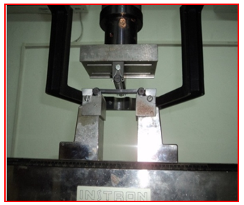 | Figure 21. 3 point flexural testing |
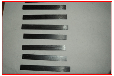 | Figure 22. Specimens after flexural testing |
|
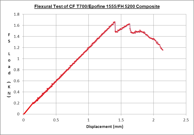 | Figure 23. Load Vs deflection curve for Flexural Test |
2.5.1.6. Inter Laminar Shear Strength (ILSS)
- The Inter laminar shear strength is evaluated using a three-point test fixture. The specimen is prepared as per test method ASTM D2344. Flat specimens, machined with same care and precision as previously described for tensile testing, are selected for measurements. The material direction under investigation must be oriented along the length dimension of the specimen. The test pieces require a span/depth (l/d) ratio low enough to minimize the influence of bending deformation and to achieve failure shear rather than bending. l/d ratio41 was used for testingThe Interlaminar shear strength (ILSS) is calculated as follows,ILSS = 3p/4bdwhere, p maximum loadb width of specimend thickness of specimenILSS Test of UD specimen in UTM and samples after tested are shown in fig. A plot of Load vs. displacement of ILSS Test is shown in fig. The values of Interlaminar Shear Strength (ILSS) are given in Table.
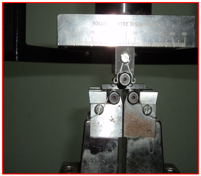 | Figure 24. ILSS Testing |
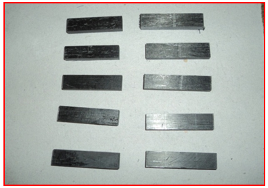 | Figure 25. Specimens after ILSS testing |
2.5.2. Thermal Properties
2.5.2.1. Glass Transition Temperature
- Glass transition temperature of unidirectional composite specimen was investigated as per ASTM E 1356 by recording DSC (DSC Q200) traces in Nitrogen atmosphere and flow rate5L/minute was used. A heating rate of 10(C/minute and a sample size of 11.8 mg was used. The value of Glass transition temperature found by DSC was 125-129(C.DSC scan of composite sample is shown in the Fig.
2.6. CNT Materials Characterization
2.6.1. Introduction
- Carbon nanotubes are nanostructure carbon materials having large aspect ratios, extremely high Young’s modulus and mechanical strength, as well as superior electrical and thermal conductivities. Incorporation of a small amount of carbon nanotubes into fiber’s, metals and ceramics leads to the formation of high performance and functional nano-composites with enhanced mechanical and physical properties.Considerable attention has been applied to the development and synthesis of carbon nanotubes-reinforced composites in the past decade. This is mainly focuses on the state of the synthesis, micro-structural characterization, physical and mechanical properties and application of carbon nanotubes-reinforced composites. The various synthetic and fabrication techniques, dispersion of carbon nanotubes in composite matrices, morphological and interfacial behaviours. Manufacturing of these nano-composites for commercial applications is still in an embryonic stage. Successful commercialization of such nano-composites for industrial and clinical applications requires a better understanding of the fundamental aspects. With a better understanding of the processing, structure and property relationship, carbon nanotubes-reinforced composites with predicted and physical/mechanical properties as well as good biocompatibility can be designed and fabricated.With tougher environmental regulations and increasing fuel costs, weight reduction in composites has become an important issue in the design of composite materials. The need for advanced composite materials having enhanced functional properties and performance characteristics is ever increasing in industrial sectors. Since their discovery by Ijima in 1991, carbon nanotubes (CNTs) with high aspect ratio, large surface area, low density as well as excellent mechanical, electrical and thermal properties have attracted scientific and technological interests globally. These properties have inspired interest in using CNTs as reinforcing materials for polymer, metal or ceramic-matrix composites to obtain light-weight structural materials with enhanced mechanical, electrical and thermal properties. Composite materials with at least one of their constituent phases being less than 100nm are commonly termed .nano-composites.. Remarkable improvements in the mechanical and physical properties of polymer-, metal- and ceramic nano-composites can be achieved by adding very low loading levels of nanotubes. So far, extensive studies have been conducted on the synthesis, structure and property of CNT-reinforced polymers. The effects of CNT additions on the structure and property have received increasing attention recently.
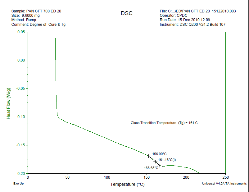 | Figure 26. DSC scan for Glass Transition Temperature |
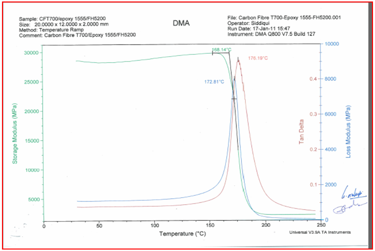 | Figure 27. DMA scan for Glass Transition Temperature |
2.6.2. Synthesis of Carbon Nanotubes by Electric Arc Discharge
- In the electric arc discharge technique is the simplest and less expensive method for fabricating CNTs. In the process, an electric (D.C.) arc is formed between two high purity graphite electrodes under the application of a larger current in an inert atmosphere (helium or argon). The high temperature generated by the arc causes vaporization of carbon atoms from anode into plasma. The carbon vapour then condenses and deposits on the cathode to form a cylinder with a hard outer shell consisting of fused material and a softer fibrous core containing nanotubes and other carbon nanoparticles. The high reaction temperature promotes formation of CNTs with a higher degree of crystallinity. The growth mechanism of catalyst-free MWNTs is not exactly known. The nucleation stage may include the formation of O2 precursor and its subsequent incorporation into the primary graphene structure. On the basis of transmission electron microscopy (TEM) observations. Open end growth mechanism in which carbon atoms are added at the open ends of the tubes and the growing ends remains open during growth. The thickening of the tube occurs by the island growth of graphite basal planes on existing tube surfaces. Tube growth terminates when the conditions are unsuitable for the growth.
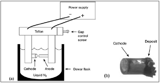 | Figure 28(a). Electric arc discharge |
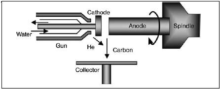 | Figure 28(b). Plasma rotating arc discharge |
2.6.3. Purification of Carbon Nanotubes
- CNTs prepared from arc discharge techniques contain various impurities such as amorphous carbon, fullerenes, graphite particles and metal catalysts. The presence of impurities can affect the performance of CNTs and their functional products significantly. Therefore, these impurities must be removed completely from nanotubes using appropriate methods. Typical techniques include gas-phase oxidation, liquid-phase oxidation and physical separation.Gas-phase and liquid-phase oxidative treatments are simple practices for removing carbonaceous by products and metal impurities from CNTs. In the former case, CNTs are oxidized in air, pure oxygen or chlorine atmosphere at 500°C. However, oxidative treatment suffers the risk of burning off more than 95% of the nanotubes materials. Another drawback of gas-phase oxidation is in homogeneity of the gas/solid mixture. The liquid-phase oxidative treatment can be carried out simply by dipping nanotubes into strong acids such as concentrated HCL,
 mixed 3: 1 ratio solution. In some cases, a two-step (e.g. gas-phase thermal oxidation followed by dipping in acids) or multi-step purification process is adopted, to further improve the purity of CNTs oxidation of nanotubes in sulfuric or nitric acid is quite slow and weak, but a mixture of the two yields better results. The best oxidant for CNTs is KMNO4 in acidic solution. In that oxidation by KMNO4 in an acidic suspension provides nanotubes free of amorphous carbon. The purification process also opens the nanotubes tips on a large scale, leading to the formation of carbonyl and carboxyl functional groups at these sites. The formation of such functional groups is detrimental to the physical properties of CNTs. However, it is beneficial for fully introducing CNTs into polymers. Carbon nanotubes are known to be chemically inert and react very little with polymers. Introducing carboxyl (COOH) groups into CNTs enhances the dispersion of CNTs in polymers because such functional groups improve the interfacial interaction between them. The efficiency of acid purification of CNTs can be enhanced dramatically by using microwave irradiation. In this technique, MWNTs are initially dispersed in a Teflon container containing 5M nitric acid solution. The container is then placed inside a commercial microwave oven operated at 210°C. During the purification process, nitric acid can absorb microwave energy rapidly, thereby dissolving metal particles from nanotubes effectively as shown in fig. 29(a) and fig (b).
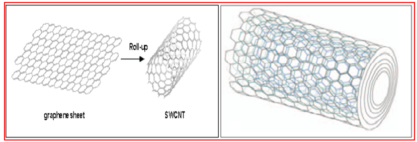 | Figure 29(a). SWCNTs and MWCNTs |
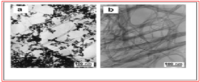 | Figure 29(b). Raw CNTs and purified |
2.6.4. Materials Characterization
- After purification, materials examination techniques must be used to characterize the quality and to monitor material purity of the nanotubes qualitatively or quantitatively. A rapid discrimination of the purity level of CNTs is essential for their effective application as functional materials in electronic devices and structural materials. Analytical characterization techniques used include SEM, TEM, energy dispersed spectroscopy (EDS), Raman, X-ray diffraction (XRD), optical absorption spectroscopy and thermo gravimetrical analysis (TGA). SEM and TEM can provide morphological features of purified nanotubes. The residual metal particles present in CNTs can be identified easily by EDS attached to the electron microscopes.
2.6.5. Selection of Composite Materials
- The material selection process requires the knowledge of the performance requirements of the structure or component under consideration. It also requires the knowledge of1. Types of loading, for example, axial, bending, torsion, or combination.2. Mode of loading, for example, static, fatigue, impact, shock, and so on3. Service life4. Operating or service environment, for example, temperature and humidity conditions, presence of chemicals, and so on5. Other structures or components with which the particular design under consideration is required to interact6. Manufacturing processes that can be used to produce the structure or the component7. Cost, which includes not only the material cost, but also the cost of transforming the selected material to the final product, that is, the manufacturing cost, assembly cost, and so on.
2.6.6. Selection of Carbon Fiber
- Fibers fall short of ideal performance due to several factors. The performance of a fiber composite is judged by its length, shape, and orientation, composition of the fibers and the mechanical properties of the matrix. The orientation of the fiber in the matrix is an indication of the strength of the composite and the strength is greatest along the longitudinal directional of fiber. This doesn’t mean the longitudinal fibers can take the same quantum of load irrespective of the direction in which it is applied. Optimum performance from longitudinal fibers can be obtained if the load is applied along its direction. The slightest shift in the angle of loading may drastically reduce the strength of the composite. Considering material T700 are carbon fibers made by Toray. Both of those fibers are a standard modulus carbon (around 230 GPa) but the T700 has a higher tensile strength (to 5000 MPa) as shown in fig. 30.
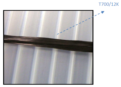 | Figure 30. Carbon fiber (12000 filaments) |
2.6.7. Selection of Epoxy Resin
- Epoxy resins (LY556) were first commercialized in 1946 and are widely used in industry as protective coatings and for structural applications, such as laminates and composites, tooling, molding, casting, bonding and adhesives, and others. The ability of the epoxy ring to react with a variety of substrates gives the epoxy resins versatility. Treatment with curing agents gives insoluble and intractable thermoset polymers. Some of the characteristics of epoxy resins are high chemical and corrosion resistance, good mechanical and thermal properties, outstanding adhesion to various substrates, low shrinkage upon cure, good electrical insulating properties, and the ability to be processed under a variety of conditions. Depending on the specific needs for certain physical and mechanical properties, combinations of choices of epoxy resin and curing agents can usually be formulated to meet the market demands. However, in terms of structural applications, epoxy resins are usually brittle and notch sensitive. As a result, tremendous effort has been focused on toughness improvement during past three decades.Make an excellent matrix material because of their Versatility, • Good handling characteristics, • Low shrinkage, • Excellent adhesive properties, • Flame resistant, • Good chemical resistance, • Good mechanical properties including toughness, • Offer considerable variety for formulating Prepregs resins, • Hot molding (cold molding rarely), • High smoke emission, • Curing temperature is 120-175°C (250-3500F), and • No by-products formed during cure. Hardeners (HY5200): hardeners are added to resin to lower the mixture viscosity. This resin and hardener are heated & mixed at certain temperature at 45°C.Mixing ratio of resin & hardener: per 1kg of epoxy resin, 270gm of hardener is added and 0.5 Gms of CNTs are added by using ball milling process these CNTs are uniformly distributed in the resin as shown in fig. 31.
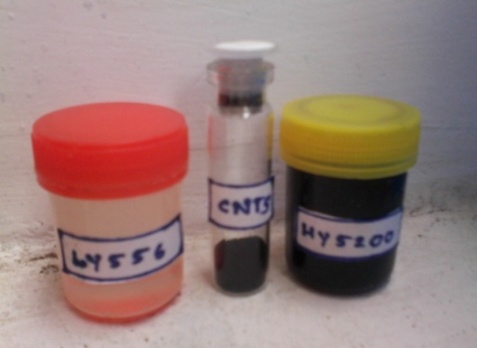 | Figure 31. Epoxy resin, CNTs and Hardener |
2.6.8. Result & Discussion
- I. TGA (Thermo gravimetric Analyzer):At initial stage raw and purified MWNTs taken has taken as 100 wt% we observed that there is no moisture entrapment in CNTs and also weight loss started at 500°C raw MWCNTS .within the100°C (500°C - 600°C) we observed 60% weight loss g 40% of raw MWCNTs standard up to 820°C as shown in fig. 32(a).
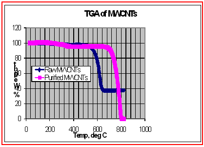 | Figure 32(a). TGA (Thermo gravimetric Analyzer) |
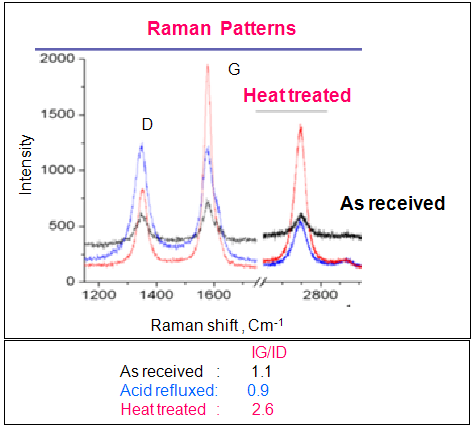 | Figure 32(b). Raman spectroscopy results |
2.7. Composite Material Data
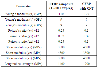
- The shell body fiber and resin system comes from a trade off driven by performance, cost and previous experience. The stiffened shell is an axisymmetric thin shell that, during normal operating condition, is predominantly under tensile stress. These stresses vary along the axis of the shell while subjected to compressive load. Filament winding is an obvious choice to realize the casing as it provides an efficient netting system of fibers, in which the benefit of variability of directional strength is utilized. The mechanical properties used in the casing design as well as analyses are given in Table 8 & 9.
|
|
3. Design of Composite Cylinder
3.1. Introduction
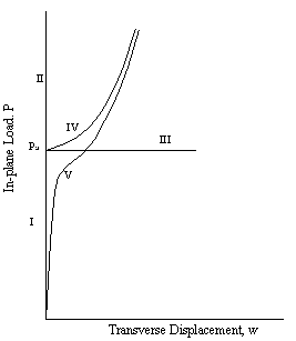
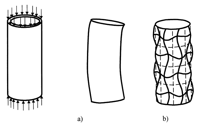
- Composite column buckling is a phenomenon in which the column, when subjected to axial compressive loads, fails by sudden lateral deflection rather than by yielding or crushing. The buckling phenomenon is given in Fig.33.
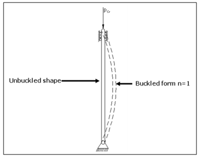 | Figure 33. Buckling Phenomenon |
 | Figure 34. Classical buckling theory |
3.2. Geometric Details
- Length of the Cylinder = 600mmDiameter of the Cylinder = 300mm
3.3. Design Loads
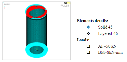
- Axial Force (AF) = 50kNBending Moment (BM) = 8 kN-mEquivalent axial compressive force = A.F+2 B.M/R = 50+ (2*8/0.150) = 156 kN
3.4. Design of Composite Shell
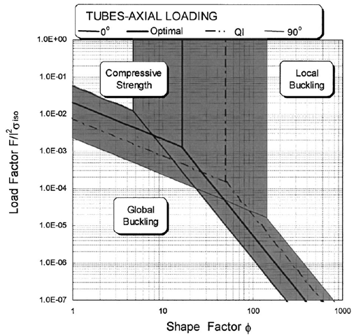
- A column loaded in compression, buckles when the load Fcr exceeds the load
 | (1) |
 | (2) |
 | (3) |
 | Figure 35. Axial compression of cylindrical tube buckling a) Elastic buckling b) Local buckling |
 | Figure 36. Failure mode Vs shape factor |
3.5. Selection of Composite Cylinder Thickness
- Based on formulae
 P = load applied = 156 K NA = cross sectional area of cylinderE = Young’s ModulusI = Moment of inertiaL = length of the cylinderBuckling Factor (BF) = 3From the above Equation, The thickness t=0.99 mm
3.6. Ply Skin Thickness
- Keeping manufacturing difficulties, the skin thickness selected is 1.2 mm. The number plies required are 1. Hoop windings = 4 [each layer thickness 0.2 mm, total thickness 0.8 mm] [3 Layers of CFRP T-700 and One Layer with CFRP+CNF (0.2 mm) outer Layer]2. Helical windings = 2 [each layer thickness 0.6 mm, total thickness 1.2 mm]Stacking sequence of laminate (90, ±30, 90, 90, ±30, 90)Total cylinder Skin thickness = 1.2+0.8= 2 mm.
4. Finite Element Analysis
4.1. Introduction
- Finite Element Analysis (FEA) is a computer-based numerical technique for calculating the strength and behaviour of engineering structures. It can be used to calculate deflection, stress, vibration, buckling behaviour and many other phenomena. It also can be used to analyze either small or large-scale deflection under loading or applied displacement. It uses a numerical technique called the finite element method (FEM). In finite element method, the actual continuum is represented by the finite elements. These elements are considered to be joined at specified joints called nodes or nodal points. As the actual variation of the field variable (like displacement, temperature and pressure or velocity) inside the continuum is not known, the variation of the field variable inside a finite element is approximated by a simple function. The approximating functions are also called as interpolation models and are defined in terms of field variable at the nodes. When the equilibrium equations for the whole continuum are known, the unknowns will be the nodal values of the field variable. In this project finite element analysis was carried out using the FEA software ANSYS. The primary unknowns in this structural analysis are displacements and other quantities, such as strains, stresses, and reaction forces, are then derived from the nodal displacements.
4.2. Buckling Analysis
- Buckling analysis is a technique used to determine buck ling loads (critical loads) at which a structure becomes unstable, and buckled mode shapes (The characteristic shape associated with a structure's buckled response). For thin walled shafts, the failure mode under an applied torque is torsional buckling rather than material failure. For a realistic driveshaft system, improved lateral stability characteristics must be achieved together with improved torque carrying capabilities. The dominant failure mode, torsional buckling, is strongly dependent on fiber orientation angles and ply stacking sequentTypes of Buckling Analysis:Two techniques are available in ANSYS for predicting the buckling load and buckling mode shape of a structure.They are,I. Nonlinear buckling analysis andII. Eigen value (or linear) buckling analysis.I. Nonlinear Buckling Analysis: Nonlinear buckling analysis is usually the more accurate approach and is therefore recommended for design or evaluation of actual structures. This technique employs a nonlinear static analysis with gradually increasing loads to seek the load level at which your structure becomes unstable. Using the nonlinear technique, model will include features such as initial imperfections, plastic behaviour, gaps, and large-deflection response.II. Eigen value Buckling Analysis: Eigen value buckling analysis predicts the theoretical buckling strength (the bifurcation point) of an ideal linear elastic structure. This method corresponds to the textbook approach to elastic buckling analysis: for instance, an Eigen value buckling analysis of a column will match the classical Euler solution. However, imperfections and nonlinearities prevent most real-world structures from achieving their theoretical elastic buckling strength.
4.3. FE Modelling
- A 3-D model was built for a composite cylinder using ANSYS 12.0 Finite-elements software. Initially one 30o sector was modelled and then the whole structure was generated using this primary sector. The global coordinate system of the cylinder is defined in such a way that the bottom face of the cylinder lies in the x- y plane and the positive z-axis is aligned with the axis of the cylinder. The following boundary conditions were imposed on the cylinder. The circumferential and radial displacements ‘v’ and ‘w’ respectively equal to zero at both faces of the cylinder (at z=0 and z=h, v=w=0). Axial displacement ‘u’ is zero at the bottom face of the cylinder but is non-zero at the top face where the load is applied (at z=0, u=0 and at z=h, u 0). The FE model and buckling mode shape is given in Fig.37 to 38.
 | Figure 37. Details of AF & BM |
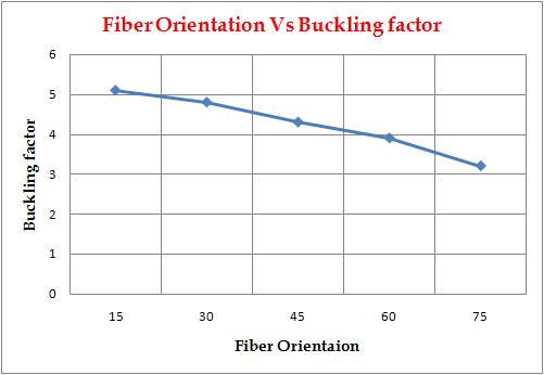 | Figure 38. Fiber Orientation |
5. Manufacturing of the Composite Shell
- Pop mandrel preparation as per given contour the cylinder is machined and Pop mandrel is shown in Fig.39.
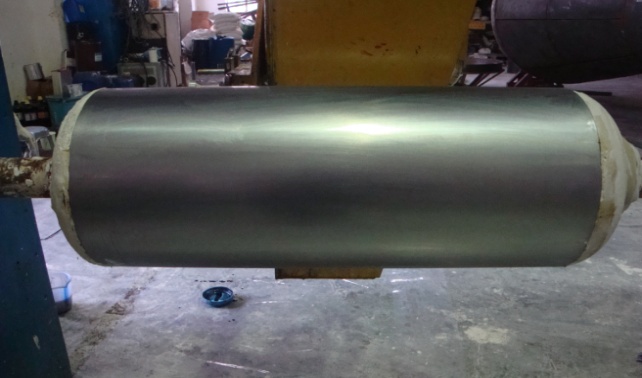 | Figure 39. Mandrel |
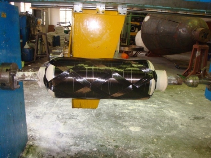 | Figure 40(a). Helical winding |
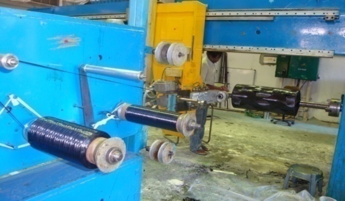 | Figure 40(b). Spool stand |
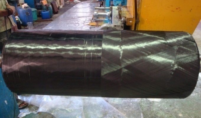 | Figure 41(c). Hoop winding |
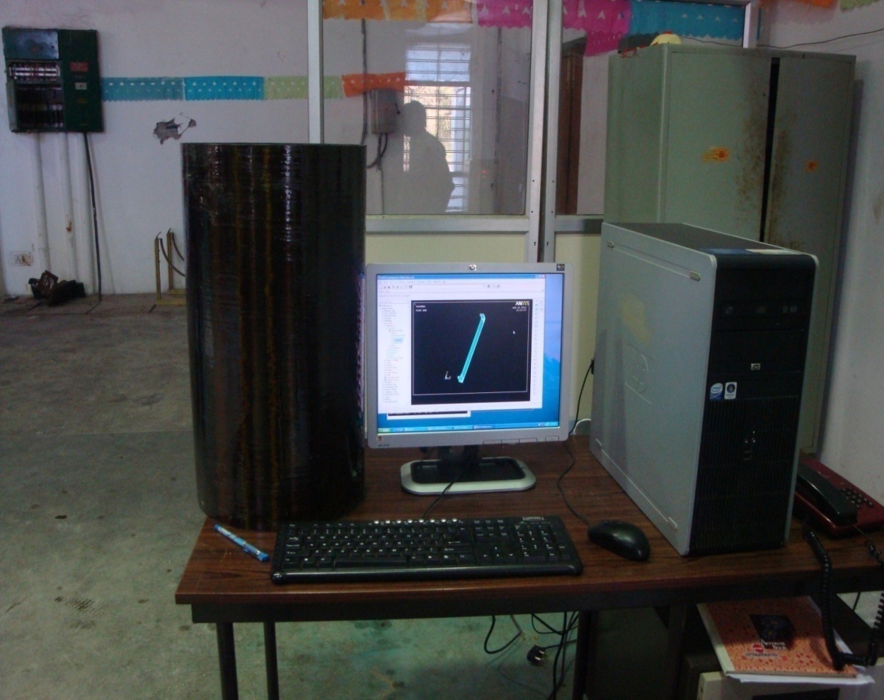 | Figure 42. Final component |
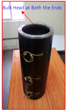 | Figure 43. Composite shell with end Bulkheads and Strain Gauges |
6. Experimental Validation and Testing
6.1. Testing of the Composite Cylinder
- The composite stiffened shell is assembled to test rig. The main objective of the testing are I. To measure the strains at specified load levels which in turn give corresponding stress/ strength levels.II. To measure the dilations / deformations of shell at various locations due to applied load.
6.2. Test Setup
- The test setup is as shown in Fig.44 the cylinder is tested with compressive loads applied at top surface of bulkhead to simulate the maximum flight load. To apply the simulated loads by actuators, one end of actuators are attached to I-sections and the other end of actuators is attached to rigid plate, which in turn placed on composite cylinder. The actuator loads are distributed through the rigid plate uniformly on the composite cylinder. The failed shell is given in Fig.44.
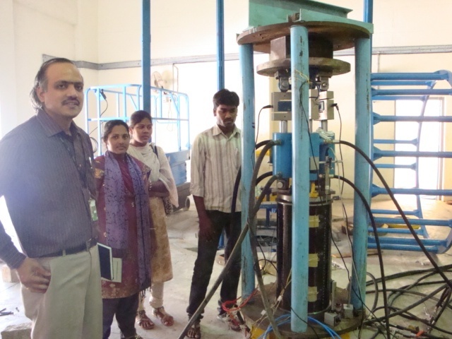 | Figure 44. Test Rig and Composite Cylinder Setup |
7. Results and Discussions
7.1. Static Analysis Results
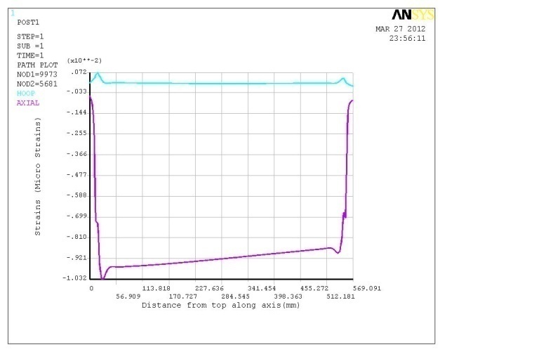
- The static analysis is carried out in the composite shell and details are placed in Fig.45 to 53
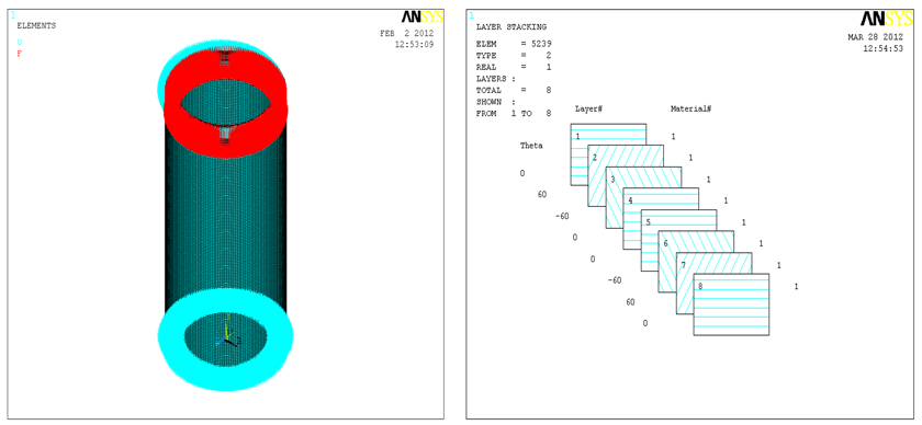 | Figure 45. FE model with loads & boundary conditions |
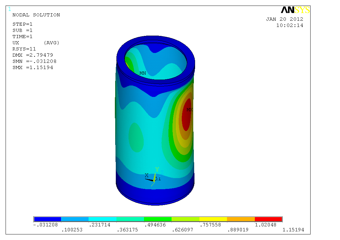 | Figure 46. Radial displacement plot |
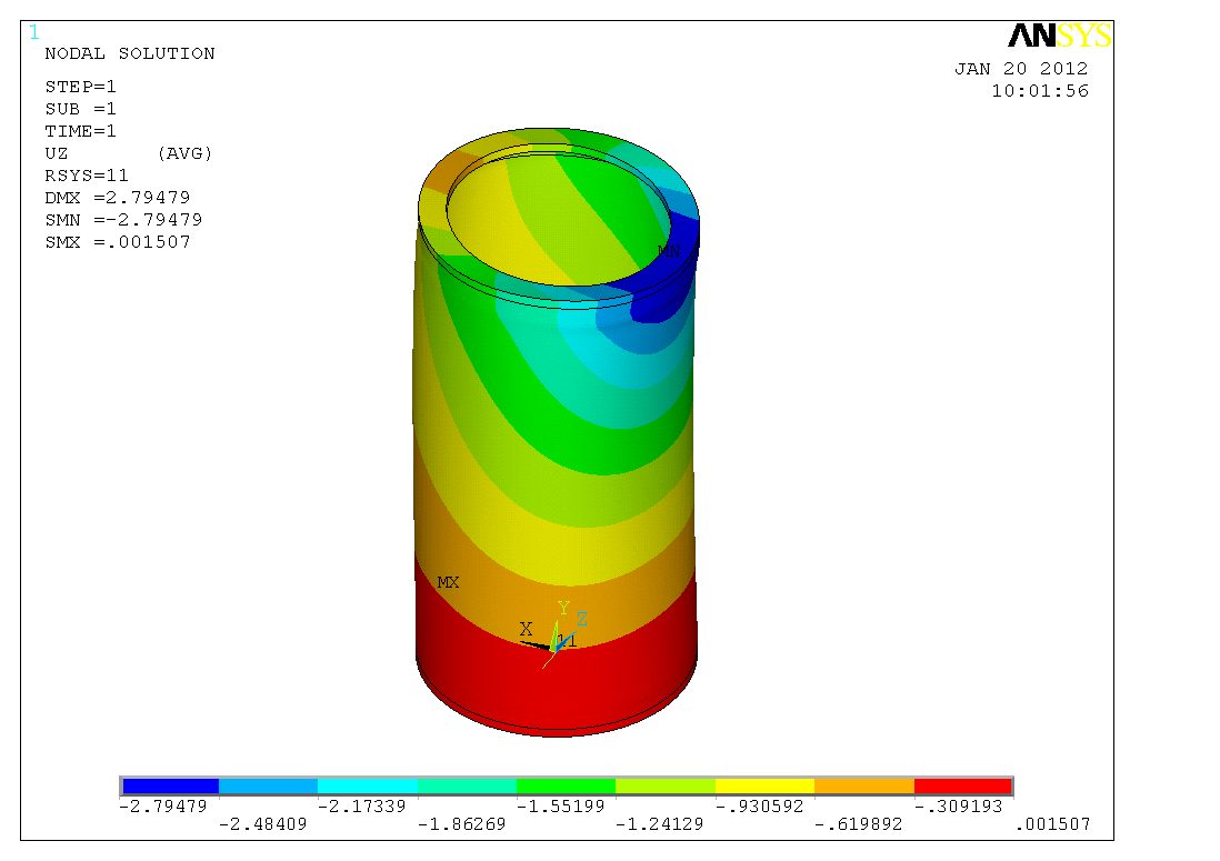 | Figure 47. Axial displacement plot |
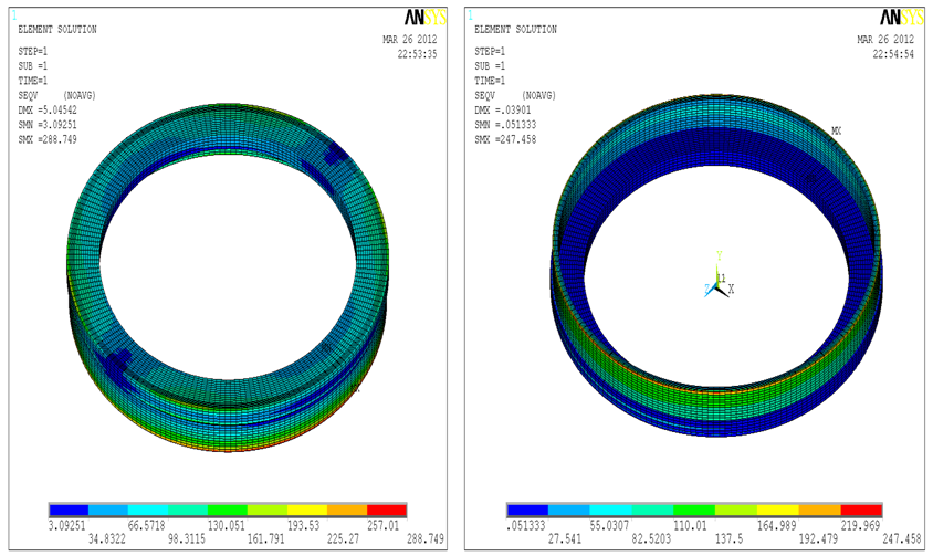 | Figure 48. Von-mises stress for Top ring and Bottom bulk heads |
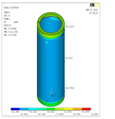 | Figure 49. Axial Stress plot |
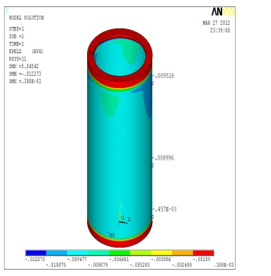 | Figure 50. Axial Strain plot |
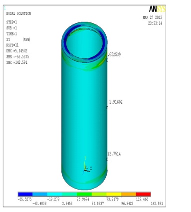 | Figure 51. Hoop Stress plot |
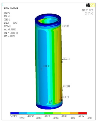 | Figure 52. Axial Strain plot |
 | Figure 53. Axial stress Layer wise plot |
7.2. Test Rig Results (Experimental Results)
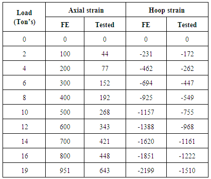
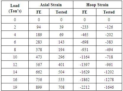
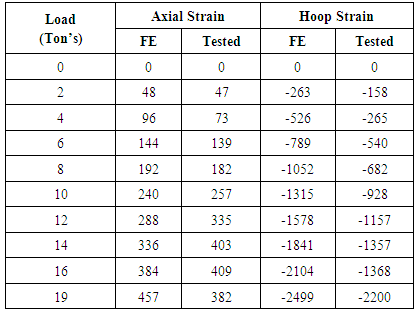
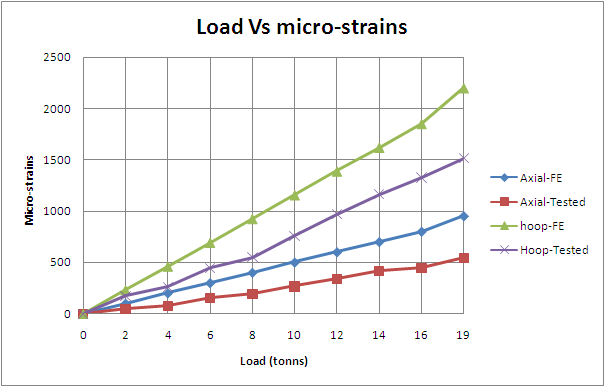
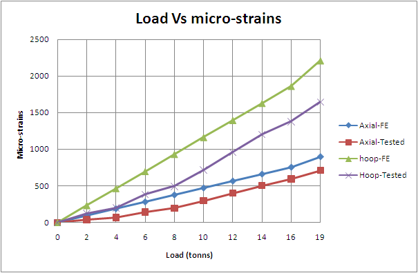
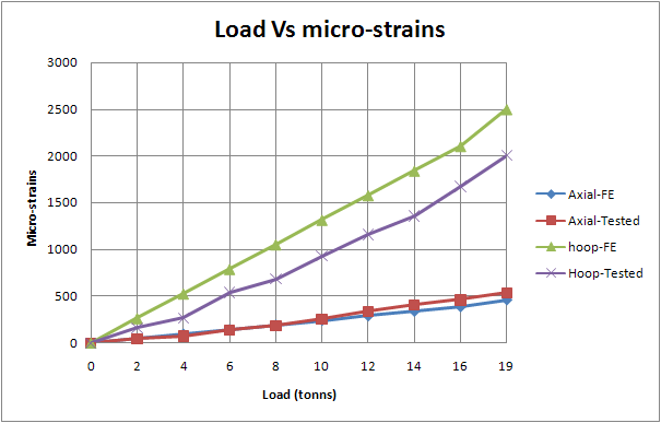
- The results are given based on load test performed on the actual composite cylinder with CNT. The four locations considered for testing. The strain comparison is given in Table 10 to 12. Also the detailed test results are given in Fig.54 to 56.
 | Figure 54. Strains at top of cylinder |
 | Figure 55. Strains at middle of cylinder |
 | Figure 56. Strains at bottom of cylinder |
7.2.1. Strain Details at Top of Cylinder
7.2.2. Strain Details at Middle of Cylinder
7.2.3. Strain Details at Bottom of Cylinder
7.3. Discussions
- In this study, Eigen value analysis is carried out to explore the linear buckling behaviour of composite cylindrical shells subject to axial compression. Linear buckling analysis, apart from its theoretical importance, is the basis for most of the available design guides and provides design engineers with an initial estimate of the buckling load for various configurations in early stages of design. This issue is particularly important in design of composite shells, where the number of design alternatives can make the design procedure very extensive.Composite cylinder failed by buckling mode at a load of 19 Tons and was observed to be a Shear failure of composite lower portion of shell. The buckled shell is shown in Fig.57.
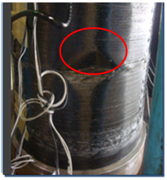 | Figure 57. The buckled shell |
7.4. Summary of Test Results
- Composite cylinders were fabricated & tested with buckling load conditions, the results are given in table 13. The Longitudinal Strength of CFRP with CNF is achieved 1860 MPa at Vf = 0.5. Therefore, the improvement against CFRP with epoxy resin (LY556) is 32%. Also the longitudinal modulus achieved is 118 GPa and improvement against CFRP with epoxy resin(LY556) is 10-15 %. Also Conductivity improved by 100%. The CFRP with CNF results comparison is given in Fig.58 to 59.
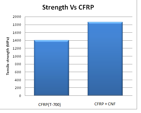 | Figure 58. Tensile strength comparison |
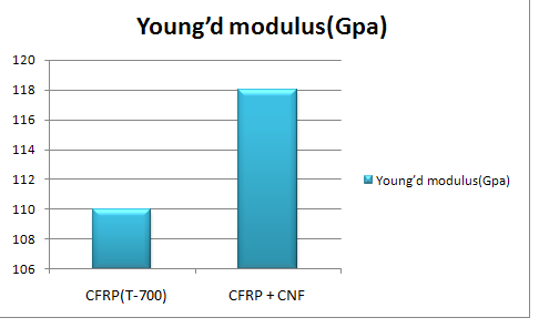 | Figure 59. Young’s Modulus comparison |
|
8. Conclusions
- Load testing of the composite cylinder has been conducted to verify the design and analyses procedure. It has been observed that the experimental results are in close agreement with the finite element analysis results. Also, the design stresses were within safe limits. Composite cylinders were fabricated & tested with buckling load conditions and based on test results, the Longitudinal Strength of CFRP with CNF is achieved 1860 MPa at Vf=0.5. Therefore, the improvement against CFRP with epoxy resin(LY556) is 32%. Also the longitudinal modulus achieved is 118 GPa and improvement against CFRP with epoxy resin(LY556) is 10-12%. Fracture toughness of CFRP with CNF is enhancing the structural behaviour, therefore fracture testing like mode-I, mode-II & Mode-III needs to be studied in future work.
ACKNOWLEDGEMENTS
- The authors gratefully acknowledge the laboratory Support extended by D.R.D.O, Advanced Technology Development, CPDC (ASL), Hyderabad.The authors also gratefully acknowledge to the Head of the Department, Mr. Rama swami (Scientist-F) CPDC, Hyderabad for his continuous Guidence and suggestions throughout my research work.Finally the authors also gratefully acknowledge to the management of M/s BEML Ltd and Department of Metro Production, Bangalore for their kind support at all the times.
 Abstract
 Reference
 Full-Text PDF
 Full-text HTML