Priyanka Brahmbhatt , Moni Banaudha , Subrata Pradhan
Institute for Plasma Research, Bhat, Gandhinagar, Gujarat, India
Correspondence to: Subrata Pradhan , Institute for Plasma Research, Bhat, Gandhinagar, Gujarat, India.
| Email: |  |
Copyright © 2012 Scientific & Academic Publishing. All Rights Reserved.
Abstract
Cyanate ester and epoxy blend have been identified as an attractive insulating material for fusion grade magnet winding packs. An insulation system comprising of fibre glass composites and cyanate ester blend has been analyzed during its vacuum pressure impregnation and curing. The transient one dimensional distribution of temperature and extent of cure has been evaluated both analytically and experimentally in this paper. The one dimensional transient (1-D) heat transfer characteristics evaluation has been carried out on 60:40 (epoxy: cyanate) which has been optimally prescribed blend for fusion grade winding process. The analytical formulation solves the heat transfer differential equations incorporating internal heat generation resulting from the exothermic chemical reaction in both chemical and diffusional kinetic regimes. In support to the analytical formulation, carefully designed experiments have been carried out on such samples. On comparing the results obtained from analytical formulism and those measured during experiments have been found to be matching well. These results have the potential to design the vacuum pressure impregnation of large size fusion relevant winding packs.
Keywords:
Composites, Differential scanning calorimetric, Kinetics molding, Resins
Cite this paper: Priyanka Brahmbhatt , Moni Banaudha , Subrata Pradhan , Temperature Distribution in Fibre-glass Composite Impregnated with Epoxy-Cyanate Ester Blend, International Journal of Composite Materials, Vol. 4 No. 1, 2014, pp. 38-44. doi: 10.5923/j.cmaterials.20140401.06.
1. Introduction
Magnet winding pack insulations employ appropriate thermosetting resin in a matrix of glass fibres. These insulation systems in an optimal vacuum pressure impregnation of the magnet winding pack, turns the magnet winding pack into a monolith of required mechanical and structural integrity that serves well against thermal and electromagnetic stresses. Additionally, the cured insulation system provides the required electrical break-down strength. Fusion relevant magnet winding packs have another critical requirement on the insulation to be radiation resistant against moderate neutron fluence. Cyanate ester resins based systems have been receiving increasing importance primarily because of their enhanced temperature and radiation resistance compared to conventional epoxy resins[1]. A special cyanate ester monomer has been suggested by European industry that is compatible with the existing industrial technique of vacuum pressure impregnation as required by ITER design[2]. Newly developed CE/Epoxy blend have been investigated in much detail under tension-tension fatigue load in view of the pulsed operating conditions of ITER and the results proved radiation resistant fatigue performance even at ITER relevant neutron fluence[3]. The insulation samples following 60:40 (DGEBF : CE) ratio in manganese acetyl acetonate in nonylphenol as catalyst and co-catalyst respectively had been exposed to 2 X 10²² m-2 (E>0.1 MeV), which was done in TRIGA reactor (Vienna) at ambient temperature. The 60:40 blend systems has shown less than 20% of reduction in mechanical properties. Therefore this blend system has been recommended as a candidate insulating system for ITER magnets[4]. The primary objective is to determine temperature field of thick thermoset laminates impregnated with epoxy-cyanate ester blend (60:40) manufactured by vacuum pressure impregnation process both through experiments and analysis. The interesting aspect with this composite has been the temperature overshoot at the centre of the composite due to the exothermaic nature of the reaction of the blend. The heat dissipation rate is quite slow due to the low thermal conductivity of the matrix. This has the potential to cause severe damage to the internal part of the insulation; this leading to the delamination of the insulation characteristics. This study has been motivated at determining the overshoot temperature at the centre of the composite for the particular cure cycle adopted. This in turn would help for the determination of the cure cycle. For this purpose heat conduction equation has been combined with the cure kinetic equations for determining the temperature profile across the insulation system. Cyanate ester additionally functions as a hardner to cure epoxy resin that produces highly cross linked thermosets. The conversion from the liquid state of monomers or oligomers having low molecular weight to three dimensionally networked rigid materials is accompanied with highly exothermic processes. The cured system gets formed as an infinite network extending to all spatial directions that hinders molecular movement. Cyanurate (triazine) is formed through the trimerization of CE. Insertion of glycidyl ether epoxide into aryl cyanurate results in rearrangement of the aryl cyanurate into alkyl isocyanurate. Oxazoline and oxazolidinone are then formed depending on the cure conditions. Thus, the overall reaction can be considered happening in two steps: Cyclotrimerization of CE to produce triazine rings as the intermediate product and coreaction of epoxy and triazine rings to form oxazolidinone rings at higher temperature. The curing reaction between cyanate ester and epoxy resin have been proposed by Bauer pathways as shown in figure 1[5].The laminates impregnated with resin are subjected to external heating in a typical vacuum pressure impregnation curing process. The temperature of external layers increases rapidly than the inner ones. As the curing progresses, the temperature of the inner becomes higher than the external surface of laminates due to exothermic nature of the matrix. The curing temperature is decided by carrying out the differential scanning calorimeter experiments on the intended blend system of epoxy and cyanate ester as shown in figure 2. As the epoxy resin cures, the –OCN groups take part in the trimerization reaction to form structure with high cross-linking density. This causes the temperature variation in the laminates due to liberation of energy. This leads to introduction of microscopic defects such as voids, bubbles and weak adhesion with fibres. Therefore, the curing temperature of the matrix is necessarily to be optimized so that void free laminates are obtained.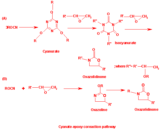 | Figure 1. Reaction scheme for copolymerization of cyanate and epoxy |
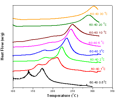 | Figure 2. DSC scans 60:40 (epoxy: cyanate) at heating rates 0.5℃/min, 1℃/min, 2℃/min, 3 0C/min, 5℃/min, 10℃/min, 20℃/min, and 30℃/min (with catalyst) |
2. Thermo-chemical Model
The reaction kinetics and the curing have been explained with the help of thermo-chemical model. The model is based on a one dimensional model of heat transfer. The heat transfer modelling includes the internal heat generation due to chemical reaction kinetics according for chemical and diffusional control effects.Following assumption have been adopted in order to develop the thermo-chemical model:1. Convective heat transfer effect caused by the resin flow during impregnation process is negligible.2. Epoxy-cyanate blend system is well mixed and is homogeneous.3. The temperature of the impregnation mould wall is kept constant throughout the curing process which is a practical situation.Neglecting energy transfer by convection and heat conduction in planar directions, the equations of energy and species balance can be expressed as[6,7],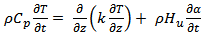 | (1) |
Where, T is temperature, ‘ρ' is the density of the composite‘Cp’ is the specific heat of composite‘k’ is the thermal conductivity of the composite ‘Hu’ is the enthalpy (heat generation during the reaction).A number of kinetic models have been proposed on the basis of empirical rate laws to describe the curing process of thermosetting systems. Extent of curing rate can be explained as a function of degree of cure. Both ‘n’th order and bimodal have been proposed towards modelling cure kinetics of thermosetting materials. The ‘nth’ order kinetics is expressed as[8], kinetics of thermosetting materials. The nth order kinetics is expressed as[8],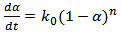 | (2) |
The cure kinetic equation (3), written below is the autocatalytic type. The rate constant is expressed by Arrhenius function. The same has been chosen to fit the kinetic data same the reaction spreads over both chemical and diffusion control mechanism regimes.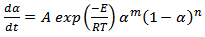 | (3) |
Here ‘A’ is the frequency factor and ‘E’, is the activation energy. The blend comprising of epoxy and cyanate ester starts to become gel as the reaction proceeds simultaneously more and more conversion occurs. During the entire processes, the ‘heat of reaction’ gets released first vigorously in the ‘chemical regime’ of reaction followed by ‘diffusion regime’ of reaction[9]. The rate of heat generation becomes lesser as the reaction proceeds.These reactions are best described as a two-step plateau kinetic model. The first step corresponds to chemical controlled regime and the second one refers to diffusion controlled regimes[10]. The overall (CE + Epoxy) described as,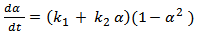 | (4) |
Where, where ‘α’ denotes the conversion of cyanate groups and ‘k1’ and ‘k2’ are empirical rate constants. The plot of  against conversion for CE and epoxy blend as investigated by us shows that the curve is flat. It is further horizontal and parallel to the x-axis with negligible slope. This indicates that k2 ≈ 0 10. It further proves that the order of reactions is no more quadrate but of higher order. This result prompts us to look for an explanation of a variable “n” kinetic model. These two steps of reactions of nth order (chemical and diffusion) are indicated as nth order, therefore can be written as,
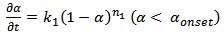 | (5) |
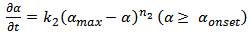 | (6) |
Where, “k1” and “k2” are the rate constants in chemically controlled regime and diffusional controlled regimes respectively. “n1” and “n2” are the order of reaction in the above regimes. “αmax” is the saturated plateau conversion and “αonset” is the transition of “α” between chemical kinetic regime to that of the diffusion controlled regime.Alternatively, thermosetting reaction can be explained ab-initio by considering the overall rate constant of the reactions that comprises of two rate constants. These rate constants refer to that of chemical kinetics domain and of diffusion kinetic domain respectively.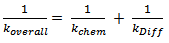 | (7) |
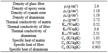
Here, ‘kchem’ is chemical controlled regime rate constant obeying Arrhenius equation (prior to vitrification), ‘kDiff’ is the diffusion regime rate constant as a function of curing temperature and conversion (α)[10].Table 1. Physical-chemical properties of the epoxy-cyanate ester composite
 |
| |
|
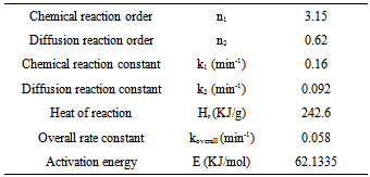
The cure kinetic model of the epoxy-cyanate ester blend was obtained from the data as obtained from Perkin Elmer. Curing kinetic study was performed using an isothermal scanning. The extent of conversion as a function of time has been obtained from isothermal DSC scan carried out at 160℃ in this investigation. The extent of curing in polymerization reaction is never been complete conversion as the isothermal DSC scan were carried out at low temperature. The dynamic DSC test was also performed at 10 K/min as shown in fig.2. The cure kinetic model has been developed by using equation (1) and (3). Physical properties and cure kinetic parameters have been shown in Table I & II respectively. The transverse conductivity has been calculated using the following Tsai-Halpin model.Table 2. Cure kinetic parameters of the matrix[10]
 |
| |
|
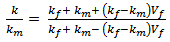 | (5) |
Where, ‘km’ is the conductivity of resin, ‘kf’ is the fibre conductivity in the transverse direction of fibre; ‘Vf’ is the fibre volume fraction of composite[11].AnalysisThe thermo-kinetic model has been solved using the following boundary conditions (Fig.3),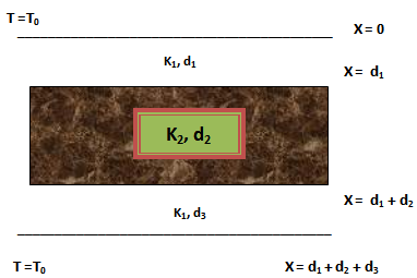 | Figure 3. composite slabs between two aluminium plates showing the imposed temperature on the two sides |
t = 0, z = 0, α = 0, T(z) = T0, 0 ≤ z ≤ c,t > 0, z = 0, T = Tc,t > 0, z = c, T = Tc,t > 0, z = h/2, T = T(t),、Where, ‘T0’ is the initial temperature, ‘Tc’, curing temperature, ‘h/2’ the centre of the laminate. First the expression for boundary medium, aluminium plates had been formed and analysed. The aluminium plates have been assumed to be at a uniform temperature ‘Ti’, the boundary surfaces of the plate at bottom are kept insulated. This surface is in contact with fibres and the temperature of top surface is then raised to a constant curing temperature (Tc) for t>0. The second expression has been formulated for the composite material. The composite has been initially at a uniform temperature ‘Ti’ at time t=0. Suddenly both the surfaces were raised to the constant temperature for t>0 as it is in a practical impregnation process. Both the expressions have been solved simultaneously and the analysis has been carried out. The laminates have been placed between two aluminium plates as shown in fig.III. The contact between the interfaces is assumed to be thermally perfect in this the configuration.Where, Let K1 and K2 be thermal conductivities of aluminium plates and composite respectively. d1 (5 mm), d2 (25 mm) and d3 (30 mm) be the thickness of the first, second and third layer.
3. Experimental
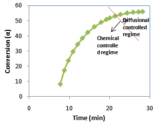 | Figure 4. Experimental data of conversion versus curing time for epoxy: cyanate blend system |
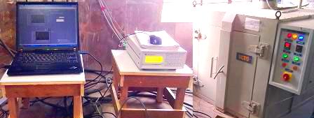
The fibre reinforcement with matrix has been carried out to verify the analytical model with the experiment results as well as cure cycle. The unidirectional glass fibre laminates (thickness = 20 mm) were stacked between two aluminium plates (thickness = 5mm) covered by released film. The autoclave temperature was increased to 160℃with the rate of 10℃/min. The distribution of temperature was measured by placing thermocouples at the centre and the surface of the laminates. Experimental curves of conversion (α) against curing time (t) at isothermal curing temperatures at 160℃ for the 60:40 (epoxy: cyanate) blend system are shown in Fig.4. The resin was mixed with catalyst and placed in the injection pot. The resin was injected in to the mold and the fibres were soaked in the resin for 10 min. In order to measure temperature profile in the composite with respect to time, the evolution of the temperature was monitored at three different locations with the bare type of PT-100 thermocouples. Two thermocouples were situated at the wall of the two aluminium plates and the other third one was placed at the centre of the composite. The thermally sensitive region of thermocouple was placed parallel to glass fibre and was completely shielded from the autoclave exposure so that it could only measure the composite temperature instead of autoclave temperature. The configuration of fixing the thermocouple in the composite has been shown in figure 5. The PT-100 thermocouples were connected to the Lakshore temperature monitor. The signals from the wires were recorded on a computer through a data acquisition system. The composite was placed in the oven and the temperature measurement was carried out for 30 min. Experimental set up has been shown in figure. 6 in which temperature monitor was connected to the system through thermocouples. Laminates have been observed as a solid monolithic structure after impregnation as shown in figure 7.The solid line is an arbitrary division of chemical controlled and diffusion-controlled regions as shown in figure 4 particular to this reaction.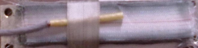 | Figure 5. Thermocouple fixed up at the centre of the composite |
 | Figure 6. Experimental set up |
4. Results and Discussion
The temperature field measurement at three locations was done experimentally and the results have been compared with the analytical solutions obtained from the mold as shown in Fig.8. The measure temperature field distribution is in good agreement with the analytical solution. An overshoot in the temperature profile has been observed in the experimental results. The maximum temperature at the centre of the laminate is measured to be 261℃ when the walls are kept at 160℃. As the exothermic reaction begins the temperature at the centre becomes higher than oven temperature due to internal heat generation. The centre temperature of the laminates increases consequently. The heat does not get dissipated to the walls fast enough since the thermal conductivity of the fibre matrix is low. The centre temperature keeps on increasing and attains a particular value for a particular curing schedule. The analytical peak is shown to be slightly shifted towards left of the graph. It is further slightly lower than the experimental peak. This indicates the reaction occurred earlier in time from analytical simulation. This discrepancy is attributed to the approximation made on the thermo-physical properties of matrix, fibres and the mould. The thermal conductivity and heat capacity were assumed to be constant throughout the curing process. However, it varies somewhat while transformating from liquid state to solid state[12]. The peak temperature was found to be higher repeatedly in several trials made. It was further very consistent for a fixed ration of CE:Epoxy (60:40) and curing schedule.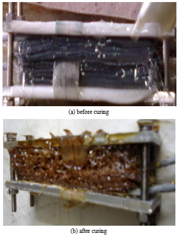 | Figure 7. Composite before and after curing |
5. Conclusions
The temperature distribution and the degree of cure in the composites have been evaluated by using both one dimensional transient heat conduction adopting analytical methods and in an optimally designed experiment. An overshoot in the temperature profile at the centre of the laminate has been observed due to the exothermic chemical reaction involved with CE-Epoxy blend conversions. Non-uniformity in the temperature distribution throughout the thickness of the composite has been observed due to low thermal conductivity of the epoxy-cyanate blend. It has resulted in rate of heat dissipation in the composite. The maximum overshoot temperature should not be higher than the glass transition temperature of the matrix for a blend system during impregnation results in the degradation of fibers and matrix. It can lead to non-uniform distribution of the residual stress and can render the cured system mechanically unstable. An optimal curing cycle in an impregnation is a mandatory to preserve the monolith and mechanical integrity of the insulation system.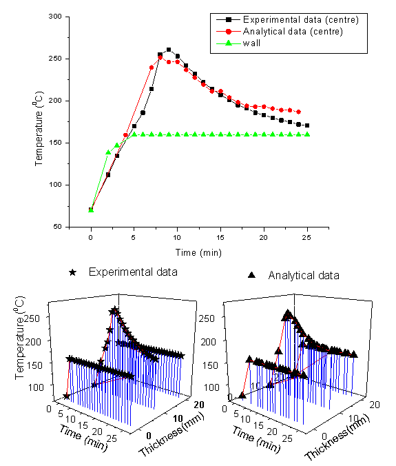 | Figure 8. Temperature profile at the centre and surface of the composite |
References
| [1] | Prokopec, R., Humer, K., Maix, R., Fillunge, H., Weber, H. : Characterization of advanced cyanate ester/epoxy insulation systems before and after reactor irradiation. Fusion Engineering and Design. 85, 227-233(2010). |
| [2] | Humer, K., Bittner-Rohrhofer K., et al. : Radiation effects on the mechanical properties of insulators for fusion mangents. Fusion Engineering and Design. 81, 2433-2441 (2006). |
| [3] | Humer, K., Bittner-Rohrhofer, K., Fillunger,H., Maix, R. et al. :Innovative insulation systems for superconducting fusion magnets.Superconducting Science Technology. 19, S96-S101 (2006). |
| [4] | Humer, K., Bitter-Rohrhofer, K., Fillunger, H., Weber, H. : Mechanical strength of various cyanate ester/epoxy insulation systems after fast neutron irradiation to the ITER design fluence and beyond. Fusion engineering and design, 82, 1508-1512. |
| [5] | Pradhan, S., Brahmbhatt, P., Sudha, J., Unnikrishnan, J. : Infulence of manganese acetyl acetonate on the cure-kinetic parameters of cyanate ester-epoxy blend systems in fusion relevant magnets winding packs. Journal of Thermal analysis and Calorimetry. 105, 301-311(2011). |
| [6] | Hojjati, M., Hoa, SV.: Curing simulation of thick thermosetting composites. Composite Manufacturing.5 (3), 159-169. |
| [7] | Young, W,. : Compacting pressure and cure cycle for processing of thick composite laminates. Composite Science and Technology. 54,299-306 (1995). |
| [8] | Yi, S., Hilton, H., Ahmad, M. : A Finite Element Approach for Cure Simulation of Thermosetting Matrix Composites. Computers & Structures. 64, 383-388(1997). |
| [9] | Tai, H., Chou, H. : Chemical shrinkage and diffusion controlled reaction of an epoxy molding compound. European Polymer Journal. 36, 2213-2219(2000). |
| [10] | Brahmbhatt, P., Unnikrishnan, J., Sudha, J., Pradhan, S. : Cure Kinetic Studies of Cyanate ester and Bishpenol-F Epoxy blend. Journal of Applied Polymer Science (2011). DOI:10.1002/app.34419. |
| [11] | Guo, Z., Du, S., Zhang, B.: Temperature field of thick thermoset composite laminate during cure process. Composite science and Technology.65, 517-523. |
| [12] | Rouison, D., Sain, M., Couturier, M.: Resin transfer molding of hemp fiber composites: optimization of the process and mechanical properties of the materials. Composite Science and Technology. 66, 895-906(2006). |
 Abstract
 Reference
 Full-Text PDF
 Full-text HTML