P. A. Lyukshin1, B. A. Lyukshin1, 2, N. Yu. Matolygina1, S. V. Panin1, 3
1Inst Strength Phys & Mat Sci SB RAS, Tomsk, Russia
2Tomsk Univ Control Syst & Radioelect, Tomsk, Russia
3Tomsk Polytechnic University, Tomsk, Russia
Correspondence to: B. A. Lyukshin, Inst Strength Phys & Mat Sci SB RAS, Tomsk, Russia.
| Email: |  |
Copyright © 2014 Scientific & Academic Publishing. All Rights Reserved.
Abstract
Deformation behavior of thermal barrier coatings was studied by means of computer aided design. The mechanism of instabilities to occur in such coatings was studied based upon their representation in the form of a plate located on an elastic foundation. Stability loss manifests itself in the form of a double periodic system of intrusion and extrusion zones that is qualitatively consistent with the well-known experimental results. Typical features of the stability loss and its dependence on the properties of interfaced materials were investigated by simulating thermal loading of a copper specimen with a protective ceramic coating. The influence of the anisotropy of thermal-mechanical properties of the coating material on the character of the instability occurrence was estimated.
Keywords:
Thermal barrier coating, Anisotropy, Heat impact, Computational mechanics, Thermal stress and deformation, Stability loss
Cite this paper: P. A. Lyukshin, B. A. Lyukshin, N. Yu. Matolygina, S. V. Panin, Stress-Strain State and Stability Loss of Anisotropic Thermal Bаrrier Coating under Thermal Impact, International Journal of Composite Materials, Vol. 4 No. 5A, 2014, pp. 16-26. doi: 10.5923/j.cmaterials.201401.03.
1. Introduction
Relevance of the problem on research of thermal barrier coatings (TBC) [1-5] is related both to the intensive use of TBC for power engineering as well as to the permanent search for new materials whose use can raise equipment life-time at elevated operating temperatures. In doing so, TBC is an object that must protect the substrate from high temperature impact; if this takes place it possesses high adhesion, heat resistance, and ability to keep operating properties under multiple cyclic thermo-mechanical loads. Studies of TBC including simulation of their deformation behavior under the influence of operating loads are oriented towards identification the mechanisms and regularities of their fracture and improved design.The main problem under TBC operation is related to the difference in thermal characteristics, primarily the linear thermal expansion coefficient (LTEC) of brittle ceramic coating and ductile substrate. Under heating there happens deformation of the latter that is significantly higher in contrast with one of the coating that leads to the appearance of powerful stress concentrators at the interface whose relaxation occurs by cracking. In general, this problem can be diminished to a difference in the elastic moduli of two interfaced media. In doing so, the simulation of their deformation can be carried out for the case of a layered composite that is well worked out in the framework of the elasticity theory [6].The calculation of the stress distribution at the interface between two grains in elastically loaded crystal was carried out by Yu.V. Grinyaev [7]. It was shown that the distribution has a periodic oscillatory pattern with a maximum in the middle of the double joint and the gradual stress decay towards the edge of the grain. An important result concerning the periodic solutions for thermal loading of a thin film on a solid substrate is presented by G.P. Cherepanov [8]. It is noted that the distribution of stresses in such a system is a sine- and cosine-type function that depends on the film thickness.Development of these results to the case of two-dimensional distribution was considered in the study of O.I. Cherepanov where behavior of thin shells was simulated [9]. A regular two-dimensional strain distribution was observed there whose formation is related to the stability loss. Visual experimental confirmation of the "chessboard-like" distribution of stresses and strains during thermal cycling of the copper specimen with nanostructured thermal barrier coating is given by V.E. Panin [10]. It is a confirmation of the concept of similarity of mass transfer processes that develops in the objects of organic and inorganic nature that might have periodic (chessboard-like) distribution [11].In this paper, the occurrence of instabilities with periodic character was obtained under calculation performed with the use of classical approaches of solid mechanics. The object under study was thermally loaded copper specimen with a ceramic coating. The parametrical calculations were carried out to estimate the influence of the properties of interfaced materials, including the anisotropy of the deformation and strength properties of the coating.The following stages of analysis were employed: i) the calculation of the temperature distribution in the coating and the substrate in transitional regime under the influence of thermal impact; ii) estimation of parameters of the stress-strain state of the coating under the influence of thermal loads; iii) simulation of the stability loss process at calculations for different geometrical and stiffness parameters of the coating and substrate; iv) evaluation of stresses in the coating after the stability loss.
2. Description of Model’s Parameters
In the plane formulation the computational area under analysis to include a substrate ABCF and thermal barrier coating CDEF (Figure 1), is subjected to intense heating (thermal impact) being applied to the surface ED. It is assumed that the thickness of the coating and the substrate AFE = BCD are much smaller of two other linear dimensions. Characteristics of aluminum oxide (Al2O3), and copper (Cu) were used for specifying the material of thermal barrier coating CDEF and one of the substrate ABCF, consequently. 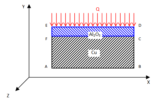 | Figure 1. Configuration of a computational area |
For alumina specific heat С = 1106 J/kg•grad, density ρ = 3970 kg/m3, the coefficients of thermal conductivity in the direction of the x and y axes made Кхх = Куу = 40 W/m•grad. As for copper, the specific heat C = 380 J/kg•grad, density ρ = 8900 kg/m3, the coefficients of thermal conductivity were Кхх = Куу = 385 W/m•grad.
3. Solution of the Thermal Conductivity Problem
To determine the temperature field by the finite elements method (FEM) [12-14] the non-stationary thermal conductivity problem for the ABCDEF area is solved. At the boundary of materials with different physical and mechanical properties (line FC) conditions of ideal thermal contact were applied: in particular equality of temperature and heat flows [12]. Symmetry conditions were put at the edges of AE and BD: 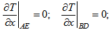 | (1) |
Formulation of these conditions reflects the fact that the boundaries imposed by AE and BD lines artificially limit the size of the region to be analyzed, as in a real situation interfaced area has exactly the same characteristics as the design. Dirichlet conditions are set at the AB and ED edges: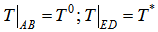 | (2) |
It is assumed that at the moment t = 0, the temperature in the entire ABCDEF region was constant and equal to the initial value: | (3) |
When solving the problem by FEM heat equation with the boundary conditions (1) and (2) are reduced to minimize the functional [13]: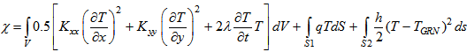 | (4) |
where S1 – surface area where the heat flow is given;S2 – surface area, where the convective heat exchange takes place;Kxx, Kyy – coefficients of thermal conductivity;Т – temperature;λ = с•ρ, с –specific heat, ρ – density;V – volume of the specimen;q – heat flow;h – coefficient of heat transfer;TGRN – ambient temperature.The mesh of finite elements comprises 7200 elements and 3721 node. When solving the problem of the temperature distribution in the computational area a system of linear algebraic equations (SLAE) corresponding to this mesh contains 3721 equations. Non-stationary heat conductivity problem is solved by an implicit scheme [12]. The temperature field and isolines in the computational area at the time t = 0.05 s are shown in Figure 2 The coating thickness was 500 µm, while the substrate one – 0.011 m.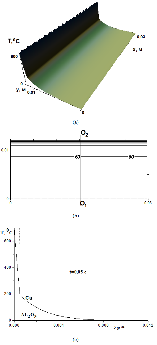 | Figure 2. а) Surface illustrating temperature distribution, b) isolines of temperature at the time t = 0.05 s, c) temperature change in the center of the plate (curve О2О1) at the time t=0.05 s, coordinate yS is measured from point О2 to point О1 |
4. Calculation of Temperature, Deformations and Stresses in an Anisotropic Medium
To calculate the stress-strain state in the computational area the finite element method is used. To do this, the potential energy of an elastic body is stored when it is subjected to surface forces Px, Py, Pz in the presence of initial deformations ε0 as the energy functional П, under condition of its minimum where
where  – displacement vector, a system of linear algebraic equations is obtained
  where [K] – the global stiffness matrix of the mechanical system, {F} – vector of loads. The global stiffness matrix of the finite element mesh is the sum of stiffness matrices of individual elements:
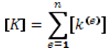 and stiffness matrix for an individual element can be written as:
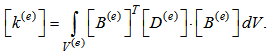 Global force vector {F} is the vector sum of forces of individual elements {f(e)}
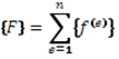 and the vector of forces of one finite element in the presence of surface forces Рх, Ру, Рz and initial deformations can be written as follows:
 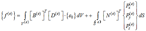 The vector of initial (temperature) deformation in the case of plane stress in the local coordinate system X1, Y1, coinciding with the axes of orthotropy, is:
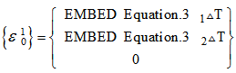 where λ1 , λ2 – thermal expansion coefficients along the axes of orthotropy О1Х1, О1У1, ΔТ – change of the temperature (heating, cooling) of a finite element.
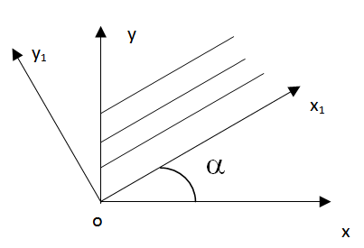 | Figure 3. The relative orientation of the global XOY and local X1ОY1 coordinate systems |
Thermal strain vector {ε0} in the global coordinate system OXY is associated with deformation vector  in the local coordinate system ОХ1У1 by relations [16]:
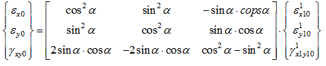 | (5) |
Equation (5) in a reduced form can be written as 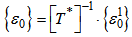 where
where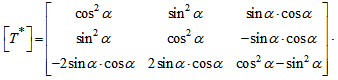 Matrix [T*] is called the transformation matrix for strains [15-17]. Hooke's law for an anisotropic material can be written as:
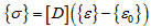 Matrix of elastic characteristics [D] in the case where the local axis (orthotropy) ОX1Y1 coincides with the global axes OXY is equal to:
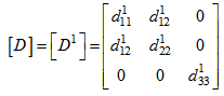 | (6) |
In formula (6) the values 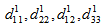 are respectively:
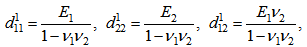
 . where Е1, Е2 – elastic moduli along axes Х1 , Y1; ν1, ν2 – Poisson's ratios; G – shear modulus.Matrix of elastic characteristics [D] in the case when the local axes (orthotropy) OH1Y1 do not coincide with the global axes OXY, and is equal to [17]:
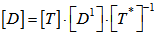 where [D1] – matrix of elastic properties in the local ОХ1Y1 axes, [T] – the strains transformation matrix [17]:
 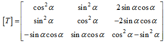 One should noticed that [T*]-1=[T]T, i.e. inverse matrix of strain transformation is the transposed matrix of strains transformation [17]. In view of the foregoing observations of the matrix of elastic characteristics can be represented as follows:
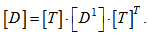 Consequently, the matrix of elastic properties of the anisotropic body will be completely filled and can be written as:
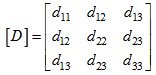 In the [D] matrix its elements are equal to:
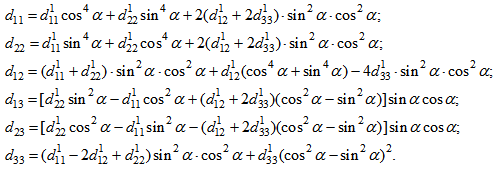 | (7) |
In the case of plane stress state of anisotropic medium the integral associated with thermal expansion (initial deformation), belongs to the force vector and is equal to [13]: | (8) |
Here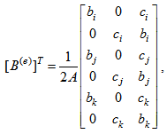 | (9) |
Where bi = y(i)-y(k), сi = x(k)-x(j). Coefficients bj, cj, bk, ck in (9) are obtained by cyclic substitution.Figure 4 a, b shows the surface of stresses σ11 and stress isolines corresponding to the temperature given in Figure 2. Figure 4, c also demonstrates a curve of stress changing σ11 along the line O2O1. The boundary conditions for solving the problem of the stress-strain state were specified. Displacement along the y axis on the AB line is equal to 0; displacement along the x-axis at the point O1 is equal to 0. 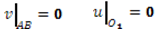
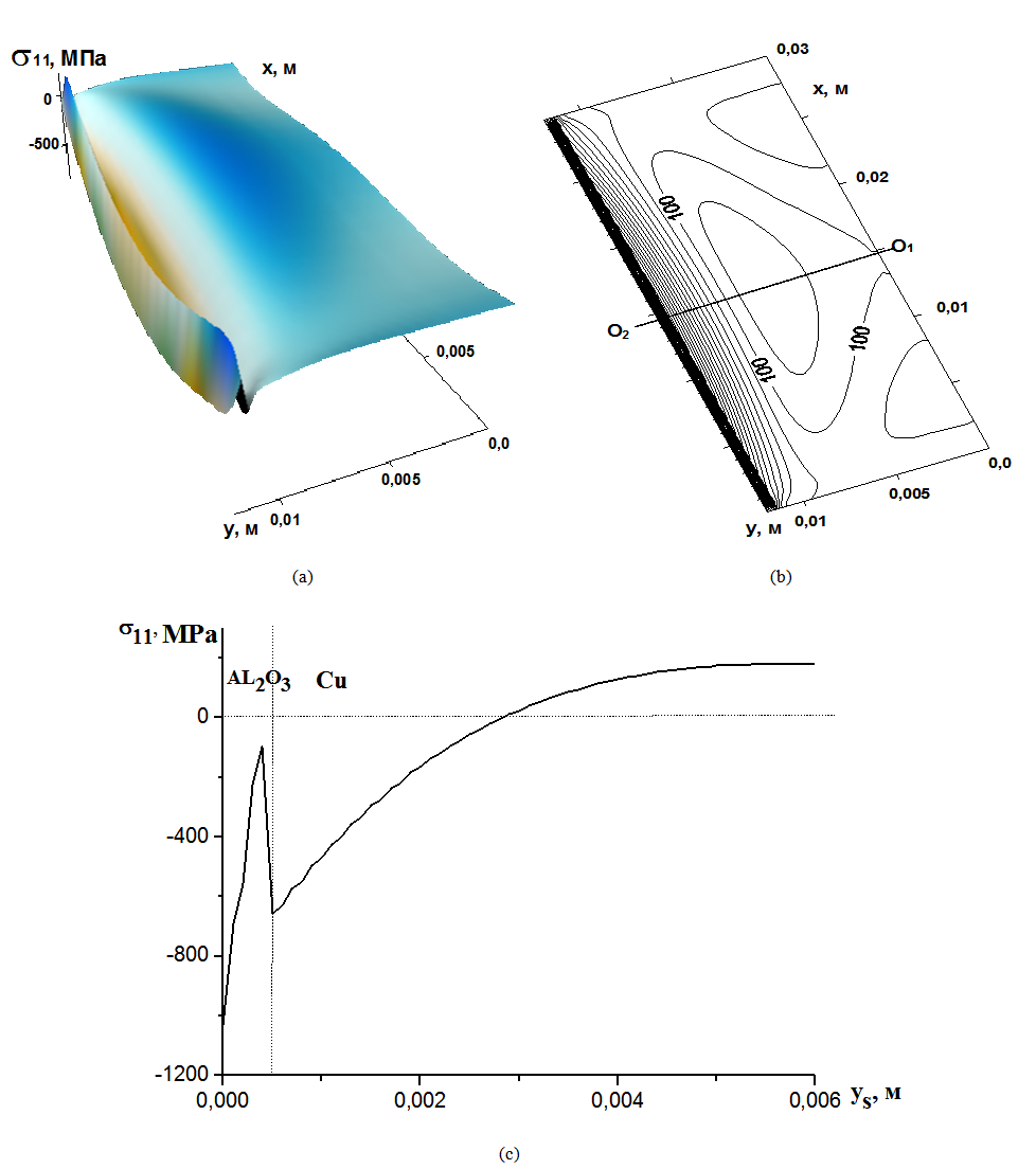 | Figure 4. а) Surface showing distribution of stresses σ11 in nonuniformly heated solid, b) isolines of stresses σ11 at t = 0.05 s, c) stress changing σ11 in the center of the plate (line О2О1) at t = 0.05 s, yS coordinate is measured from point О2 to point O1 |
5. Stability of a Thermal Barrier Coating
Aluminum oxide layer on the copper substrate is modeled as a plate on an elastic Winkler basis [15]. Stability equation of anisotropic plate onto elastic basis has the form [15, 16, 20]: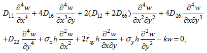 | (10) |
In equation (10) D11, D22, D12, D66, D16, D26, are, respectively,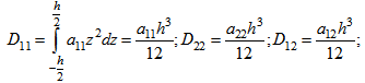
 where h - thickness of the plate. The coefficients а11, а22, …, а26 are included in the physical relations for the anisotropic plate to coupling stress and strain as follows [20]
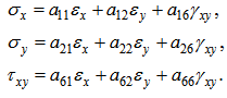 | (11) |
For an orthotropic material the coefficients а11, …, а66 in the case when the axis of material orthotropy X1,Y1 coincides with the global axes X, Y, are equal to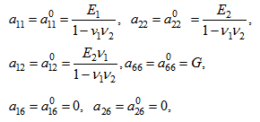 where Е1, Е2 – elastic moduli along х1 and у1 axes, ν1,ν2 – Poisson's ratios, G – shear modulus.For the case when orthotropy axes Х1, Y1 of a material constitute angle α with the global axes X, Y, the coefficients а11,…,а66 in (11) are converted analogously to coefficients d11,…,d33 in formula (7).Strain components εx,εy,γxy are related to the bending in the center of the surface w by the following relations:
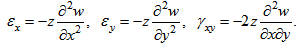 | (12) |
Appearing in (12) the value z is the distance from the center of the plate surface to the current point.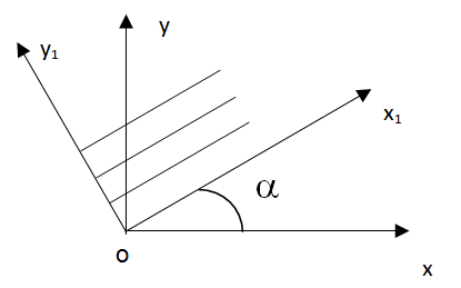 | Figure 5. Material orthotropy axis Х1, Y1 are rotated relative to the global axes X, Y at the angle α |
The homogeneous equation (10) can be solved together with the homogeneous boundary conditions. If edges of the plate are tightly clamped, the boundary conditions are: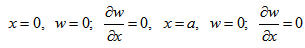 | (13) |
 | (14) |
Equations of stability (10) together with boundary conditions (13, 14) are a system of homogeneous differential equations in partial derivatives with homogeneous boundary conditions. The nontrivial condition for solution of the system of homogeneous equations determines the critical load of the plate on an elastic basis under compressive thermal stresses σx, σy.Finding the critical load for a plate lying onto elastic foundation is a matter of finding the proper number of eigenvalues of a differential equation in partial derivatives. In this paper, this problem was solved by the finite difference method (FDM). By replacing differential operators by their finite difference analogues in all nodes of a finite difference mesh in equation (10), one can obtain a homogeneous system of linear algebraic equations (SLAE), where the number of equations is less than the number of unknown parameters [15, 17]. Substituting in the boundary conditions (13, 14) differential operators of finite differencing, we obtain SLAE which is added to the existing one. In the end, after sampling stability equations and boundary conditions a homogeneous linear algebraic equation in which the number of equations is equal to the number of unknowns can be obtained. For the existence of a nontrivial solution of this system, it is necessary to have its determinant being equal to zero.In order to calculate the determinant of SLAE the Gauss method was used [18]. It should be noted that in order to calculate the value of the determinant in the process of Gauss it is enough to execute the direct route, while the reverse one is not necessary. Matrix elements on the main diagonal after the direct calculation have been multiplied, to obtain the value of the system determinant corresponding to specific values of compressive stresses.Stress value at which the determinant becomes equal zero, was taken as a critical one. In practice, the value of the determinant is not calculated but its sign for different values of stresses σx, σy. Stress interval where the determinant changes the sign, determines the critical load with any reasonable degree of accuracy. Thereafter, the eigenvector of the system of algebraic equations is found. It was believed that one component (with number n) of the eigenvector is constant (e.g., 1), the other ones of the eigenvector are obtained by solving the system of (n-1) equations. Thus, an eigenvector of the SLAE was determined (stability loss form) with the accuracy up to a constant factor.
6. Examples of Calculation of Orthotropic Plate Stability onto Elastic Basis
For the calculation of finite-difference mesh containing 3600 cells and 3721 nodes were used. At the same time the stresses σх and σу found for nodes of the finite element mesh can be used. It should be noticed that discretization of the stability equations of an anisotropic plate (10) by finite difference method results in a system of algebraic equations with a nonsymmetric matrix. When using the finite element method the matrix of the system of algebraic equations is always symmetric. Method of solution for systems of linear algebraic equations with nonsymmetric matrix is presented in [21].Critical loads and stability loss forms of the plate (coating) under compression in two x and y directions are shown in figure 6. It was assumed that in the sub-critical state σх and σу stresses are equal to each other. Algorithm for finding the critical stresses varies only slightly, if the ratio of the stresses will be arbitrary. When solving the stability problem with boundary conditions of both types the hinged support and rigid one have been defined. The modulus of subgrade reaction of the elastic foundation is equal to zero for the cases considered in Figure 6. The difference between the critical stresses obtained numerically in this paper, and the analytic ones makes 5%. Analytical solution for finding the critical stresses for an orthotropic plate with hinged support on the edges is given in [19, 20].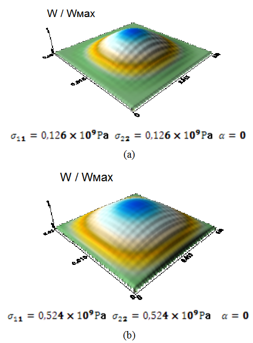 | Figure 6. Critical stresses and stability loss of orthotropic plate with rigidly clamped edges: (a) and hinged support edges; (b) the ratio h/a=h/b=1/100 |
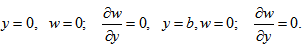
Critical loads and stability loss forms of orthotropic plate on an elastic foundation are shown in Figure 7. Hinged support or rigid clamping on all edges was used as boundary conditions. The ratio of the plate thickness to the length of the side along the x or y axis are equal to  . The elastic moduli Е1 = 380 GPa, Е2 = 190 GPa, G =80 GPa, Poisson's ratios ν1 = 0.30, ν2 = 0.15. Coefficient of subgrade k = 1 × 10¹⁰ N/м3, coefficients of linear thermal expansion α1 = 6 × 10⁻⁶ K-1, α2 = 9 × 10⁻⁶ K-1.
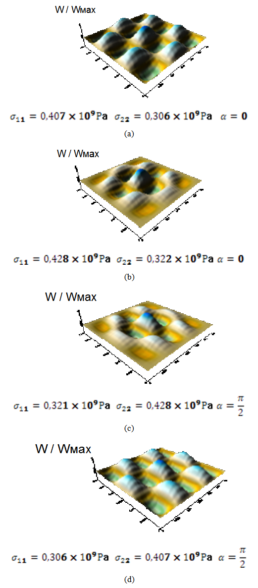 | Figure 7. Critical stresses and stability loss of orthotropic plate on an elastic foundation. a, d – hinged support, b, c – rigid clamping of the edges |
It is clear that the thermal impact causes stability loss of thermal barrier coating. Stability loss form looks like a chessboard, and along the axis of orthotropy with a high modulus of elasticity three half-waves were observed, while along the axis with a smaller module five half-waves can be placed. When rotating the axes of orthotropy by 90 the pattern of wave generation rotates accordingly under conditions of stability loss.Figure 8 shows the critical stresses and stability loss when the orthotropy О1X1Y1 axes are rotated relative to the global OXY axes by 45, coefficient of subgrade reaction k = 1 × 10¹⁰ N/m3. There is anisotropy; the matrix of elastic properties [D] is full. It is seen from Figure 8 that the pattern of wave generation is symmetrical regarding the orthotropy axes Х1О1Y1. 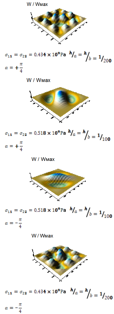 | Figure 8. Critical stress and stability loss forms of an orthotropic plate onto elastic foundation with rigid clamping edges. Orthotropy axis Х1О1Y1 are rotated relative to the global axes ОХY by the angle α |
When rotating the orthotropy axes by 90 the pattern of wave generation is rotated by 90, as well. If the ratio of plate thickness to the length of its side is equal to h/a = 0.01, then along the monoaxially orthotropy number of half-waves is equal to unit. Along the other axis the number of half-waves is equal to 3 If the ratio of plate thickness to the length of the side is equal to h/a = 1/200 then along one orthotropy axis the number of half-waves is 4, while along the other one – 3.
7. Stress - Strain State of an Anisotropic Plate after Stability Loss due to Thermal Impact
As the result of heating the size of orthotropic plate increases along the x and y axes by ΔL1 и ΔL2, and ΔL1 = α1ΔТL10, ΔL1 = α2ΔТL20. Bending of the plate (y = 0.015 m) is shown in Figure 9.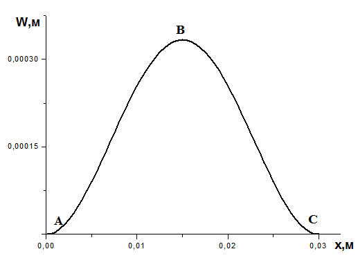 | Figure 9. Normal bending (deflection) W of the plate after stability loss due to a temperature effect. Boundary conditions – rigid clamping on all edges. The ratio h/a = h/b = 1/100 |
Normal bending of the plate W is calculated from the condition that the length of the curve ABC is L10+α1ΔТL10. Length of the curve ABC was calculated using the formula: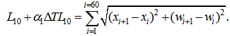 | (15) |
Parameters of the SSS of the orthotropic plate under bending W calculated on the basis of equation (12) are shown in Figure 10.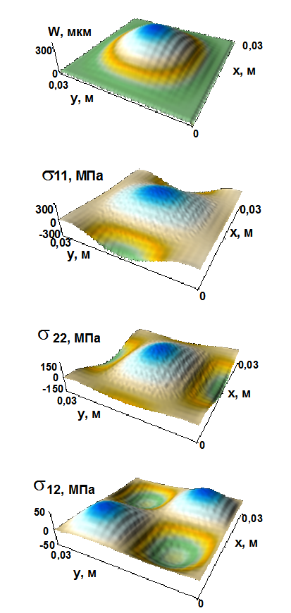 | Figure 10. Bending W of the orthotropic plate during heating and stability loss. Edges of a plate are clamped rigidly. The ratio h/a=h/b=1/100. Stresses along the x axis (σ11), stresses along the axis y (σ22), shear stresses σ12. Elastic base is absent |
Figure 11 shows the bending of a single cell of a "chessboard" to occur under stability loss of a plate. It is easily seen that the elastic foundation reduces the plate bending approximately by 2 times.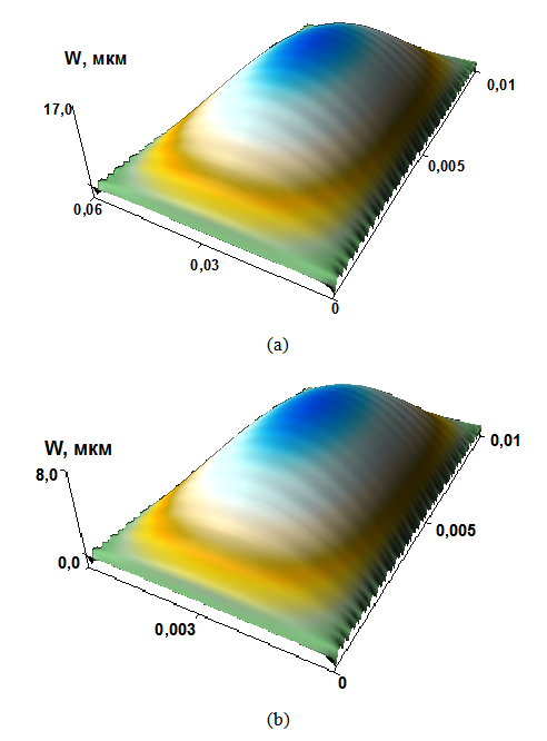 | Figure 11. Bending of the plates: without elastic foundation (a), coefficient of subgrade reaction K = 0; with elastic foundation (b), coefficient of subgrade reaction K = 1•1010 n/m3 |
The parameters of the stress-strain state of the plate on an elastic foundation after stability loss are presented in Figure 12. It may be noticed that the decrease in a film thickness (plate) and increase in rigidity (elastic modulus) of the substrate leads to growth in the number of half-waves at a fixed size of calculated area, and reduction of their amplitudes (Figure 12). Values of the stresses that arise due to the stability loss depend not only on the absolute value of the bending as the curvature of coating surface that occurs after stability loss, i.e. from the second derivatives of bending along the axes being parallel to the surface. In addition, stresses depend on the thickness of a plate. In this sense, the thickness affects the maximum stress values in two ways: on the one hand, under decrease in the thickness of the coating the enlargement in the number of waves under the stability loss leads to growth in curvatures, on the other hand – the couple stresses are reduced by reduction in the so-called cylindrical rigidity of the plate.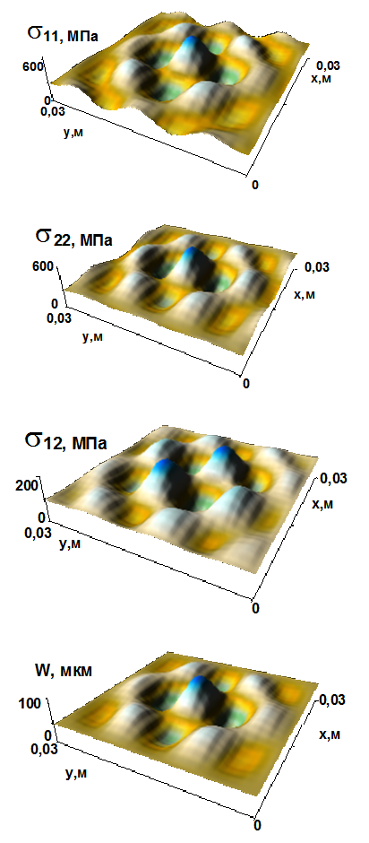 | Figure 12. Stresses along the x and y axes, the shear stresses in the plate on an elastic foundation under stability loss when heated. The bending of the plate after stability loss. The ratio h/a = h/b = 1/200. Coefficient of subgrade К = 1•1010 N/m3 |
This fact can be used for parametric studies and the determination of rational values of a coating thickness depending on the deformation, strength, and thermal characteristics of the coating and substrate materials.
8. Conclusions
Under the effect of thermal impact at the beginning when the substrate is still in its initial state (cold), there are significant compressive stresses in the coating, which may cause the stability loss as a thin-walled plate simulating the coating located on an elastic foundation (substrate).Extreme stress values are arranged in chessboard-like order at stability loss of the coating. If the physical and mechanical characteristics of the coating are anisotropic, changing the general pattern of the stability loss is changed compared to the isotropic coating. "Cells" of the chessboard are stretched along the axis which corresponds to a greater modulus.At the stability loss of the plate onto elastic foundation the number of waves on the coating surface increases with the stiffness of the elastic foundation and the reduction in the ratio of the plate thickness to its width and length. Calculations for a particular orthotropic coating had shown that for a square plate along the axis with a larger modulus of elasticity is a smaller number of half-waves rather than along the orthotropy axis with a lower modulus of elasticity. The stability loss of an anisotropic plate, whose axis is rotated relative to the global axes, intrusions and extrusions are arranged symmetrically with respect to the axes of orthotropy.
ACKNOWLEDGEMENTS
This study was carried out in the framework of the program of fundamental research for the State Academy of Sciences on 2013-2020.
References
| [1] | A.G. Evans, D.R. Mumm, J.W. Hutchinson, G.H. Meier, F.S. Pettit. Mechanisms controlling the durability of thermal barrier coatings // Progress in Materials Science. – 2001. – Vol. 46. – P. 505-553. |
| [2] | Koolloos, Martijn F.J. Behaviour of low porosity microcracked thermal barrier coatings under thermal loading / by Martijn F.J. Koolloos. – Eindhoven: Technische Universiteit Eindhoven, 2001. Proefschrift. – ISBN 90-386-2712-2. |
| [3] | Nissley D.M. Thermal Barrier Coating Life Modeling in Aircraft Gas Turbine Engines // Journal of Thermal Spray Technology. 1997. – V. 6. (I) March. – P. 91-98. |
| [4] | Liangde Xie, Xinqing Ma, Eric H. Jordan, Nitin P. Padture, Danny T. Xiao, Maurice Gell. Deposition mechanisms of thermal barrier coatings in the solution precursor plasma spray process // Surface and coating technology. – 2004. – V. 177-178. – Р. 103-107. |
| [5] | Amol D. Jadhav, Nitin P. Padture, Eric H. Jordan, Maurice Gell, Pilar Miranzo, Edwin R. Fuller Jr. Low-thermal-conductivity plasma-sprayed thermal barrier coatings with engineered microstructures // Acta Materialia. – 2006. – V. 54. – Р. 3343-3349. |
| [6] | Nemirovsky Yu.V., Mischenko А.V. Influence of materials and structure design for the plastic deformation and fracture of layered rod systems // Phys.mesomech. – 2004. –V. 7. – Sp.iss. Part. 1. – P. 180-183. |
| [7] | Grinyaev Yu.V., Panin V.Е. The calculation of the stress state in a polycrystal under elastic loading // Russian physics journal. – 1978. – No. 12. – P. 95-101. |
| [8] | Cherepanov G.P. On the theory of thermal stresses in a thin bonding layer // J. Appl. Phys. – 1995. –V. 78. – P6826-6832. |
| [9] | Cherepanov О.I. Numerical solution of some quasi-static problems of mesomechanics. Novosibirsk, Publishing house of SB RAS, – 2003. – 180 p., ISBN 5-7692-0595-4. |
| [10] | Panin V.E., Sergeev V.P., Panin А.V., Pochivalov Yu.I. Nanostructuring of surface layers and deposition of nanostructured coatings – an effective way of strengthening the modern structural and tool materials // J. Physics of metals and metallography. – 2007. – V. 104. – No. 6. – P. 650-660. |
| [11] | Panin L.Е., Panin V.E. The chessboard-like effect and mass transfer processes at the interface media of organic and inorganic nature. // Phys.mesomech. – 2007. – V. 10. – No. 6. – P. 5-20. |
| [12] | Zienkiewicz O.C., Morgan K. Finite Elements and Approximation. Dover Publications, 2006. – 328 p., ISBN 0486453014. |
| [13] | Segerlind L.J. Applied Finite Element Analysis (Second Edition). John Wiley and sons, 1984. – 427 p. |
| [14] | Bate K.-Yu. Finite elements methods. / Translated by V.P. Shidlovsky, ed. by L.I. Turchak. – М.: Phys.Mat.Lit. Nauka, 2010. – 1024 p. – ISBN 978-5-9221-1181-2. |
| [15] | Timoshenko S.P., Voynovsky-Kriger S. Plates and Shells: Translated – М.: Nauka, 1966. – 636 p. |
| [16] | Strength, stability, oscillations. / Book of References in 3 volumes. V. 3 - M.: Mashinostroenie, 1968. – 567 p. |
| [17] | Teters G.А., Richards R.B., Narusberg V.L. Optimization of shells made of layered composites. Riga: Zinatne, 1978. – 240с. |
| [18] | Zienkiewicz, O.C.; Taylor, R.L.; Zhu, J.Z. (2005). The Finite Element Method: Its Basis and Fundamentals (Sixth ed.). Butterworth-Heinemann. ISBN 0750663200. |
| [19] | Numerical methods in the theory of elasticity and the theory of shells. / Abovsky N.P., Andreev N.P., Deruga А.P., et.al. – Krasnoyarsk, 1986. – 384 p. |
| [20] | Lekhnitsky S.G. Anisotropic Plates. М.:ОGIZ, GOSTECHIZDAT, 1947. – 355 p. |
| [21] | Sosis P.М. Algorithmic language ALGOL 60 and its application in structural mechanics. – Kiev.: Budivelnik, 1965. – 172 p. |
 Abstract
 Reference
 Full-Text PDF
 Full-text HTML