Sungjin Lim1, Changduk Kong1, Huynbum Park2
1Dept. of Aerospace Engineering Chosun University #375 Seosuk-dong, Dong-gu, Kwangju , 501-759, Republic of Korea
2Dept. of Defense & Science Technology, Howon University 573-718, 64 Howondae 3gil, Impi, Gunsan, Rep. of Korea
Correspondence to: Changduk Kong, Dept. of Aerospace Engineering Chosun University #375 Seosuk-dong, Dong-gu, Kwangju , 501-759, Republic of Korea.
| Email: |  |
Copyright © 2012 Scientific & Academic Publishing. All Rights Reserved.
Abstract
Although the tower of the horizontal axis wind turbine system is a simple structure in comparison with the wind turbine rotor system, the production cost of the tower is about 20-25% of the whole wind turbine system cost. If a composite materials tower is used instead of the existing steel tower, the production cost can be reduced by using of low cost composite materials, simple manufacturing process, easy transportation and easy assembly. However studies on the composite materials towers are very few. In this study a specific structural design procedure for 2 MW class glass/polyester face sheets-sand/ polyester core sandwich composite wind turbine system towers is newly proposed through load case study, trade-off study, optimal structural design and structural analysis. Optimal tower design can minimize both weight and cost. In the structural design of the tower, three kinds of loads such as wind load, blades, nacelle and tower weight and blade aerodynamic drag load should be considered. Initial structural design is carried out using the netting rule and the rule of mixture. Then the structural safety and stability are confirmed using a commercial finite element code, MSC NASTRAN/PATRAN. It is confirmed that the final proposed tower meets the tower design requirements.
Keywords:
Composite Materials Wind Turbine Tower, Filament Winding, Optimal Design
Cite this paper: Sungjin Lim, Changduk Kong, Huynbum Park, A Study on Optimal Design of Filament Winding Composite Tower for 2 MW Class Horizontal Axis Wind Turbine Systems, International Journal of Composite Materials, Vol. 3 No. 1, 2013, pp. 15-23. doi: 10.5923/j.cmaterials.20130301.03.
1. Introduction
Mankind has used the wind energy at various types of fields for several thousands of years. Even though the wind power generation has a long history and economic renewal energy technology, its past technology was a bit lower effectiveness due to relying entirely on natural wind[1] .However recently the wind power generation system has been improved by the concentrated investments and research works on advanced technologies based on past experiences and technologies due to fossil fuel exhaustion, and become large scale wind turbines more than several MW class. Therefore both the turbine blade and the tower of the large scale wind turbine systems has become large scales[2]. In case of the blade the composite materials are widely used to reduce the weight, but the case of the tower the application examples of the composite materials are very few. Even though the tower is a simple structure relatively to other mechanical structures, development of a cost effective tower is important because the tower has 20-25% of the whole wind turbine system cost. The composite materials tower can reduce the production cost through use of low cost composite materials, simple manufacturing process, easy transportation and assembly relatively to the steel tower. According to literature survey results on existing towers, Tongguang Wang studied on a high resolution tower shadow model for downwind wind turbine[3], P. J. Murtagh studied on an along-wind response of a wind turbine tower with blade coupling subjected to rotationally sampled wind loading[4], Dimos J. Polyzois studied on the static and dynamic characteristics of multi-cell jointed GFRP wind turbine towers[5], Jane E. Lundberg studied on load and resistance factor design of composite columns[6]. In Korea, Hyeok-su Hong, studied on optimal design of a steel tower shell thickness of 2MW class wind turbine system through the numerical analysis of natural frequency, strength, fatigue and buckling depending on the shell thickness change and Dong-man Kim, studied on vibration characteristics of steel tower for a the large wind power turbine system considering wind loads and seismic loads. As mentioned the literature surveys on the composite materials towers are very few while studies on the steel tower are many. This work proposes a design procedure and optimal design results of the composite materials tower for the large scale wind turbine systems. Authors express thanks for Fiber Tech Co., Ltd.'s support that provided specimen experimental test data and manufacturing cost analysis data for this work.Figure 1 shows the proposed design procedure for this work.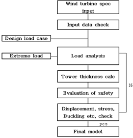 | Figere 1. Design procedure of wind turbine system tower |
2. Tower Design
In the tower design, firstly the design loads are defined through the load case analysis, secondly the filament winding method is adopted for manufacturing the tower, thirdly the optimal designs on both the thickness and the lay-up angles of each tower section is performed, and finally the designed tower structure's safety is evaluated using the FE analysis.
2.1. Structural Design Requirements
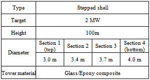
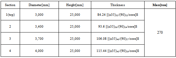
The tower is traditionally made from steel using steel considering the design requirements, the existing structural shapes, the manufacturing method, and then the designed steel tower is redesigned using composite material. Table 1. Tower system specification
 |
| |
|
Table 1 shows the tower system specification to be designed in this work. According to the literature survey of existing 2 MW class wind turbine systems, most towers have about 80m height[9]. However this work adopts the 100m height of tower due to considering the potentiality of application of 3-4 MW class wind turbine system tower as well as 2 MW.For easy transportation the tower is divided into 4 sections such as the top section of a constant diameter of 3m, the second section with a constant diameter of 3.4m, the third section with a constant diameter of 3.7m, the bottom section with a constant diameter of 4m. The joint parts between each sections have a truncated shape.
2.2. Load Case Analysis
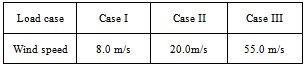
The wind load cases applied to the tower are classified in 3 cases such as Case 1 of the rated wind speed, Case 2 of the cut-off wind speed and Case 3 of the storm wind speed. In addition to the wind loading, the thrust load induced by the blade, the weights of nacelle, rotor blades and tower must be considered as design loads.Among them, generally the wind turbine blade has the design load at the cut-off wind speed condition with the gust. However, the tower has to endure the storm wind load as well as the cut-off wind load. Table 2 shows 3 load cases for designing the tower.Table 2. Load cases for tower design
 |
| |
|
Among 3 load cases, the load case 3 is considered as the design load case through calculating the loads applied on each tower section using the following experimental formula[2].In the storm load condition, the drag load, which can give the bending moment to the tower, occurs on the blade. This load can be estimated by the following experimental formula (1).  | (1) |
where  is the swept area produced by rotation of the blade. Pa, Fa are means to wind load and drag load.In addition to the blade's drag, the dead weights of nacelle including generator and gear box and blades are applied to the top of tower[3]. In this work, the weights of blades of 45 tons and nacelle of 180 tons including gear, shaft, generator, etc. which have been estimated in the previous study, are used.Figure 2 shows various loads applied on the tower. The wind load on the tower increases gradually along with the height. This load can be estimated using the following formula (2) defined by the regulation regarding Japanese construction standard.
 | (2) |
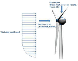 | Figure 2. Various loads applied on tower |
Where A is the projection area with a rectangular shape of tower, i.e., the wind drag area, and W is the wind pressure expressed by the formula (3).  | (3) |
Where  is the dynamic pressure
  ,
,  is the wind coefficient. For this work
  is 0.9, 0.84, 0.78, and 0.60 for section 1, 2, 3 and 4 of the tower, respectively.
 | (4) |
Where  is the coefficient defined by the regulation and 4.3, 4.0, 3.7 and 3.4 for section 1, 2, 3 and 4 of the tower, and
  is the tower design wind speed of 55m/s.Using the calculated loads above the bending moments can be obtained, then stresses, deflections and thicknesses of the tower using formula (5)[7].
  | (5) |
Where  and
and  are equivalent, bending and shear stresses, respectively, d is the tower diameter, I is the second area moment of inertia, J is the polar moment of inertia,
  and
and  are
are  and
and  directional forces on each section,
  and
and  are
are  and
and  directional moments on each section,
  is the tower projection area, and
  is the wind inclination angle. As shown at the formula (5), the equivalent stress is inversely proportioned to the thickness t of tower shell. Therefore the tower thickness, which satisfies the safety factor of 1 against the yield strength, can be obtained using the formula.
 | (6) |
where  is the equivalent stress obtained at the initial design,
  and
and  are the initially designed thickness and the modified thickness considering the safety.The formula (7) shows deformations of the tower.
 | (7) |
where  is the tower deformation due to the blade thrust load
  ,
,  is the tower height,
  is the tower deformation due to the distributed wind load
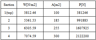
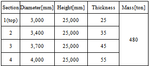
  .Table 3 shows the estimated wind loads on each tower section, and Table 4 shows the designed results of tower using steel. The tower weight is calculated using the commercial FE code, MSC.NASTRAN. The weight and the thickness of the designed tower are similar to the existing same class wind turbine tower[7]. Figure 3 shows the designed tower configuration using steel. The tower is divided into 4 sections such as the top section of a constant diameter of 3m, the second section with a constant diameter of 3.4m, the third section with a constant diameter of 3.7m, the bottom section with a constant diameter of 4m. The joint parts between sections have a truncated shape. The three truncated joint part sections have all the same heights of 2 m, and their upper and lower ends are met to the tower sections’ diameters. The details of the second joint part are shown at Figure 3.
Table 3. Estimated wind load on each tower section
 |
| |
|
Table 4. Tower design result using steel
 |
| |
|
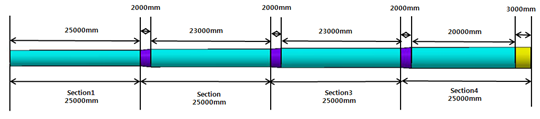 | Figure 3. Designed tower configuration using steel |
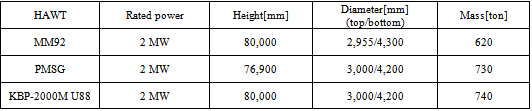
Table 5 shows technical data of the existing 2 MW class wind turbine towers[2],[3]. The reason why the weight of the designed 100m tower using steel is much lighter than that of the existing similar 80m class towers is caused by the use of its each section’s different thickness and no consideration of internal ladder and platform while the existing tapered tower has the same thickness at entire walls based on the thickest thickness at bottom wall.Table 5. Technical data of existing 2MW towers using steel
 |
| |
|
2.3. Redesign of the Steel Tower Using Composite Materials
The composite materials tower is manufactured by the filament winding method using glass/epoxy materials. The filament winding method is generally used to manufacture the shell type structures such as pressure vessel, pipe, etc.. This method is able not only to reduce manpower, manufacturing time and cost due to the manufacturing automation, but also to do mass production of large scale structures[10]. Moreover in order to lower than manufacturing cost, the glass/epoxy face sheets-sand/epoxy core sandwich type structure is adopted. Figure 4 shows the sectional view of the sandwich type structure of the tower.The joint ring parts between sections have a smooth truncated shape. Assembly between the joint ring part and the tower section is done by the flanges with bolts co-wound on the internal tower walls.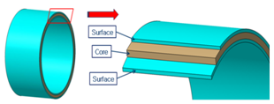 | Figure 4. Glass/epoxy face sheets-sand/epoxy core sandwich type structure of tower |
 | Figure 5. Conceptual design configuration of flange |
2.4. Trade-off Design for Design Optimization
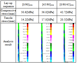
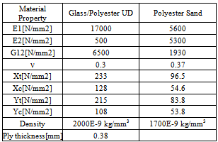
In this work the optimal winding pattern and thickness is determined considering proper safety factor, deflection at the tower top and weight through trade-off design. Table 7 shows the mechanical properties of used composite materials, and Table 8 shows the procedure how to determine the winding pattern through the stress analysis using FE. Among the various lay-up sequences,  the lay-up case has the lowest stress and displacement. Table 6 shows the stress analysis results of various lay-up sequences.
Table 6. Structural analysis results according to various lay-up sequences
 |
| |
|
Even though the best lay-up sequence case is  , the minimum possible winding by the manufacture Fiber Tec Co. is
  instead of
  . Therefore the practical winding angle becomes
  instead of
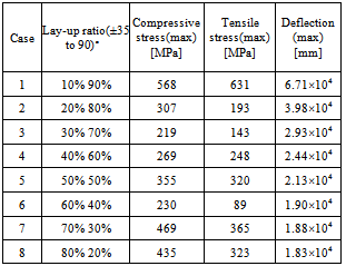
  . Table 8 shows maximum compressive and tensile stresses and tower top deflections depending on the lay-up ratio of
  . The Case 3 has the lowest compressive stress, while it has the higher tensile stress and deflection than the Case 6. Therefore the Case 6 is determined as a final best lay-up sequence. Figure 6 shows the trend of maximum compressive and tensile stresses and tower top deflections depending on the lay-up ratio of
  .
. Table 7. Mechanical properties of used materials
 |
| |
|
Table 8. Structural analysis results depending on various lay-up ratio
 |
| |
|
 | Figure 6. Max stresses (tensile and compressive) and tower top deflection versus lay-up ratio (w/o core) |
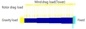 | Figure 7. Loading and geometrical boundary conditions of tower for FE analysis |
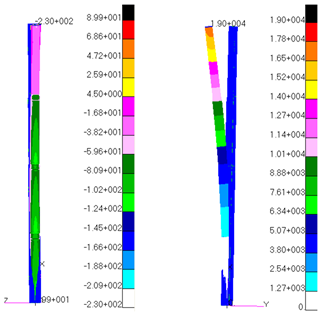 | Figure 8. stress analysis results including stress distribution and deformed shape of the tower at Case 6 lay-up sequence |
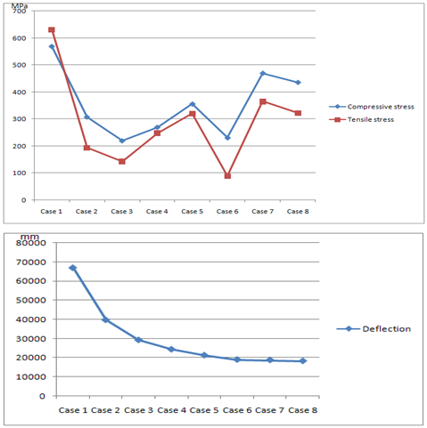
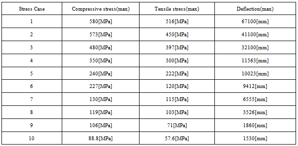
Figure 7 and 8 show the loading and geometrical boundary conditions and the stress analysis results including stress distribution and deformed shape of the tower, respectively. According to the stress analysis results of Fig. 8, the tower top deflection is very large. Therefore by adapting the sandwich structure with sand/epoxy core and increasing its thickness, the top deflection is reduced and the structural stability enhanced.The thickness optimization is performed by gradual increasing through checking both the structural stability and the deflection. The lay-up thickness allocation having the symmetric[±35],[90] and[core] sequence at each section has 30%, 20% and 50%, respectively. Table 9 shows 10 design cases for various thickness at 4 tower sections, Table 10 and Fig. 9 shows the stress analysis results including maximum stresses and top deflection of 10 design cases. Among all 10 design cases, the case 10 is selected as a final design result that satisfies both the structural safety and stability and the top deflection. The final design results are shown at Table 11.The structural stability means the structural buckling safety due to compressive loads occurred by the tower bending moment or the tower dead weight including weights of blades, nacelles and power generation system.Table 9. Thickness design cases of 4 sections
 |
| |
|
Table 10. Stress analysis results including maximum stresses and top deflection of 10 design cases
 |
| |
|
Table 11. Design result of composite tower using sandwich structure
 |
| |
|
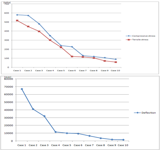 | Figure 9. Max stresses (tensile and compressive) and top deflection versus thickness(w core) |
The weight of the final proposed 100m height composite tower is 270ton. It is much lighter than the existing 80m height steel tower having 450~700ton[10]. Figure 10 shows spanwise stress distribution on outer skin and deformation of the proposed composite tower. 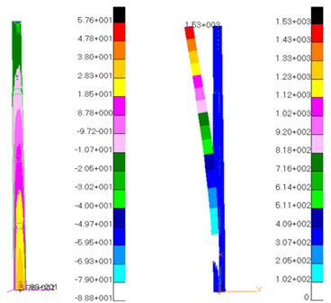 | Figure 10. Spanwise stress distribution on outer skin and deformation of proposed composite tower |
Figure 11 shows the buckling mode shapes and the buckling load factors, and Fig. 12 the Campbell diagram to check the resonance possibility at the constant operating rotational speed of 20rpm. 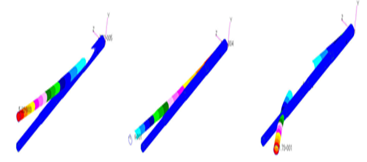 | Figure 11. Tower buckling mode shapes and its load factors |
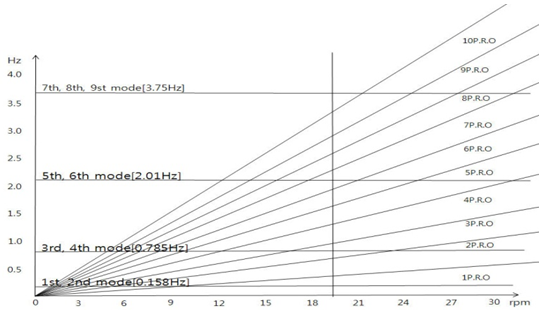 | Figure 12. Campbell diagram of proposed tower |
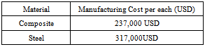
In order to investigate the cost effectiveness of the proposed composite tower, its manufacturing cost is compared with the existing steel tower's manufacturing cost. Table 12 shows the comparison result between the manufacturing costs of the proposed composite tower and the existing steel tower. This manufacturing cost data are provided by a wind turbine system tower manufacturing company, FIBERTEC Co. Ltd. The cost contains materials price, labor cost and other costs. Table 12. Comparison of manufacturing cost between composite and steel towers (provided by FIBRETECH. Co. ltd.)
 |
| |
|
3. Conclusions
This work proposes a composite materials tower for 2 MW class horizontal wind turbine system using the filament winding manufacturing process. The tower is designed by the following methods;Firstly, the glass/epoxy face sheets-sand/epoxy core sandwich type structure is adopted considering the manufacturing cost, and the structure is optimized through minimizing the weight together with structural stability and safety.Secondly, the base design winding angle has the minimum manufacturing capable angle of ±35° instead of the theoretical optimal angle of 0° having the best strength and the combination angle of 90° having the secondary strength. The thicknesses of each tower section are optimized through reducing stress, deformation and weight by the thickness variation.Thirdly, it is confirmed that the final proposed composite materials tower is safe through investigation of stresses, deformations, structural stability and natural frequencies, and much lighter than the existing same class steel towers.Finally, the proposed tower will be validated by the structural tests of the prototypes to be manufactured.
ACKNOWLEDGMENTS
Authors express full acknowledgment for ASME’s publication permission of this material as original publisher ASME Turbo Expo 2013, Paper Number GT2013-94124 in International Journal of Composite Materials.
References
| [1] | C. Kong, J. Bang, Y. Sugiyama, "Structural investigation of composite wind turbine blade considering various load case and fatigue life" Journal of Energy, Vol.30, 2005, pp. 2101-2114. |
| [2] | Desire Le Gourieres "Wind power plants theory and design" Pergamon Press, UK, 1998. |
| [3] | Tongguang Wang. "A high resolution tower shadow model for downwind wind turbine", Journal of Wind Engineering and Industrial Aerodynamics 89, 2001, pp. 873-892 |
| [4] | P.J.Murtagh, "Along-wind response of a wind turbine tower with blade coupling subjected to rotationally sampled wind loading", Engineering Structures 27, 2005, pp. 1209-1219 |
| [5] | Dimos J. Polyzois. "Static and dunamic characteristics of multi-cell jointed GFRP wind turbine towers", Composite Structures, 2009, pp. 34-42 |
| [6] | Jane E.Lundberg, Theodore V.Galambos "Load and resistance factor design of composite columns" Structural Safety, Vol.18, No.2/3, pp. 169-177. |
| [7] | Hyeoksoo Hong. “Research for 2MW Wind Turbine Tower Shell Design Optimization", The Korean Society For New and Renewable Energy, 12.Vol.2, No.4 2006, pp. 19-26 |
| [8] | Kim Dongman. " Vibration Analysis of MW Class Wind Turbine Tower Considering Earthquake Base Excitation", Korea Wind Energy Association(KWEA), 2009 |
| [9] | Spera. D.A "Wind turbine technology", ASME Press, 1994, pp.139-194 |
| [10] | Hani M. Negm. " Structural design optimization of wind turbine towers", Computers and Structures 74, 2000, pp. 649-666 |
 Abstract
 Reference
 Full-Text PDF
 Full-text HTML