A. Okasha El-Nady 1, Hani M. Negm 2
1Mechatronics Dept., Faculty of Engineering, October 6 University
2Aerospace Eng. Dept., Cairo University
Correspondence to: A. Okasha El-Nady , Mechatronics Dept., Faculty of Engineering, October 6 University.
| Email: |  |
Copyright © 2012 Scientific & Academic Publishing. All Rights Reserved.
Abstract
In this work a simple technique for the analysis of arbitrarily laminated composite beams is proposed using a higher-order shear deformation theory. The governing equations are derived by minimizing the total potential energy of arbitrarily laminated beams undergoing axial and transverse shear strains under laterally distributed load. The displacement and rotation of the beam center line are expanded in Chebyshev series. Using a standard procedure the governing equations are cast in matrix form, which is easily handled by electronic computers. The displacements and stresses of several laminated beams are calculated and compared with published results.
Keywords:
Higher-Order Theory, Composite Beams, Chebeyshev Series
Cite this paper:
A. Okasha El-Nady , Hani M. Negm , "Analysis of Arbitrarily Laminated Composite Beams Using Chebyshev Series", International Journal of Composite Materials, Vol. 2 No. 5, 2012, pp. 72-78. doi: 10.5923/j.cmaterials.20120205.02.
1. Introduction
Beam structures are among the most important structures in aerospace applications. Multilayered composites have gained wide application in aerospace industry due to their high strength-to-weight and stiffness-to-weight ratios. Conventional analysis of beams uses the classical beam theory based on Bernoulli-Euler hypotheses[1], and hence, neglects shear deformation. This theory adequately describes the behavior of slender beams, but is less adequate for thick beams in which shear deformations are important.Timoshenko[2] extended the classical theory to produce a first-order shear deformation theory. This is an improvement on the classical theory which reduces to it as the beam becomes thinner. A defect of Timoshenko theory is that the assumed displacement approximation violateas the "no-shear" boundary condition at the top and bottom of the beam. Levinson[3] introduced a higher-order theory to correct the drawback of Timoshenko's theory. It is based on a cubic in-pane displacement approximation that satisfies the no-shear condition.Bickford[4] noted that the derivation used by Levison was variationally inconsistent, and derived a corrected version from Hamilton's principle. In addition, he presented some representative solutions for simple beams. Heyligher and Reddy[5] presented a finite element solution for Bickford’s theory using polynomial shape functions. J. Petrolito[6] presented a finite element solution for isotropic beams based on a higher-order shear deformation theory. Solutions of the governing differential equations are derived and used as element shape functions.For laminated beams, the classical lamination theory[7, 8, 9] is adequate to predict the global response of laminates with relatively small thickness. Because of the low shear to in-plane stiffness ratio, the important role of transverse shear deformation, which is not contained in the classical lamination theory, cannot be neglected. S. Gopalakrishnan et al[10] derived a refined 2-node, 4-DOF composite beam element based on a higher-order shear deformation theory in asymmetrically stacked laminates. V. G. Mokos and E. J. Saountzakis[11] developed a boundary element method for the solution of the general transverse shear loading of composite beams of arbitrary constant cross section. Exact solution for the bending of thin and thick cross-ply laminated beams was presented by Khedir and Reddy[12 and 13] using the state space concept. Exact solution for arbirarily-laminated beams based on a higher-order shear deformation theory was presented by A. Okasha[14]. The exact analytical solution is restricted to simple geometry and loading. For general analysis, it is preferable to use a numerical approach. In practice, some care needs to be taken with numerical solutions to avoid difficulties, such as locking with increasing beam aspect ratio. This is of major concern when using higher order theories for beams and plates[6, 10]. To avoid these difficulties of exact and numerical solutions of differential equations based on the higher-order theory, approximate analytical solution in the form of Chebyshev series is proposed.In the present work the analysis of arbitrarily laminated composite beams is presented based on a higher-order shear deformation theory using Chebyshev series. The governing equations are derived by minimizing the total potential energy of arbitrarily laminated beams undergoing axial and transverse shear strains under laterally distributed load. The displacement of the beam w and rotation θ are expanded in Chebyshev series. Using a standard procedure the governing equations are cast in matrix form, which is easily handled by electronic computers. Using this method it is possible to analyze beam structures with small aspect ratios. The displacements and stresses of several laminated beams are calculated and compared with published results. The effect of ply stacking in symmetric and asymmetric laminated beams with different boundary conditions and aspect ratios is investigated.
2. Mathematical Formulation
2.1. Kinematic Relations
Assuming that the beam is subjected to lateral load only as shown in Fig. (1); the deformation of the beam is described by two displacements, U and W, and a rotation, θ. These displacements are assumed to be of the form[6, 10]: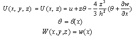 | (1) |
where h is the depth of the beam.
2.2. Strain-Displacement Relations
The beam is considered as a wide beam. So, the only non-zero strains are[6]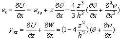 | (2) |
2.3. Stress-Strain Relations
The laminate stresses are | (3) |
where  and
and  are given in Appendix A.
3. Governing Equations
3.1. Differential Equations
Minimizing the total potential energy of the beam can lead to the governing equations of static analysis of the beam. In the present case, the total potential energy,  is
is  | (4) |
where q is the applied transverse load per unit length of the beam, b is the width and L is the length of the beam. Taking into consideration that variation in the potential energy is due to variation in the displacements and strains, then the first variation of the potential energy,  , can be written as:
 | (5) |
Substituting equations (1)-(3) into equation (5) and integrating over the width and depth of the beam, equation (5) takes the form | (6) |
where EA is the axial stiffness, B1 and B2 are the cross-coupling terms due to axial-flexural deformation of the composite laminated beam.  are the bending stiffnesses and
  is the shear stiffness of the laminated composite beam, and all are defined in Appendix A. Integration by parts and equating to zero gives the equilibrium equations of arbitrarily laminated beam
 | (7) |
where a prime denotes  . The procedure also leads to the definition of the generalized forces used in expressing the beam boundary conditions
 | (8) |
The force  can be interpreted as a generalized shear force, while
  and
and  are generalized moments. Also, the force N can be interpreted as a generalized axial force. With these definitions, the appropriate boundary conditions for the beam are as follows:1) either
  or
or  is specified;2) either
  or
or  is specified;3) either
  or
or  is specified;4) either
  or
or  is specified;For most practical problems the properties of the beam are constant along the length of the beam. In this case, equations (7) and (8) reduce to
 | (9) |
and | (10) |
Therefore, the higher-order beam theory is represented by a system of ordinary differential equations of order six.
3.2. Boundary Conditions
Fixed end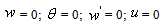 | (11) |
Hinged endat ξ = 0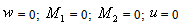 | (12) |
Roller endat ξ = 1 | (13) |
Free end | (14) |
4. Solution of the Governing Equations
The exact analytical solution is restricted to simple geometry and loading. The exact solution of equation (9) is limited as it contains sinh and cosh terms, which tend to infinity as the length to the depth ratio of the beam increases. For general analysis, it is preferable to use a numerical approach. In practice, some care needs to be taken with numerical solutions to avoid difficulties, such as locking with increasing beam aspect ratio. This is of major concern when using higher order theories, not only for beams but also for plates[6, 10]. To avoid these difficulties of exact and numerical solutions of differential equations based on the higher-order theory, an approximate analytical solution in the form of Chebyshev series is proposed.Using the nondimensional coordinate ξ=x/L and expanding w(ξ), θ(ξ) and u(ξ) in (N+1)-term Chebyshev series we have a total of 3N+3 unknown coefficients. Using matrix formulation for the functions and function derivatives and applying the rule of matrix multiplication as explained in reference[15], equations (9) can be written as a system of algebraic equations in the following matrix form: | (15a) |
 | (15b) |
 | (15c) |
where[A01],[A02],[A03] and[A04] are matrices of order N x N+1, N-1 x N+1, N-2 x N+1 and N-3 x N+1 respectively. They are derived in reference[15] and are given in Appendix B. The highest derivative expressed by equation (15a) is of order 4, so the number of algebraic equations in it is N-3. On the other hand, the highest derivative expressed by equations (15b) and (15c) are of order 3, so the number of algebraic equations is N-2 in each. Hence, the total number of algebraic equations is 3N-7 in 3N+3 unknown wi, θi and ui coefficients. Hence, the total number of algebraic equations is 3N-7 along with 8 boundary conditions at ξ=0 and ξ=1. This leads to 3N+1 equations in 3N+3 unknowns, which have an infinite number of solutions. To overcome this difficulty θ(ξ) and u(ξ) are expanded in N-term Chebyshev series, while w(ξ) is expanded in an N+1-term Chebyshev series. This way, the number of unknown Chebeyshev coefficients is reduced to 3N+1, and the system of equations (15) along with the boundary conditions can be easily solvedIt is important to note that all matrices in each of equations (15) take the order of the matrix corresponding to the highest derivative. That is, in (15a) all matrices are of order (N-3 x N+1), while all matrices in (15b) and (15c) are of order (N-2 x N).
5. Results and Discussions
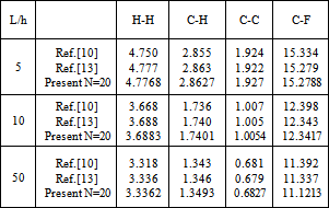
To study convergence of Chebyshev solution, the nondimensional deflection of symmetric and asymmetric cross-ply laminated beams with different boundary conditions are calculated and compared in Table (1) and Table (2) with the published results[10, 13]. The beams have the following dimensionless orthotropic material properties E11/E22 = 25; G12 = 0.5E22; G23 = 0.2E22; ν12 = 0.25, and the deflections are non-dimensionalized as w*=  .
.Table 1. Non-dimensional central displacement,
 of symmetric[0/90] cross-ply laminated beams with different boundary conditions of symmetric[0/90] cross-ply laminated beams with different boundary conditions
 |
| |
|
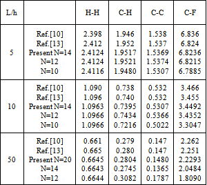
Table 2. Non-dimensional central displacement,
 of symmetric[0/90/0] cross-ply laminated beams with different boundary conditions of symmetric[0/90/0] cross-ply laminated beams with different boundary conditions
 |
| |
|
It is clear from the results that Chebyshev solution converges to the exact solution given in reference[13], and that 14:20 terms are sufficient to get good results. The proposed procedure is then used to study the effect of ply stacking of symmetric and asymmetric laminated beams with different boundary conditions and aspect ratio, L/h=5, on the central displacement response. The results are shown in Figs. 2-9. It is clear from the figures that symmetric laminates exhibit lower transverse deflections than asymmetric ones. The axial-flexural coupling doesn't exist in the symmetric laminates, and its effect increases as the degree of asymmetry increases to reach the highest value in cross-ply laminates. Also, the axial-flexural coupling, which may cause delamination, varies along the beam span according to the boundary conditions. Delamination starts at the end which is free to move in the axial direction irrespective the boundary conditions at the other end. In case of fixed-fixed beam, delamination starts nearly at the quarter-span from the two ends. | Figure 1. Beam Geometry |
 | Figure 2. Axial Variation of non-dimensional displacements of symmetric and asymmetric cross ply laminated H-H beams (L/h=5) |
 | Figure 3. Variation of non-dimensional mid-span displacements with the orientation of symmetric and asymmetric laminated H-H beams (L/h=5) |
 | Figure 4. Axial Variation of non-dimensional displacements of symmetric and asymmetric cross ply laminated C-H beams (L/h=5) |
 | Figure 5. Variations of non-dimensional mid-span transverse displacement and full-span axial displacement with the orientation of symmetric and asymmetric laminated C-H beams (L/h=5) |
 | Figure 6. Axial Variation of non-dimensional displacements of symmetric and asymmetric cross ply laminated C-C beams (L/h=5) |
 | Figure 7. Variation of non-dimensional mid-span transverse displacement and quarter-span axial displacement with the orientation of symmetric and asymmetric laminated C-C beams (L/h=5) |
 | Figure 8. Axial Variation of non-dimensional displacements of C-F beams (L/h=5) |
 | Figure 9. Variation of non-dimensional mid-span displacements with the orientation of symmetric and asymmetric cross ply laminated C-F beams (L/h=5) |
6. Conclusions
An approximate analytical method using Chebyshev series is proposed for the analysis of arbitrarily laminated composite beams based on the higher order shear deformation theory. The method is powerful in the analysis of short beams and quickly converges to the exact solution. The method can be easily applied to different loading and boundary conditions.
APPENDIX A: Bending and Torsion Stiffnesses of Laminated Beam According to the Higher-order Theory
The stress-strain constants appearing in equation (3) are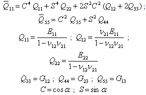
 is the angle between the fiber axis and the global laminate axis.The bending stiffnesses appearing in equation (6) are
 | (A1) |
where | (A2) |
 | (A3) |
The shear stiffness  appearing in equation (6) is
 | (A4) |
where | (A5) |
 | (A6) |
The axial stiffness  appearing in equation (6) are
 | (A7) |
 | (A8) |
The cross coupling terms B1 and B2 appearing in equation (6) is | (A9) |
 | (A10) |
APPENDIX B: Matrix Formulation for Functions and Function Derivatives
Any continuous function f(ξ) in the interval 0 ≤ ξ ≤ 1 and its derivatives can be written in Chebyshev series as follows: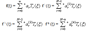 | (B1) |
The matrices[A01] to[A04] relate the 1st, 2nd, 3rd and 4th derivative coefficients of a function to the original function coefficients. The first-order-derivative coefficients { } as defined in Ref.[15] can be written in terms of the original function coefficients {ai} using matrix notation as follows:
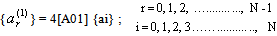 | (B2) |
where[A01] is of order N x N+1. It is composed of an N x N matrix designated as[A] matrix and an N x 1 column with zero entries at the left of matrix[A]Matrix[A] is an upper triangular matrix. Its elements aij are defined as: The form of[A] and[A01] for N=5 for example is:
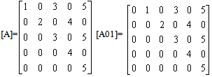 The matrices[A02],[A03],[A04] and[A0n] which relate the 2nd, 3rd, 4th and nth derivative coefficients to the original function coefficients are obtained as follows:where,n … the order of derivative [A]1-n, 1-n … matrix[A] after deleting the last (n-1) rows and (n-1) columns.-1[ ] … matrix[ ] after deleting the first row.
Nomenclature
E11, E22 Young's moduli in 1 and 2 directions respectively.G12, G13, G23 Shear moduli in 1-2, 1-3 and 2-3 planes respectively.L, b, h Beam length, width and height respectively.U, W Axial and transverse global-beam displacements respectively.u, w Axial and transverse displacements along the beam reference plane.q Lateral distributed load per unit length Angle between the fiber axis and the laminate axis.θ Beam rotation about y-axisν12 Poisson ratio for transverse strain in the 2-direction when stressed in the 1-direction.σ1, σ2, τ12 In-plane stresses in local lamina coordinates.
References
| [1] | Z. M. Elias, Theory and Methods of Structural Analysis. Wiley-Interscience, New York (1986). |
| [2] | S. P. Timoshenko, On the correction for shear of the differential equation for transverse vibrations of prismatic bars, Phil. Mag. Vol. 41, pp. 744-746, (1951). |
| [3] | M. Levinson, A new rectangular beam theory, J. Sound Vibr. Vol. 74, pp. 81-87, (1981). |
| [4] | W. B. Bickford, A consistent higher order beam theory, Devl. Theor. Appl. Mech., vol. 11. 137-150, (1982). |
| [5] | P. R. Heyliger and J. N. Reddy, A higher order beam finite element for bending and vibration problems, J. Sound Vib. Vol. 126, pp. 309-326, (1988). |
| [6] | J. Petrolito, Stiffness analysis of beams using a higher-order theory, Computers & Structures vol. 55, pp. 33-39, (1995). |
| [7] | Ever J. Barbero, Introduction to Composite Materials Design, Taylor Frances, Philadelphia, PA19106, USA, (1999). |
| [8] | Lee R. Calcote, The Analysis of Laminated Composite Structures, VAN Reinhold Company, (1969). |
| [9] | Stephen R. Swanson, Introduction to Design and Analysis with Advanced Composite Materials, Prentice Hall, Inc., (1997). |
| [10] | M. V. V. S. Murthy, D. Roy Mahapatra, K. Badarinarayana and S. Gopalakrishnan, A refined higher order finite element for asymmetric composite beams, Composite Structures, vol. 67, issue 1, pp. 27-35, January (2005). |
| [11] | V.G. Mokos and E.J. Sapountzakis, A BEM solution to transverse shear loading of composite beams, International Journal of Solids and Structures, vol. 42, issue 11-12, pp. 3261-3287, January (2005). |
| [12] | A. A. Khedir and J. N. Reddy, Free vibration of cross-ply laminated beams with arbitrary boundary conditions. Int. J. Eng. Sci. vol. 32, 12, pp. 1971-1980, (1994). |
| [13] | A. A. Khedir and J. N. Reddy, An exact solution for the bending of thin and thick cross-ply laminated beams. Composite Structures, vol. 37, pp. 195-203, (1997). |
| [14] | A. Okasha, Exact solution of arbitrarily laminated composite beams using a higher-order theory. Eleventh International Conference on Aerospace Science and Aviation Technology, Military Technical College, Cairo, 2005. |
| [15] | A. Okasha and H. M. Negm, Matrix formulation of Chebyshev solution to shell problems. Tenth International Conference on Aerospace Science and Aviation Technology, Military Technical College, Cairo, 2003. |
 Abstract
 Reference
 Full-Text PDF
 Full-Text HTML