Aayush Bansal , Ajeya Gupta , Mohit Pundir , Vibhas Mishra , V.K. Srivastava
Department of Mechanical Engineering, Indian Institute of Technology, BHU, Varanasi, 221005, India
Correspondence to: V.K. Srivastava , Department of Mechanical Engineering, Indian Institute of Technology, BHU, Varanasi, 221005, India.
| Email: |  |
Copyright © 2012 Scientific & Academic Publishing. All Rights Reserved.
Abstract
Fiber reinforced polymer composites (FRPs) are being increasingly used for a wide range of engineering applications owing to their high specific strength and stiffness. However, there through-the-thickness performance lacks some of the most demanding physical and mechanical property requirements for structural applications, such as aerospace vehicles and military components. Charpy impact test was done on end notched specimens of cross-plied glass fiber reinforced epoxy resin (GFRP) composites. Alumina and flyash particles were added in the epoxy resin with the weight ratio of 2.5%. The effect of notched length and fillers on dynamic performance of GFRP composite was obtained. Finally, SEM images were used to explain the changes in mechanical properties.
Keywords:
Glass Fiber, Epoxy Resin, Alumina, Flyash, Charpy Impact Energy, Dynamic Fracture Toughness, Scanning Electron Microscope
Cite this paper:
Aayush Bansal , Ajeya Gupta , Mohit Pundir , Vibhas Mishra , V.K. Srivastava , "Dynamic Performance of Particles Loaded Cross-Plied GFRP Composite", International Journal of Composite Materials, Vol. 2 No. 5, 2012, pp. 67-71. doi: 10.5923/j.cmaterials.20120205.01.
1. Introduction
Fiber reinforced polymer composites possess high specific moduli and specific strengths and are widely used in many structural applications including aerospace, sporting goods, automobile, civil and marine structures. While the inplane and fiber dominant properties make these composites useful in these applications, their through-the-thickness properties are limited by the relatively poor properties of the matrix resin and the weak fiber-matrix interfacial bond. In order for FRPs to offer better choice for aerospace and military components over monolithic metallic structures possessing no delamination problems, significant improvements in the through-the-thickness properties are necessary.It is well known that composite structures in the form of laminates are extremely susceptible to crack initiation and propagation along the laminar interfaces in various failure modes. In fact, delamination is one of the most prevalent life-limiting crack growth modes in laminate composites as delamination may cause severe reductions in in-plane strength and stiffness, leading to catastrophic failure of the whole structure[1]. Delamination may be introduced by external loading as in static bending, compression or tension, in cyclic fatigue or by impacts of low-to-high energies, during manufacturing or in service.Impact loading during service is a common phenomenon for aerospace composite structures. There are situations like tool drops, runway debris, bird strikes, hailstorms and ballistic strikes, which induce considerable damage to the composite. In order to produce an impact resistant structure, it is important to understand the dynamics of the impact event and thus to predict the extent of the induced damage and estimate the residual properties so that the composites are designed with improved structural integrity and mechanical performance after impact[2-3]. Many useful techniques have been successfully devised to improve the delamination resistance in the past three decades[4-7]. In addition to the resistance to interlaminar fracture and impact damage, FRPs for advanced aerospace structures often require the most demanding multi-functional properties. The introduction of nanotechnology in the field of composite materials with nanoscale fillers, such as carbon nanotubes (CNTs) and carbon nanofibers (CNFs), has offered new opportunities to improve these mechanical andmultifunctional properties of FRPs[8]. In light of their excellent Young’s modulus and strength, extremely high aspect ratio, large surface area, and excellent thermal and electrical properties, these nanofillers can be incorporated into the FRPs to modify the properties of polymer matrix[9-11].This paper aims to provide an overview of the enhancement of charpy impact energy and dynamic charpy impact toughness properties of GFRPs, especially the impact and delamination resistance, arising from the incorporation of alumina and flyash fillers in the composites.
2. Experimentation
2.1. Materials and Sample Preparation
The composites were made from commercially available 90/0° Cross-ply E-Glass Fibre. The matrix material was Epoxy resin, which is procured from Resinova Chemie Ltd., Kanpur, India. The epoxy resin was contained Araldite (LY-554) and hardener (HY-951). They were mixed properly with the weight ratio 10:1.The fly-ash was obtained from Obra Thermal Power Station, Mirzapur, U.P. India. The fly ash powder is a mixture of different chemical constituents such as Silica (56.04%), Alumina (24.90%), FeO/Fe2O3 (1.26%), CaO (2.2%), MgO (0.94%) and unburned coal etc. The physical properties of fly-ash include density (3.385 g/cc), porosity (0.38) and particle diameter (63-105 µm). The alumina powder was of Sasol, Germany. The particle size was in the range of 15-60 µm. The mixture has an alumina percentage of 72-77%. The surface area is 170-250 m2/g. The crystalline size of alumina powder is 4.5-10 nm.Hand lay-up method was used for the fabrication of composite specimens. Fourteen layers of cross-plied E-glass-fiber sheets were composed with the epoxy resin to make a single large composite plate. The resin and hardener were taken in the ratio of 10:1 by weight. A constant load of 20 kg was placed on the top of layer to control the weight ratio of fiber and epoxy resin, because excess amount of epoxy resin was squeezed out from the inside the fiber layers. The specimen was left for curing at ambient conditions under the influence off applied weights for 24 hours. Later on post curing was done in furnace at 50-60℃ for 1 hr. Similarly, specimen 2 and 3 was fabricated with the introduction fillers in epoxy resin before the addition of hardener.Three different composites were made. Initially, plain GFRP without filler material was prepared. Later, it was blended with 2.5% Fly-ash by weight of epoxy and with 2.5% Alumina by weight of epoxy respectively (which is referred as specimen 1, 2 and 3 respectively).The weight fraction of the glass in the composite was controlled through the application of weights during curing. However, burn-off method was used to measure the exact weight ratio of fiber and epoxy resin. First, composite specimen (10x10 mm) was weighted and placed in crucible. The crucible with composite template was kept in furnace at 250OC for 5 hr. The epoxy resin was burn out and then the weight of fiber was measured. Finally, weight fraction of glass fiber and epoxy resin was obtained as 0.541 in specimen-1, 0.5327 in specimen-2 and 0.4663 in specimen-3 respectively.The composite plates obtained above were then cut into ENF specimen, which dimension is shown in Figure 1. For each specimen (i.e. 1, 2, and 3) three different notch lengths were made as shown in the Table 1. The initial notch length was introduced by placing thick plastic sheet between glass ply 7 and 8 during the Hand-Layup procedure. The notch was later opened through a sharp knife-edge and mallet.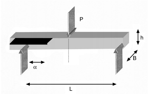 | Figure 1. Schematic diagram of End-notched specimen |
| Table 1. Specimen Dimensions |
| | Specimen No. | Length L (mm) | Breadth B (mm) | Height h (mm) | Initial Crack Length α (mm) | | 1 | 124 | 10.20 | 6 | 17.7, 25.4, 43.1 | | 2 | 124 | 10.40 | 6.5 | 25.4, 43.1, 50.8 | | 3 | 124 | 10.30 | 7.2 | 25.4, 43.1, 50.8 |
|
|
2.2. Charpy Impact Test
The impact test was performed with instrumented charpy equipment (Model; Resil Impactor-50, CEAST, S.p.A., Italy), as shown in Fig. 2. The impact-hammer and vice lever with specimen adapter used were according to Charpy impact test. The impact length and impact velocity were 0.327m and 3.46m/s.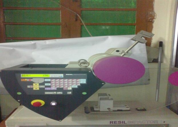 | Figure 2. Photograph of Resil charpy impact test |
Charpy test was performed on ten ENF samples of each class of composites (type-1, 2, and 3). The average results were reported to obtain the impact energy and toughness of each sample. The impact energy required for each specimen was indicated by the machine and was recorded. The fractured specimens are presented in Fig. 3.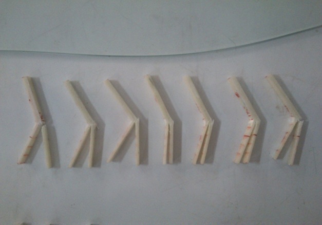 | Figure 3. Fractured specimens under impact test |
2.3. Scanning Electron Microscopy Test
The fractography study was used with the help of scanning electron microscopy (SEM), Philips-XL-20, which is available in the Dept. of Physics, BHU. For SEMobservation on the fractured specimens, the black soot-like material was directly mounted to the sample holder with silver glue which is electrically conductive.
3. Results and Discussion
3.1. Variation of Impact Energy
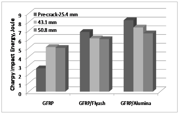 | Figure 4. Variation of charpy impact energy with specimen |
Fig. 4 shows the variation of impact energy with change in the initial crack length of different specimen made by third phase in the addition of to cross-plied E-glass fiberreinforced epoxy resin composites. The results clearly indicate that the variation in impact energy with the initial crack lengths 25.4, 43.1 and 50.8 mm respectively. Since, the specimen goes under delamination under the dynamic impact loading condition (Charpy impact test) therefore the specimen with lowest initial crack length would absorbed more energy for delamination, which is explained by the graph (as delamination occurred till the point of impact), i.e. specimen with lowest initial crack length 25.4 mm has absorbed more energy than any other sample in both cases, while, the specimen with higher initial crack length has absorbed lower energy than other samples[4].For the specimen-1 the crack didn’t propagated for 25.4 mm and 17.4 mm initial crack length. This shows that the minimum initial crack length of 25.4, 43.1 mm specimen is required. However, for specimen-2 and 3 the crack propagated for 25.4 mm initial crack length. This shows an increase in delamination tendency of GFRP with fillers but with increase in absorbed impact energy. The results of sample of same composition and same initial crack length showed that impact energy increases with change in crack length for every case. Hence, it can be concluded from the results that the impact energy absorbed by the specimen goes mostly in increasing the crack length[6]. Hence, energy mainly goes in delamination.
3.2. Variation of Dynamic Fracture Toughness
The dynamic fracture toughness can be obtained from the following relation, which is given below 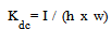 | (1) |
where, I, h and w are Impact Energy , breadth and width of the specimen.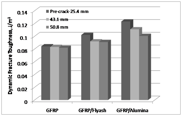 | Figure 5. Variation of dynamic fracture toughness with the specimens |
Fig. 5 shows the value of average dynamic fracture toughness for different specimen of different composition, such as flyash/GFRP, alumina/GFRP and GFRP composites with the variation in initial crack length ranging from 25.4, 43.1, 50.8 mm, respectively. It can be observed from the graph that dynamic fractures toughness of GFRP composite is lower than the flyash/GFRP and alumina /GFRP samples. Thus, samples of alumina have higher dynamic fracture toughness value, which has been explained with the help of SEM images of the samples.In all cases the value of average dynamic fracturetoughness of alumina samples are more than the flyash/GFRP and GFRP samples. This indicates that alumina particles increase the interface bond strength between epoxy resins, which increase the toughness of GFRP composites[7].
3.3. Microscopy Analysis
SEM images for GFRP sample shows matrix failure and de-bonding as visible in Figure 6. There is no fibre breakage in the de-lamination area. The fibres are shown in micrograph by region A. The matrix left after de-bonding is shown by region B.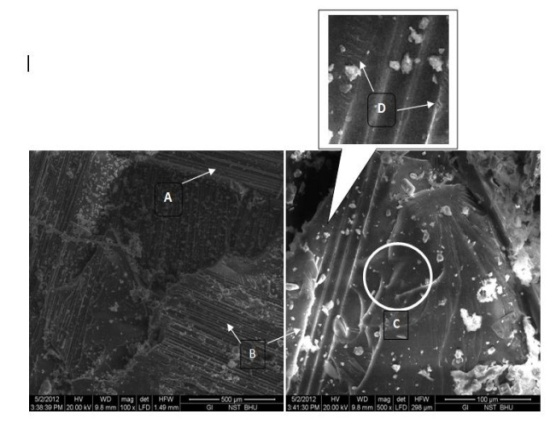 | Figure 6. SEM images for fractured specimen of GFRP composite |
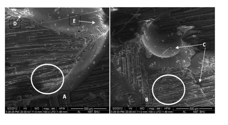
There is considerable brittle failure of matrix as shown by region C. In Figure 7, minute crack flow lines are seen around the de-bonded region D because the energy istransmitted through the matrix to the fibre resulting in de-bonding. De-bonding shows weak fibre-matrix interface[7, 8].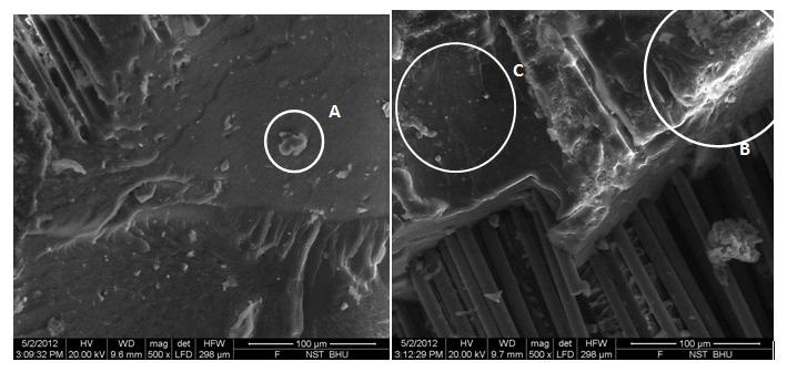 | Figure 7. SEM images for fractured specimen of flyash/GFRP composite |
SEM analysis of the Fly-ash specimen shows distribution of fly ash particles in the matrix, resin fly ash interface, glass fibre distribution in the matrix, glass fibre matrix interface, deformation behaviour etc[9]. This appeared that the maximum cracks are visible in the flayash/epoxy resin rich area, as shown in Fig. 8.It was observed that the fly-ash particles basically contain the metal oxide, as the particles are not spherical (Fig. 7-A). Also the mixing is rather heterogeneous, containing the lumps of the fly-ash (Fig. 7-A). The fly-ash sites where the large clusters were there acted as the site ofstress-concentration, resulting in the initiation of cracks (Fig. 7 - B) On the other hand, where the particles are well distributed and are small, and the area resisted the dislocation’s movement.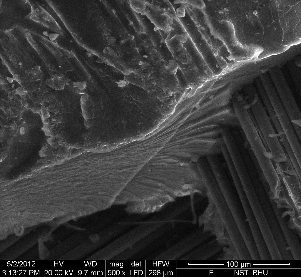 | Figure 8. Flyash mixed resin fractured in different plane |
 | Figure 9. SEM images for fractured specimen of alumina/GFRP composite |
SEM images for alumina/GFRP composite sampleindicate that there is no fibre failure in the de-lamination area[10]. There is significant de-bonding between fibre and matrix as shown by region A and B. The matrix underwent brittle failure as shown by C in Figure 9. The fracture toughness of sample improved considerably because the alumina particles converted into nano particles leading to large increase in surface area. This increase in surface area results in absorption of large amount of impact energy[11]. However, as visible from the SEM there was improper mixing of alumina leading to clusters. These clusters acted as stressconcentration point shown by D. As cluster size decreases crack flow lines are visible as shown by E. Small voids are also visible.
4. Conclusions
The experimental results confirmed that the addition of filler improved the toughness of GFRP composite under dynamic loading. In the case of alumina, dynamic fracture toughness, KdC, was more than the flyash filled GFRP composites, because, the shape and size of fillers play a key role in changing the toughness of the matrix. Also, micrographs showed that cracks were arrested by the particles and most of the fibres fractured due to increase of interface bond strength.
ACKNOWLEGEMENTS
The authors would like to thank Prof. O.N. Srivastava, Department of Physics, BHU, Varanasi for providing the SEM facilities. Also, authors are thankful to Mr. KaliPrasad, Mechanic, Mr. R. P. Singh, Lab Attended, Experimental Mechanics Laboratory, Department of MechanicalEngineering, Indian Institute of Technology, BHU, Varanasi, India for their supports during the experimental work.
References
| [1] | Y Hirai, H Hamada, JK Kim, Impact response of woven glass-fabric composites-I Effect of fiber surface treatment, Composites Science and Technology, 58, 91-104, 1998. |
| [2] | Y Hirai, H Hamada, JK Kim, Impact response of woven glass-fabric composites-II Effect of temperature, Composites Science and Technology, 58, 119-128, 1998. |
| [3] | JK Kim, YW Mai, Engineered interfaces in fiber reinforced composites, 1st ed. New York, Elsevier Sciences, 1998. |
| [4] | JK Kim, ML Sham, Impact and delamination failure of woven fabric composites, Composites Science and Technology, 60, 745-761, 2001. |
| [5] | J Li, JK Kim, Percolation threshold of conducting polymer composites containing 3D randomly distributed graphite nanoplatelets, Composites Science and Technology, 67, 2114-2120, 2007. |
| [6] | FS Liao, AC Su, TCJ Hsu, Vibration damping of interleaved carbon fiber-epoxy composite beams, J. of Composite Materials, 28, 1840-1854, 1994. |
| [7] | JK Kim, C Baillie, YW Mai, Fracture toughness of CFRP with modified epoxy resin matrices, Composites Science and Technology, 43, 263-297, 1992. |
| [8] | SU Khan, JK Kim, Impact and delamination failure of multiscale carbon nanotubes-fiber reinforced polymer composites- A review, Int. J. of Aeronautical and Space Sci. 12 (2), 115-133, 2011. |
| [9] | M Hojo, S Matsuda, M Tanaka, S. Ochiai, A Murakami, Mode I delamination fatigue properties ofinterlayer-toughened CF/epoxy laminates, Composites Science and Technology, 66, 665-675, 2006. |
| [10] | K Iqbal, SU Khan, A Munir, JK Kim, Impact damage resistance of CFRP and nanoclay-filled epoxy matrix, Composites Science and Technology, 69, 1949-1957, 2009. |
| [11] | D Alhazov, E Zussman, Study of the energy absorption of laminated glass using carbon nanotubes, Composites Science and Technology, 72, 681-687, 2012. |
 Abstract
 Reference
 Full-Text PDF
 Full-Text HTML