Engr. Nasrin Ferdous, Engr. Reashad Bin Kabir
Lecturer, Dept. of Apparel Manufacturing Management & Technology, Shanto-Mariam University of Creative Technology
Correspondence to: Engr. Reashad Bin Kabir, Lecturer, Dept. of Apparel Manufacturing Management & Technology, Shanto-Mariam University of Creative Technology.
| Email: |  |
Copyright © 2012 Scientific & Academic Publishing. All Rights Reserved.
Abstract
Geotextiles particularly refers to permeable fabric or synthetic material, woven or non-woven, which can be used with geotechnical engineering material. They apply to a broad range of civil engineering construction, paving, drainage and other applications. Geotextiles are extensively used with soil, rock, earth or any other geotechnical engineering-related material. In any one application, a Geotextile may be performing several of these functions. In Erosion control, the Geotextile protects soil surfaces from the Tractiveforces of moving water or wind and rainfall Erosion. On the other hand a Geotextile serves to control Sediment when it stops particles suspended in surface fluid flow while allowing the fluid to pass through. After some period of time, particles accumulate against the Geotextile, reducing the flow of fluid and increasing the pressure against the Geotextile. On the whole this paper discusses the roles of Geotextile in Erosion and Sediment control.
Keywords:
Geotextile, Erosion, Erosion Control, Sediment, Sediment Control
Cite this paper: Engr. Nasrin Ferdous, Engr. Reashad Bin Kabir, The Roles of Geotextile in Erosion & Sediment Control, International Journal of Clothing Science, Vol. 2 No. 1, 2013, pp. 1-8. doi: 10.5923/j.clothing.20130201.01.
1. Introduction
Geotextiles can be characterised as being either woven or non-woven. Most woven geotextiles are formed by interlacing two or more sets of yarns, fibers or filaments where they pass each other at right angles[1]. Specific weaving methods create four main types of geotextiles: monofilament slit film, multifilament and fibrillated. Monofilament geotextiles offer little resistance to through- flow of water and are generally made from polyethylene (HDPE) or polypropylene (PP). Standard geotextiles are semi-inert materials with predominantly physical properties [2].A multifilament yarn consists of many fine continuous filaments that are held together by twisting of the strands. Fibrillated tapes are made by splitting and twisting extruded films. Woven slit films are produced with yarns formed by longitudinally splitting of a polymeric film to form a slit tape yarn. However, this type of woven geotextile is not suitable for most drainage and filtration applications[3].Non-woven geotextiles are generally not as strong as their equivalent woven geotextiles, but they exhibit better filtration and separation properties[4]. For this reason, nonwoven geotextiles are the preferred for permeable paving applications.The majority of manufacturers use polypropylene in the construction of their geotextiles, because polyester deteriorates over time under both acidic and alkaline conditions. However, the degradation is more severe under alkaline conditions, which are rarely the case in urban runoff [5, 6].Erosion is the wearing away of the land surface by running water, wind, ice, or other causes. Soil erosion is usually caused by the force of water falling as raindrops and by the force of water flowing in rills and streams. Raindrops falling on bare or sparsely vegetated soil detach soil particles. Water running along the surface of the ground picks up these particles and carries them along as it flows downhill towards a stream system.Sedimentation is the deposition of soil particles that have been transported by water and wind. The quantity and size of the material transported increases with the velocity. Sedimentation occurs when the medium, air or water, in which the soil particles are carried, is sufficiently slowed long enough to allow particles to settle out. Heavier particles, such as gravel and sand, settle out sooner than do fine particles, such as clay.
2. Literature Review
2.1. Functions of Geotextiles
The functions of geotextiles are usually divided into five main categories: separation, filtration, drainage, protection and reinforcement. British guidance on the properties of geotextiles for use in drainage systems and in trafficked areas is given in BS EN 13252:2001[7] and BS EN 13249:2001[8]. These standards have subsequently been interpreted by the concrete and aggregate industry operating in Britain[5]. The ability of a geotextile to retain fines (e.g., suspended solids) depends primarily on its opening size[9]. Permeability tests for geotextiles may differ between 36 and 120 L/(m2s), and are generally a function of the weight and thickness of the geotextile[10]. This test is of great relevance when assessing the suitability of a geotextile for its suspended solids retention potential within a permeable pavement system[17]. The geotextile layer also encourages microbial activity in this area, leading to an improved treatment of runoff due to biological degradation processes[11, 12]. Furthermore, the geotextile also prevents fine particles (partly responsible for clogging) in the bedding layer from moving downwards into the aggregate, subsequently creating air pockets within the bedding layer, contributing to apotentially structurally unstable surface[13].However, the literature review indicates that only a relatively small number of these experiments included an upper geotextile layer[14, 15, and 16].
3. Erosion
Erosion is caused by a group of physical and chemical processes by which the soil or rock material is loosened, detached, and transported from one place to another by running water, waves, wind, moving ice, or other geological sheet and bank Erosion agents. Clayey soils are less erodible than fine sands and silts. See figure 1.However, for aesthetic or economic reasons, articulated concrete mattresses, gabions, and precast cellular blocks have also been used to cover the Geotextile. The velocity of the current, the height and frequency of waves and the erodibility of the bank determine whether bank protection is needed. The Geotextiles used in bank protection serve as a filter.
3.1. Special Design Considerations
3.1.1. Based on Purpose
The types of Geotextiles available are vast; therefore, the selected fabric should match its purpose. Also, State or local requirements, design procedures, and any other applicable requirements should also be consulted. In the field, important concerns include regular inspections to determine if cracks, tears, or breaches are present in the fabric and appropriate repairs should be made.
3.1.2. Durability
The term includes chemical, biological, thermal, and ultraviolet (UV) stability. Streams and runoff may contain materials that can be harmful to the Geotextile. When protected from prolonged exposure to UV light, the common synthetic polymers do not deteriorate or rot in prolonged contact with moisture.
3.1.3. Strength and Abrasion Resistance
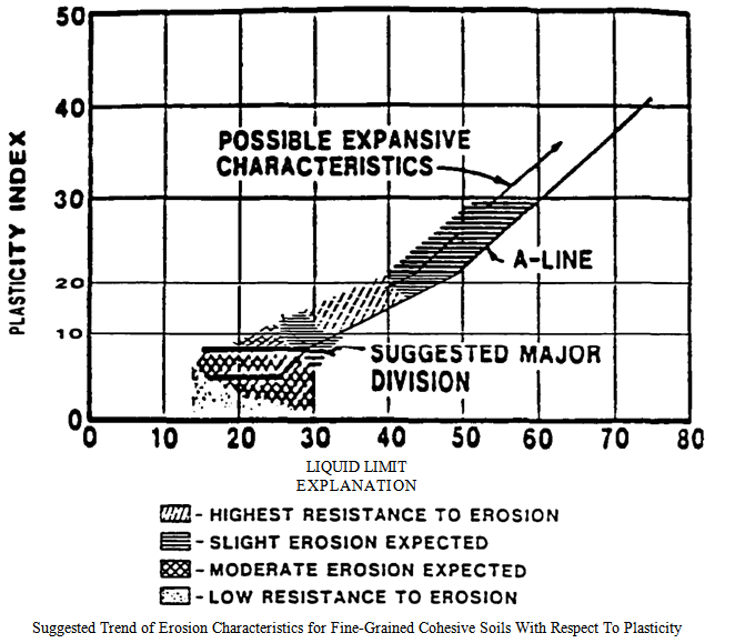 | Figure 1. Relationship between Atterberg limits and expected Erosion potential |
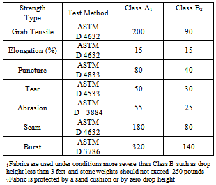
The required properties will depend on the specific application for example the type of the cover material to be used (riprap, sand bags, concrete blocks, etc.), the size, weight, and shape of the armor stone, the handling placement techniques (drop height), and the severity of the conditions (stream velocity, wave height, rapid changes of water level, etc.). Abrasion can result from movement of the cover material as a result of wave action or currents. Strength properties generally considered of primary importance are tensile strength, dimensional stability, tearing, puncture, and burst résistance. Table 1 gives recommended minimum strength values.Table 1. Recommended Geotextile Minimum Strength Requirements
 |
| |
|
3.1.4. Cover Material
The cover material (gravel, rock fragments, riprap, armor stone, concrete blocks, etc.) is a protective covering over the Geotextile that minimizes or dissipates the hydraulic forces, protects the Geotextile from extended exposure to UV radiation, and keeps it in intimate contact with the soil. The type, size, and weight of cover material placed over the Geotextile depend on the kinetic energy of water. Cover material that is lightweight in comparison with the hydraulic forces acting on it may be moved. By removing the weight holding the Geotextile down, the ground-water pressure may be able to separate the Geotextile from the soil. When no longer constrained, the soil erodes. The cover material must be at least as permeable as the Geotextile. If the cover material is not permeable enough, a layer of fine aggregate (sand, gravel, or crushed stone) should be placed between it and the Geotextile.
3.1.5. Anchorage
At the toe of the stream bank, the Geotextile and cover material should be placed along the bank to an elevation below mean low water level to minimize Erosion at the toe. Placement to a vertical distance of 3 feet below mean low water level, or to the bottom of the streambed for streams shallower than 3 feet, is recommended. At the top of the bank, the Geotextile and cover material should either be placed along the top of the bank or with 2 feet vertical freeboard above expected maximum water stage. If strong water movements are expected, the Geotextile needs to be anchored at the crest and toe of the stream bank (fig 2).
3.2. Construction Considerations
3.2.1. Site Preparation
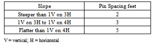
The surface should be cleared of vegetation, large stones, limbs, stumps, trees, brush, roots, and other debris and then graded to a relatively smooth plane free of obstructions, depressions, and soft pockets of materials. 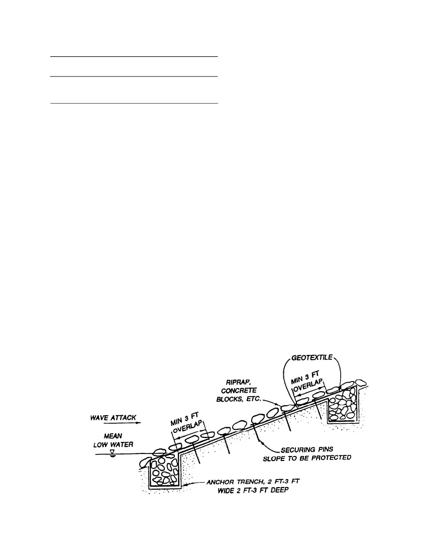 | Figure 2. Pin Spacing Requirements in Erosion Control Applications |
 | Figure 3. Use of Geotextiles near small hydraulic structures |
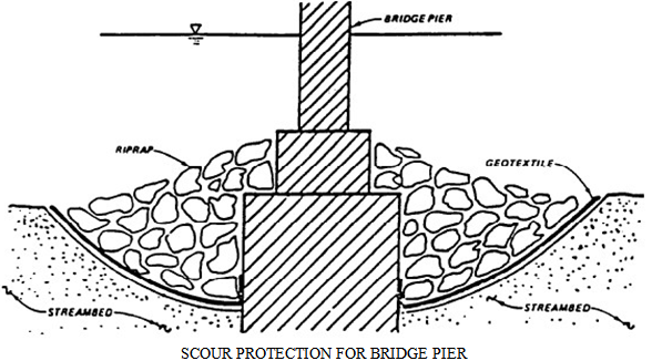 | Figure 4. Use of Geotextiles around piers and abutments |
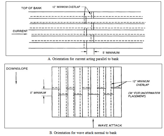 | Figure 5. Geotextile placement for currents acting parallel to bank or for wave attack on the bank |
3.2.2. Placement of Geotextiles
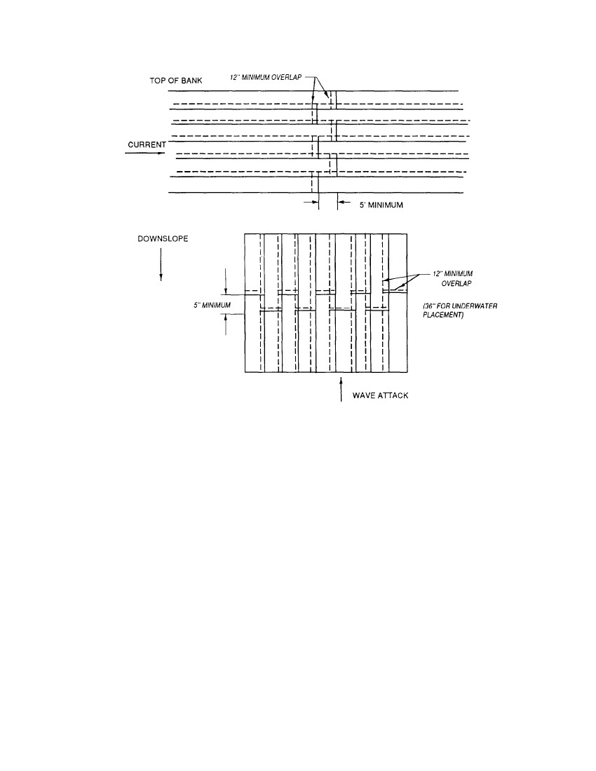
The Geotextile is unrolled directly on the smoothly graded soil surface. It should not be left exposed to W deterioration for more than 1 week in case of untreated Geotextiles, and for more than 30 days in case of W protected and low UV susceptible polymer Geotextiles. The Geotextile should be loosely laid, free of tension, folds, and wrinkles. When used for stream bank protection, where currents acting parallel to the bank are the principal Erosion forces, the Geotextile should be placed with the longer dimension (machine direction) in the direction of anticipated water flow. The upper strips of the Geotextile should overlap the lower strips (fig 5). When used for wave attack or cut and fill slope protection, the Geotextile should be placed vertically down the slope (fig 5), and the upslope strips should cover the down slope strips. Stagger the overlaps at the ends of the strips at least 5 feet. The Geotextile should be anchored at its terminal ends to prevent uplift or undermining. For this purpose, key trenches and aprons are used at the crest and toe of the slope.
3.2.3. Overlaps, Seams, Securing Pins
Adjacent Geotextile strips should have a minimum overlap of 12 inches along the edges and at the end of rolls. For underwater placement, minimum overlap should be 3 feet. Specific applications may require additional overlaps. Sewing, stapling, heat welding, or gluing adjacent panels, either in the factory or on site, are preferred to lapping only. Sewing has proved to be the most reliable method of joining adjacent panels. It should be performed using polyester, polypropylene, kevlar or nylon thread. The seam strength for both factory and field seams should not be less than 90 percent of the required tensile strength of the unaged Geotextile in any principal direction. Geotextiles may be held in place on the slope with securing pins prior to placing the cover material. These pins with washers should be inserted through both strips of the overlapped Geotextile along a line through the midpoint of the overlap. The pin spacing, both along the overlaps or seams, depends on the slope, as specified in table 2.Table 2. Pin Spacing Requirements in Erosion Control Applications
 |
| |
|
Steel securing pins, 3/16 inch in diameter, 18 inches long, pointed at one end, and fitted with a 1.5-inch metal washer on the other have performed well in rather firm soils.Longer pins are advisable for use in loose soils. The maximum slope on which Geotextiles may be placed will be determined by the friction angles between the natural-ground and Geotextile and cover- material and Geotextile. The maximum allowable slope in no case can be greater than the lowest friction angle between these two materials and the Geotextile.
3.2.4. Placement of Cover Material on Geotextile
For sloped surfaces, placement of the cover stone or riprap should start from the base of the slope moving upward and preferably from the center outward to limit any partial movement of soil because of sliding. In no case should drop heights which damage the Geotextile be permitted. Testing may be necessary to establish an acceptable drop height.
4. Precipitation Runoff Collection and Diversion Ditches
A diversion ditch is an open, artificial, gravity flow channel which intercepts and collects precipitation runoff, diverts it away from vulnerable areas, and directs it toward stabilized outlets. A Geotextile or revegetation mat can be used to line the ditch. It will retard Erosion in the ditch, while allowing grass or other protective vegetation growth to take place. The mat or Geotextile can serve as additional root anchoring for some time after plant cover has established itself if UV resistant Geotextiles are specified. Some materials used for this purpose are designed to degrade after grass growth takes place. The Geotextile can be selected and specified using physical properties indicated in table 1. Figure 6 shows a typical example.
5. Miscellaneous Erosion Control
Figure 3 and 4 show examples of Geotextile applications in Erosion control at drop inlets and culvert outlets and scour protection around bridges, piers, and abutments. Design criteria similar to that used for bank protection should be used for these applications.
6. Sediment Control
Silt fences and silt curtains are Sediment control systems using Geotextiles.
6.1. Silt Fence
A silt fence is a temporary vertical barrier composed of a sheet of Geotextile supported by fencing or simply by posts, as illustrated in figure 3. The lower end of the Geotextile is buried in a trench cut into the ground so that runoff will not flow beneath the fence. The purpose of the permeable Geotextile silt fence is to intercept and detain Sediment from unprotected areas before it leaves the construction site. Silt fence are sometimes located around the entire down slope portion or perimeter of urban construction sites. Short fences are often placed across small drainage ditches (permanent or temporary) constructed on the site. Both applications are intended to function for one or two construction seasons or until grass sod is established. The fence reduces water velocity allowing the Sediment to settle out of suspension.
6.1.1. Design Concepts
A silt fence consists of a sheet of Geotextile and a support component. The support component may be a wire or plastic mesh support fence attached to support posts or in some cases may be support posts only. The designer has to determine the minimum height of silt fences, and consider the Geotextile properties (tensile strength, permeability) and external factors (the slope of the surface, the volume of water and suspended particles which are delivered to the silt fence, and the size distribution of the suspended particles). Referring to figure 8, the total height of the silt fence must be greater than h1 + h2 + h; where h1 is the height of Geotextile necessary to allow water flowing into the basin to flow through the Geotextile, considering the permeability of the Geotextile; h2 is the height of water necessary to overcome the threshold gradient of the Geotextile and to initiate flow. For most expected conditions, h1 + h2 is about 6 inches or less. The silt fence accomplishes its purpose by creating a pond of relatively still water which serves as a Sedimentation basin and collects the suspended solids from the runoff. The useful life of the silt fence is the time required to fill the triangular area of height h (fig 7) behind the silt fence with Sediment. The height of the silt fence Geotextile should not exceed 3 feet. 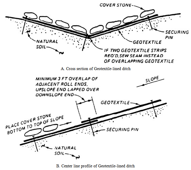 | Figure 6. Ditch Liners |
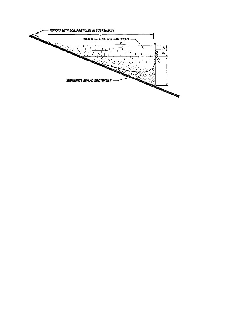 | Figure 7. Sedimentation behind silt fence |
6.1.2. Design for Maximum Particle Retention
Geotextiles selected for use in silt fences should have an AOS that will satisfy the following equation with a limiting value equal to the No. 120 sieve size.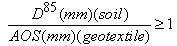 ……..…… ……………Eqn (1)A minimum of 90-pound tensile strength (ASTM D 4632 Grab Test Method) is recommended for use with support posts spaced a maximum of 8 feet apart.
6.1.3. Design for Filtration Efficiency
The Geotextile should be capable of filtering most of the soil particles carried in the runoff from a construction site without unduly impeding the flow. ASTM D 5141 presents the laboratory test used to determine the filtering efficiency and the flow rate of the Sediment-filled water through the Geotextile.
6.1.4. Required Geotextile Properties
The Geotextile used for silt fence must also have:1. Reasonable Puncture and Tear Resistance to Prevent Damage by Floating Debris and to Limit Tearing where Attached to Posts and Fence2. Adequate Resistance to UV Deterioration and Biological, Chemical, and Thermal Actions for the Desired Life of the Fence
6.1.5. Construction Considerations
1. Silt Fences should be Constructed after the Cutting of Trees but before Having any Sod Disturbing Construction Activity in the Drainage Area2. It is a Good Practice to Construct the Silt Fence Across a Flat Area in the Form of a HorseshoeThis aids in the ponding of the runoff, and increases the strength of the fence. Prefabricated silt fence sections containing Geotextile and support posts are commercially available. They are generally manufactured in heights of 18 and 36 inches. At the lower portion of the silt fence, the Geotextile is extended for burying anchorage.
6.2. Silt Curtains
A silt curtain is a floating vertical barrier placed within a stream, lake, or other body of water generally at runoff discharge points. It acts as a temporary dike to arrest and control turbidity. By interrupting the flow of water, it retains suspended particles; by reducing the velocity, it allows Sedimentation. A silt curtain is composed of a sheet of Geotextile maintained in a vertical position by flotation segments at the top and a ballast chain along the bottom. A tension cable is often built into the curtain immediately above or below the flotation segments to absorb stress imposed by currents and other hydrodynamic forces. Silt curtain sections are usually about 100 feet long and of any required width. An end connector is provided at each end of the section for fastening sections together. Anchor lines hold the curtain in a configuration that is usually U-shaped, circular, or elliptical. The design criteria and properties required for silt fences also apply to silt curtains.Silt curtains should not be used for:i. Operations in open Ocean.ii. Operations in currents exceeding 1 knot.iii. Areas frequently exposed to high winds and large breaking waves.iv. Around hopper or cutter head dredges where frequent curtain movement would be necessary.
7. Conclusions
In spite of having so many materials now a day’s Geotextile are getting popular day by day in Erosion and Sediment control. When selecting a Geotextile a designer must take into account not only the mechanical and hydraulic properties of the Geotextile at the point of manufacture, but the proven longevity of the properties in the site environment, both prior to installation and for the duration of the design. The use of Geotextiles manufactured from the bi-products of other manufacturing processes must be undertaken with extreme caution as the long term performance can never be fully known.
References
| [1] | Holtz, R.D. Geosynthetics for soil reinforcement. In Frontier Technologies for Infrastructures Engineering: Structures and Infrastructures; Chen, S., Ang, A.H., Eds.; Taylor and Francis Group: London, UK, 2009. |
| [2] | Scholz, M. Wetland Systems to Control Urban Runoff; Elsevier: Amsterdam, The Netherlands, 2006. |
| [3] | John, N.W.M. Geotextiles; Blackie and Son: London, UK, 1987. |
| [4] | Cook, D.I. Geosynthetics; Rubber and Plastics Research Association Technology Limited: Shrewsbury, UK, 2003. |
| [5] | Scholz, M. Wetland Systems—Storm Water Management Control; Springer Verlag: Berlin, Germany, 2010. |
| [6] | Boving, T.B.; Stolt, M.H.; Augenstern, J.; Brosnan, B. Potential for localized groundwater contamination in a porous pavement parking lot setting in Rhode Island. Environ. Geol. 2008, 55, 571–582. |
| [7] | BSI. Geotextiles and Geotextile-related Products. Characteristics Required for Use in Drainage Systems; The British Standards Institution: London, UK, 2001; Standard BS EN13252:2001.Availableonline:http://shop.bsigroup.com/ProductDetail/?pid=000000000030144789 (accessed on 10 May 2012). |
| [8] | The British Standards Institution (BSI). Geotextiles and Geotextile-related Products. Characteristics Required for Use in the Construction of Roads and Other Trafficked Areas (Excluding Railways and Asphalt Inclusion); BSI: London, UK, 2001; Standard BS EN13249:2001.Available online: http://shop.bsigroup.com/ProductDetail/?pid= 000000000030144365 (accessed on 10 May 2012). |
| [9] | Narejo, D.B. Opening size recommendations for separation geotextiles used in pavements. Geotext. Geomemb. 2003, 21, 257–264. |
| [10] | 10. Shukla, S.K. Geosynthetics and Their Applications; Thomas Telford Publishing: London, UK, 2002. |
| [11] | Tota-Maharaj, K.; Scholz, M.; Ahmed, T.; French, C.; Pagaling, E. The synergy of permeable pavements and geothermal heat pumps for stormwater treatment and reuse. Environ. Technol. 2010, 31, 1517–1531. |
| [12] | Coupe, S.J.; Smith, H.G.; Newman, A.P.; Pühmeier, T. Biodegradation and microbial diversity within permeable pavements. Eur. J. Protistol. 2003, 39, 495–498. |
| [13] | Scholz, M.; Grabowiecki, P. Review of permeable pavement systems. Build. Environm. 2007, 42, 3830–3836. |
| [14] | Newman, A.P.; Pühmeier, T.; Kwok, V.; Lam, M.; Coupe, S.J.; Shuttleworth, A.; Pratt, C.J. Protecting groundwater with oil-retaining pervious pavements: Historical perspectives, limitations and recent developments. Quart. J. Eng. Geol. Hydrogeol. 2004, 37, 283–291. |
| [15] | Pratt, C.J.; Mantle, D.G.; Schofield, P.A. UK research into the performance of permeable pavement, reservoir structures in controlling stormwater discharge quantity and quality. Water Sci. Technol. 1995, 32, 63–69. |
| [16] | Tota-Maharaj, K.; Scholz, M. Artificial neural network simulation of combined permeable pavement and earth energy systems treating storm water. J. Environ. Eng. ASCE 2012, 138, 499–509. |
| [17] | Miklas Scholz. Water Quality Improvement Performance of Geotextiles Within Permeable Pavement Systems. Water 2013, 5, 462-479; doi: 10.3390/w5020462 |
 Abstract
 Reference
 Full-Text PDF
 Full-text HTML