-
Paper Information
- Paper Submission
-
Journal Information
- About This Journal
- Editorial Board
- Current Issue
- Archive
- Author Guidelines
- Contact Us
American Journal of Chemistry
p-ISSN: 2165-8749 e-ISSN: 2165-8781
2015; 5(1): 28-39
doi:10.5923/j.chemistry.20150501.05
Corrosion Protection Study for Caron Steel in Seawater by Coating with SiC and ZrO2 Nanoparticles
 Abstract
 Reference
 Full-Text PDF
 Full-text HTML
Khulood Abid Saleh Al-Saadie1, Haider A. Yousif Al-Mashhdani2
1University of Baghdad, College of Science, Department of Chemistry, Baghdad, Iraq
2Al-Rasheed University College, Department of Dentistry, Baghdad, Iraq
Correspondence to: Haider A. Yousif Al-Mashhdani, Al-Rasheed University College, Department of Dentistry, Baghdad, Iraq.
| Email: |  |
Copyright © 2015 Scientific & Academic Publishing. All Rights Reserved.
The corrosion protection by coating carbon steel (C.S) with SiC and ZrO2 NPs was investigated in presence of different Polyacrlyic acid (PAA) concentration. Electrophoretic deposition (EPD) method using was applied ethanol suspensions and polyacrlyic acid (PAA) as stabilizing agent. The deposition of SiC and ZrO2 NPs was occurred on the carbon steel (C.S) alloy as cathode. Coated C.S by NPs in presence of PAA revealed a good corrosion protection efficiency even at temperature ranged (298- 328)K in seawater (3.5% NaCl). Results show that using PAA in suspension coat increased PE% when compared with PE% in absence of PAA and gaves resistance in above temperature range. Kinetic parameters (activation energy and pre-exponential factor) were calculated and discussed. Also, thermodynamic Values ΔG and ΔH were calculated and it shows that corrosion reaction was spontaneous and exothermic in nature. The surface morphology was examined by AFM techniques; the resulted AFM images were detect the morphology of surface and the particles size of coat layers which range from 60-103 nm.
Keywords: Corrosion protection, Coating, SiC Nanoparticles, ZrO2 NPs, PAA
Cite this paper: Khulood Abid Saleh Al-Saadie, Haider A. Yousif Al-Mashhdani, Corrosion Protection Study for Caron Steel in Seawater by Coating with SiC and ZrO2 Nanoparticles, American Journal of Chemistry, Vol. 5 No. 1, 2015, pp. 28-39. doi: 10.5923/j.chemistry.20150501.05.
Article Outline
1. Introduction
- Corrosion is an electrochemical phenomenon and is accompanied by the flow of electrical current and its degradation of materials and structures is one of the important issues that lead to depreciation of investment goods. The damages by corrosion generate not only high costs for inspection, repairing and replacement, but in addition these constitute a public risk [1]. Seawater (3.5% NaCl) solutions are widely used in industry, which leads to corrosive attack. The corrosion protection by coats is one of the most common effective and economic methods to protect metals in acid media [2-8]. Nanomaterials are important due to their unique properties that may lead to new and exciting applications. Nanoparticle coatings possess good thermal and electrical properties and they are resistant to oxidation, corrosion, erosion and wear in high temperature environments [9]. These property is very important factor in the applications such as pipelines, castings and automotive industry.Electrophoretic deposition (EPD) is a simple method for the formation of a coating nanomaterials on an electrode using a stable suspension in a direct current (DC) field [10, 11]. EPD technique was used to coat silicon carbide (SiC) particles on metal surfaces. Both sparse SiC particles and dense particle coating layers were fabricated on metal surface. Detailed analysis shows that SiC particles are bonded and compacted well with the metal surface [12], also used Zirconium oxide (ZrO2) [13] & alumina (Al2O3) [14] nanoparticles lead to similar layers.However, in aqueous-based EPD suspensions, method presented several disadvantages, for example, corrosion of the electrodes and gas bubbles produced by electrolysis of water at the electrodes during the EPD, which would reduce the density of deposited layer [15-18]. To avoid the formation of gas bubbles, non-aqueous suspensions became a preferred choice. Among the non-aqueous media, ethanol was the common dispersing medium for EPD [19]. In this research, ethanol was used as a solvent for EPD because of its less toxicity, less harmfulness to the environment, and good volatility.EPD modified by using polymer as charging and stabilizing agent, acted effectively as colloidal particles during EPD [20]. Electrophoretic deposition (EPD) with ethanol as suspension medium and poly(acrylic acid) (PAA) as polymeric charging agent give good protection. In addition, the suspension must possess a high stability, thus charged polymers and surfactants were added to the suspension [21-23]. These additives, which were adsorbed onto the surfaces of ceramic particles, could generate steric and electrostatic stabilization and prevent particles agglomeration [24].
2. Materials and Methods
2.1. Materials
- The steel used in this study is a carbon steel (C45) with a chemical composition (in wt%) of 0.42% C, 0.40 % Si, 0.50% Mn, 0.045% S, 0.40% Cr, 0.045% P, 0.40% Ni, 0.0.1% Mo and the remainder is iron (Fe). The carbon steel samples were pre-treated prior to the experiments by grinding with emery paper SiC (120, 600 and 1200); rinse with distilled water, degreased in acetone, washed again with distilled water and then dried at room temperature before used synthized seawater. The seawater solution was prepared by dissolved 35 g NaCl in 1L distilled water. SiC Nanoparticles were used in size range (20-30nm, Hongwu nanometer, purity 99.9%), ZrO2 (40-50nm, Hongwu nanometer, purity 99.9%) and iodine was used in 99.8% purity (Aldrich).
2.2. Preparation of Emulsion Solution
- Emulsion solution was prepared by adding 1% nanoparticles (NPs) (ZrO2orSiC) powder to ethanol as solvent [25] (adding 1.5 g NPs to 150 ml ethanol). To study the effect of adding different PAA% (0.1, 0.25, 0.5 & 1)% in emulsion solution (0.1, 0.25, 0.5, 1)g of PAA was added to in 100 ml ethanol respectively.To homogenize the solution, an ultrasonic (50W) stirrer was used to mixed the solution for 30 min. The solutions were applied for coating carbon steel (C45) pieces by using EPD technique method. Sometime few I2 were added to increase conductivity [26].
2.3. Electrophoresis Deposition of Emulsion Solution (Coating Samples)
- To deposit emulsion solution on a piece of carbon steel surfaces, deposition cell device was used. The electrodes were connected to a D.C power supply; it can be used in anodic or cathodic deposition by reversing electrodes of the power supply [27]. The deposition cell device composed of the following components:1. Beaker 250 ml capacity and cover contain two slit with distance between then equal to 1cm.2. Power supply used to supply constant direct current D.C voltage (0 – 20) V.3. An electrical circuit was connected by ammeter, respectively, to measure the current generated between the poles.4. Stainless steel rode used as inert electrode in deposition process cell [28].5. A piece of carbon steel catch by tong made of stainless steel fixed with 1cm distance between it and inert electrode.The deposition on C.S specimens were carried for (3,4,5 and 6) minutes, then all specimens thermally dried at 150℃ for 2 min.
2.4. Electrochemical Measurements
- The electrochemical measurements were carried out using Mlab (Germany, 2000) potentiostate and controlled by computer and MLabSci software which were used for data acquisition and analysis under static condition. The corrosion cell used had three electrodes, the reference electrode was a silver-silver chloride, platinum electrode was used as auxiliary electrode with 1 cm2 surface area of and the working electrode was carbon steel. All potentials given in this study were referred to this reference electrode. The working electrode was immersed in test solution for 15 minutes to a establish steady state open circuit potential (Eocp), then electrochemical measurements were performed in potential range (±200) mV. All electrochemical tests have been performed in aerated solutions at (208-328) K.
3. Result and Discussion
3.1. Polarization Curve
- Figure (1) shows the polarization curves of carbon steel coated with SiC and ZrO2 NPs in presence of various PAA%. It could be observed that both the cathodic and anodic reactions were suppressed with the addition of different PAA%, which suggests that coated by SiC and ZrO2 in presence of different PAA% reduced anodic dissolution and also retarded the oxygen reduction reaction effectively. Protection efficiencies (PE%) of all types of coating estimated by comparison with the measurements of the uncoated surface of carbon steel alloy using equations (1):
 | (1) |
 | (2) |
 | (3) |
3.2. Effect of PAA%
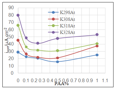
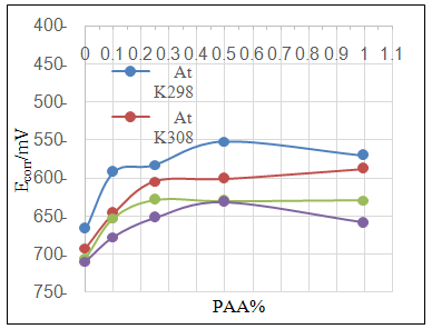
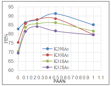
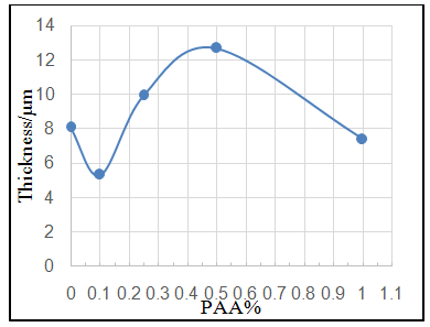
- Effect of different PAA concentration in the SiC NPs suspension solution, were investigated, PAA lead to increase the stability of suspension solution and increase the thickness of SiC NPs coat, with increase concentration of PAA in suspension. Adding 0.25% of PAA for the suspension of SiC coating lead to the lowest icorr value in temperature range (298- 328)K, as shown in figure (2-a).The corrosion potential (Ecorr) is shifted to the highest noble potential (positive direction) when C.S coated by SiC NPs with (0.25%) PAA. The protection efficiency for C.S specimens coated by SiC NPs in presence of different PAA% in seawater at different temperatures (298, 308, 318, 328)K were investigated, and the best PE% was obtained in presence of (0.25%) PAA at 298K. So (0.25%) PAA was perfect concentration added to suspension solution of coating which give PE% range between (99.65 – 96.7%) at temperatures range 298- 328 K, as shown in fig.2.
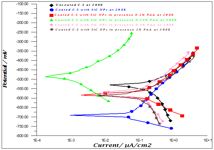 | Figure 1a. Polarization curves for C.S in 3.5% NaCl for uncoated and coated C.S with SiC NPs in absence and percent of different PAA% |
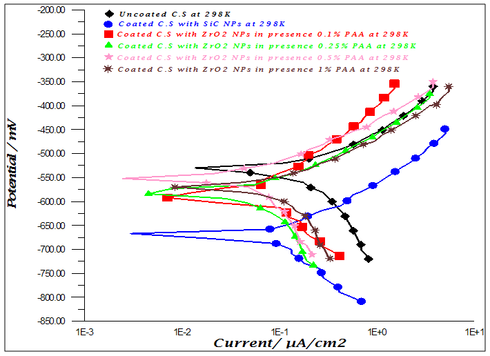 | Figure 1b. Polarization curves for C.S in 3.5% NaCl for uncoated and coated C.S with ZrO2 NPs in absence and percent of different PAA% |
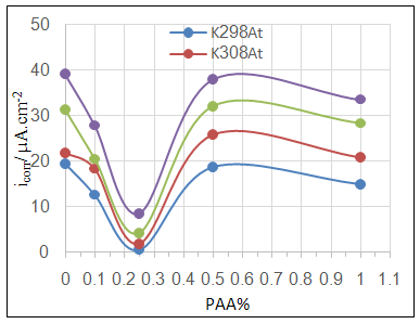 | Figure 2a. Effect of adding different PAA% to SiC NPs coating suspension on icorr |
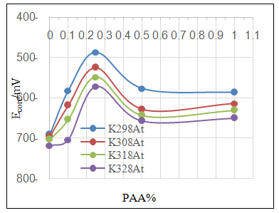 | Figure 2b. Effect of adding different PAA% to SiC NPs coating suspension on Ecorr |
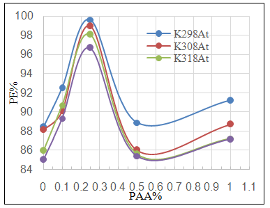 | Figure 2c. Effect of adding different PAA% to SiC NPs coating suspension on PE% |
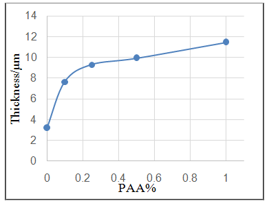 | Figure 2d. Effect of adding different PAA% to SiC NPs coating suspension on thickness of coat |
 | Figure 3a. Effect of adding different PAA% to ZrO2 NPs coating suspension on icorr |
 | Figure 3b. Effect of adding different PAA% to ZrO2 NPs coating suspension on Ecorr |
 | Figure 3c. Effect of adding different PAA% to ZrO2 NPs coating suspension on PE% |
 | Figure 3d. Effect of adding different PAA% to ZrO2 NPs coating suspension on thickness of coat |
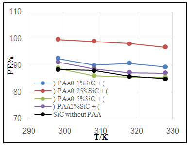 | Figure 4a. Effect of temperature on PE% of C.S coated by SiC NPs in absence and presence different PAA% |
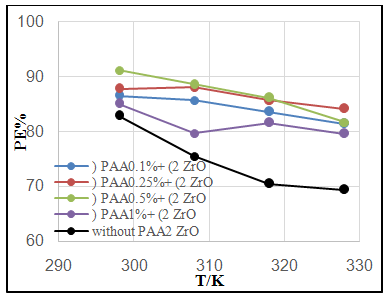 | Figure 4. Effect of temperature on PE% of C.S coated by a) SiC NPs and b) ZrO2 in absence and presence different PAA% |
3.3. Surface Porosity
- Surface porosity percentage fraction was estimated by potentiostatic polarization. In this case, the porosity percentage (P%) can be calculated using the following equation:
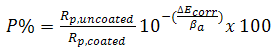 | (4) |
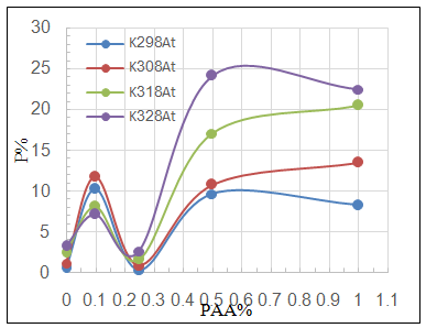 | Figure 5a. Variation of porosity percentage P% with PAA% at different temperatures for C.S coated by SiC NPs in absence and presence of different PAA% |
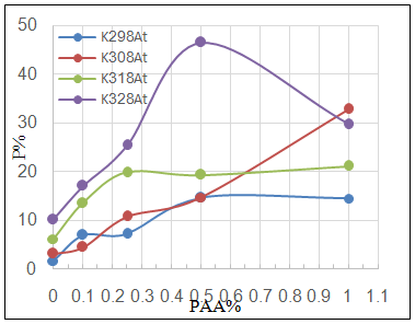 | Figure 5b. Variation of porosity percentage P% with PAA% at different temperatures for C.S coated by ZrO2NPs in absence and presence of different PAA% |
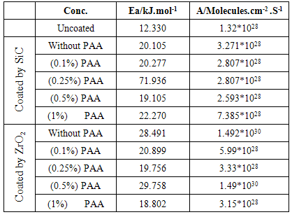
3.4. The Kinetic Studies
- The effect of temperature on the rate of C.S corrosion has been studied over the temperature range (293-308)K. Figure (6) shows logicorr plotted against the reciprocal of the absolute temperature (l/T) for the corrosion of coated and uncoated C.S alloy and with adding different PAA%. The relation was almost linear dependence between the corrosion rate (logicorr) and 1/T which can expressed as: [29]
 | (5) |
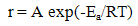 | (6) |
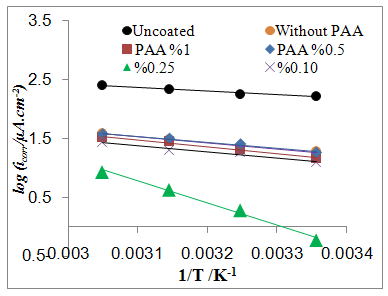 | Figure 6a. logicorr Vs 1/T for coated C.S with SiCNPs in absence and presence of different PAA% in 3.5% NaCl |
 | Figure 6b. logicorr Vs 1/T for coated C.S with ZrO2NPs in absence and presence of different PAA% in 3.5% NaCl |
|
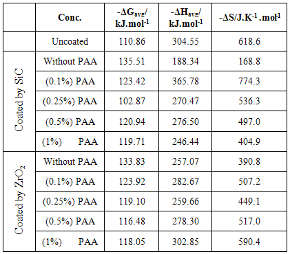
3.5. The Thermodynamic Studies
- The change in Gibbs free energy (ΔG) for the corrosion of C.S alloy specimens at a given temperature may be estimated from the following equation:
 | (7) |
 | (8) |
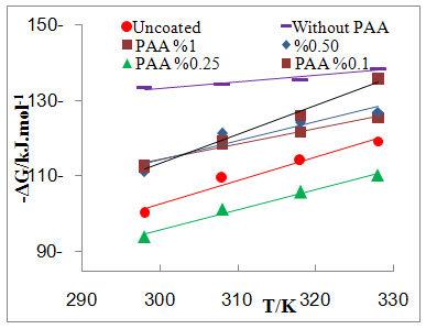 | Figure 7a. Plot of -∆G Vs T for coated C.S with SiCNPs in absence and presence of different PAA% in 3.5% NaCl |
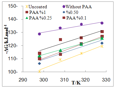 | Figure 7b. Plot of -∆G Vs T for coated C.S with ZrO2NPs in absence and presence of different PAA% in 3.5% NaCl |
|
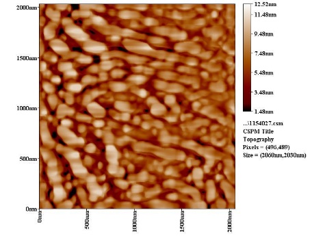
3.6. The Surface Morphology
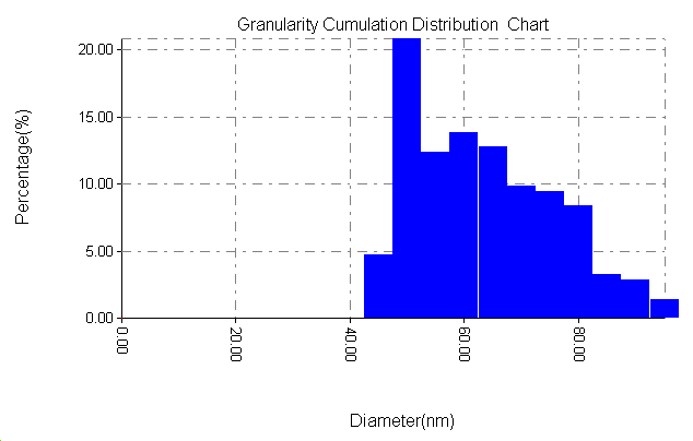
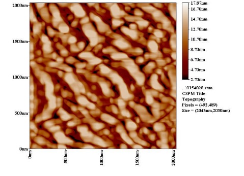
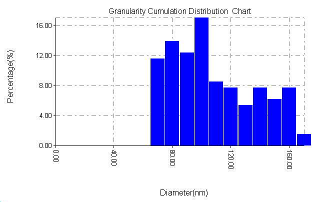
- The results of the Surface Morphology Analysis by AFM for coated by SiC, are shown in figure (8). The average roughness of layer SiC NPs without PAA was calculated as 60 nm, which nearly three times greater than the stating particles (20nm), but layers SiC NPs in presence 0.25% PAA only, show a degree of agglomeration of the nanoparticles due to adhesiveness of SiC NPs with PAA and the produced layer are higher density greater adhesive with larger particles. The particle size distribution is tabulated in figure (8b and 8d), it showed that the average particles size around 95.26 nm.
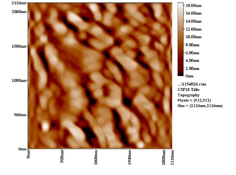 | Figure 8a. AFM section line image of SiC without PAA |
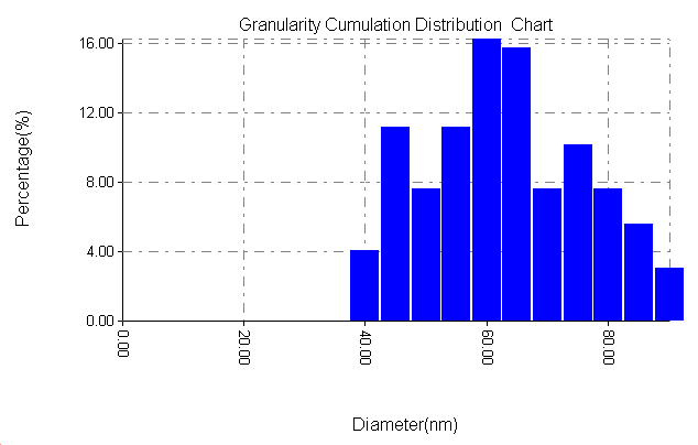 | Figure 8b. Particle size distribution of SiC without PAA |
 | Figure 8c. AFM section line image of SiC with PAA |
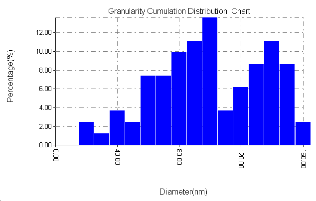 | Figure 8d. Particle size distribution of SiC with PAA |
 | Figure 9a. AFM section line image of ZrO2 without PAA |
 | Figure 9b. Particle size distribution of ZrO2 without PAA |
 | Figure 9c. AFM section line image of ZrO2 with PAA |
 | Figure 9d. Particle size distribution of ZrO2 with PAA |
4. Conclusions
- 1. The Electrophoretic Deposition (EPD) technique was successfully applied to coat C.S by SiC& ZrO2 nanoparticles.2. The protection efficiency of coated C.S by SiC NPs unaffected by temperatures but the protection efficiency for coated C.S by ZrO2 NPs affected with temperatures. 3. Added PAA in the suspension solution act as stabilizing agent and create NPs coated more smooth and resist to heat.4. The rate of corrosion increased with increasing temperatures ranged from 298 to 328 K. 5. After coated by NPs, Two important trends are evident. Firstly, the corrosion potential shifted toward more active value in coated carbon steel with NPs , Secondly, the corrosion current densities were significant reduced with coated by the two NPs.6. The protected by coated with SiC NPs without PAA was more resistant to corrosion comparison with the protected by coated with ZrO2 NPs.7. PAA increased the protection when added in suspension solution of coated. And adding (0.25%) PAA in suspension solution of SiC NPs lead to highest protection efficiency.8. The surface porosity percentage P%, generally increase with temperature increase, and adding different PAA% increase the P% because P% depended on RP and Ecorr.9. The activation energy of C.S alloys corrosion increase after coated.10. The corrosion reaction was spontaneous reaction (values of ΔG was negative) with exothermic reaction (values of ΔH was negative).11. The AFM images detection The Particles size increase after coated by different NPs in all cases.