-
Paper Information
- Paper Submission
-
Journal Information
- About This Journal
- Editorial Board
- Current Issue
- Archive
- Author Guidelines
- Contact Us
Architecture Research
p-ISSN: 2168-507X e-ISSN: 2168-5088
2020; 10(4): 93-101
doi:10.5923/j.arch.20201004.01
Received: Aug. 5, 2020; Accepted: Aug. 27, 2020; Published: Sep. 15, 2020

Exploration of Catenary Based Ferrocement Shell Structures: Form, Design and Architectural Interventions
 Abstract
 Reference
 Full-Text PDF
 Full-text HTML
Mohammad Arif Kamal1, Atul Setya2, Tejwant Singh Brar3
1Architecture Section, Aligarh Muslim University, Aligarh, India
2School of Architecture and Design, Galgotias University, Greater Noida, India
3Shushant School of Art and Architecture, Ansal University, Gurgaon, India
Correspondence to: Mohammad Arif Kamal, Architecture Section, Aligarh Muslim University, Aligarh, India.
| Email: |  |
Copyright © 2020 The Author(s). Published by Scientific & Academic Publishing.
This work is licensed under the Creative Commons Attribution International License (CC BY).
http://creativecommons.org/licenses/by/4.0/

The structure or a building is primarily defined by its form and material. The Catenary is a form defined by hanging chain which has been used over centuries to build arches, vaults etc by architects and engineers. A unique insight into this very innovative form has been provided by history as well as by present day construction techniques. Ferrocement has a long lineage from its discovery in the year 1848 A.D. to present times. The material, ferrocement today exists as a sustainable and ecofriendly material acting as a challenge and research area for designers. In this paper, a qualitative evaluation research method is used. The research methodology comprises of case studies, visual observation and data collection. This research presents history, properties and application of catenary shells and ferrocement structures. In this paper the basic concepts of catenary based ferrocement shell has been studied. The paper also emphasizes the reason for catenary shells as a ‘form’ and ferrocement as a ‘material’ combined together could provide economically viable and sustainable solutions to building structures. The study of thin shell structures is also validated and analyzed with five case studies around the world paper in this research paper.
Keywords: Catenary, Ferrocement, Shell, Structures, Design, Architectural Concepts
Cite this paper: Mohammad Arif Kamal, Atul Setya, Tejwant Singh Brar, Exploration of Catenary Based Ferrocement Shell Structures: Form, Design and Architectural Interventions, Architecture Research, Vol. 10 No. 4, 2020, pp. 93-101. doi: 10.5923/j.arch.20201004.01.
Article Outline
1. Introduction
- Catenary is a form of a non- rigid supporting element. The basic concept of selecting a non-rigid, flexible element is that it conveys only axial, tensile forces and when inverted, the thrust line so produced is idealized form of rigid arch (Figure 1) which when loaded by dead weight (uniform distributed load) is free from bending moments and stressed by axial compression only. Catenaries are so common and familiar that we scarcely notice them but they are found everywhere in nature, capillaries in plants, bones, cells, spider webs etc and in man-made structures like suspension bridges, anchor lines, transmission lines etc. The relationship between a catenary curve and line of support was first recognized in 1675 by Robert Hooke and its equation was derived by Leibniz, Huygens and Johann Bernoulli in 1691. Apart from catenary research in the field of construction, extensive research has been done the field of Rail Transport, Mathematics, Medicine and Ocean engineering [1] [2] [3] [4].
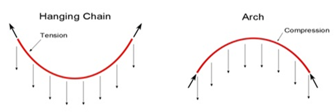 | Figure 1. Hanging chain load flow diagram |
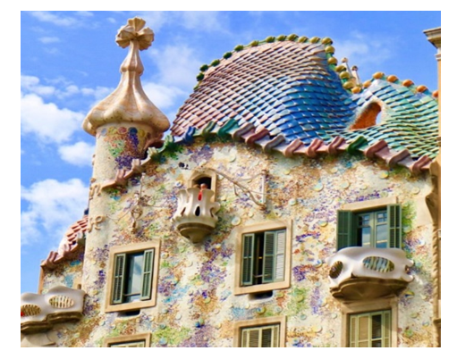 | Figure 2. Catenary roof architecture of Casa Batlló by Antonio Gaudi |
2. Research Methodology
- In this paper qualitative research method has been used. The systematic literature review has been explored through internet and secondary data from relevant published academic literature from journals articles and research papers. The data collection in the qualitative research are the data that comes from a number of case study examples that are described descriptively and are supported by illustrations and photographs to reinforce the arguments put forward. The proposed research methodology includes the Literature survey about the various studies on catenary and hanging net and the Inversion of hanging net into catenary shell. The paper will analyse and validate the research through five prominent case studies of catenary based thin ferrocement shell all around the world.
3. Literature Review
- Literature survey though refines research parameters and use of software for design and analysis; it also confirms the use of catenary form, shell and ferrocement material as economically viable and sustainable. Literature survey also points out limited application and research in catenary shells and difficulty in computational analysis of the catenary based shell. Several studies have been done in the past in shell construction designed in reinforced cement concrete (RCC) or masonry (brick), steel or timber grid. Pedreschi reviewed the work of a number of designers of the early to mid - 20th century such as Swiss engineer Robert Maillart (1930s), Pier Luigi Nervi - (1940s), Eduardo Torroja - (1940s), Felix Candela - (1950s), Heinz Isler - (1970s) and Eladio Dieste - (1980s). He also discussed that Forms based on natural laws are economical and with the use of computational methods structural design was possible for almost every kind of design. The technology could resolve whatever the designer designs [7]. Kuijvenhoven and Hoogenboom discussed a new innovative method of designing grid shells by virtue of particle spring method and simulating the behavior of a grid shell during construction. The method was fast, reliable and easy to apply, however it was possible to apply the method in a conceptual design stage only [8]. One of the researcher West introduced a new technology of concrete structures formed and designed in moulds made of high tensile fabric. Author, by citing current work and applications as well as future research opportunities, suggested a new construction method replacing rigid formwork panels with a flexible textile membrane that deflected under the dead weight of wet concrete. Steel-free concrete structures were envisioned through the use of three dimensional compression geometries formed through a simple inversion of funicular (catenary) curves [9].Van Robbroeck investigated a catenary vault. Physical working models were made to define the surface of the shell using a three-dimensional chain hanging model. The resulting shape was then scaled to match the size of the full scale version. The shell was completely un-reinforced, ultra-thin, and the resistance to loads was based on the compressive strength of the tiles. The shell was found capable of resisting the loads thus demonstrating the incredible strength of catenary shapes [10]. Wilson discussed that shells were climatically appealing and energy efficient, since their internal temperatures were known to be more evenly distributed, a welcome and important attribute for low-cost housing but this benefit, however, was only fully realized if the shell was insulated [11]. Suresh discussed the application of ferrocement material as a versatile, aesthetic and cost-effective alternative in bridging the resource gap in the scene of building construction using conventional materials. The study effectively illustrated the need for wider application of ferrocement for ensuring environmental sustainability in addition to reduction of construction costs [12]. Patidar et al studied the designing of and stabilization of arches, vaults and domes built with Compressed stabilized earth blocks (CSEB blocks) using catenary method and the funicular method [13].Pedreschi, Remo and Theodossopoulos studied studied Eladio Dieste innovative construction method for wide-span roof structures known as Gaussian vaults, their double-curved geometry was based on the catenary resulting in mainly axial compressive forces. They studied the various examples of double-curvature masonry vaults of Eladio Dieste. Dieste used brick and unlike traditional masonry vaults, they were only one brick-layer in thickness, instead of thin wide-span roofs had been built using concrete. Typically the vaults had a low rise, the span-to-rise ratio were normally 8–10 and buckling was the likely mode of failure. Dieste used the curved surface of the vaults to resist buckling and developed design procedures (post stressing with cables) to ensure their safety. Dieste formulated the critical loads of catenary arches into graphs. The method was compared with a finite-element study, which also considers the elastic deformations under self-weight, asymmetric loading owing to wind and ultimate failure owing to buckling [14].Van Mele et. al. experimented a novel form finding method for fabric formwork for concrete shells studied that concrete shells when appropriately shaped, carried loads through membrane action (i.e. axial force-only) rather than bending, which allowed them to be thin, light and elegant. There were two key aspects in the realization of thin concrete shells: 1) The determination of an appropriate shape (through a form finding process).2) The concrete shells typically had been constructed using rigid formwork regardless of the form finding method used. The variety of shell shapes that could be constructed and especially the curvature that could be achieved was limited by the shape flexibility of this formwork. This research presented a new form finding approach for the design of flexible formwork, consisting of pre-stressed structural membranes for the construction of thin, anticlastic, concrete shells [15].
4. Software Programs to Analyze Arch Bases Structures
- Tomás and Martí analyzed shape and size optimization of concrete shells. Shape optimization and stability studies were conducted by the team on shell model using ANSYS software program of finite elements [16]. Thin Shell Structure Design Tool, computational software was developed by Pendergrast to design catenary form by considering primary data structure in the cloth object. This cloth object was imagined as collection of points which are connected to each other through springs. These springs exerted forces on one another based on constants determined when the cloth was loaded [17]. Olsson used SMART Form as a tool for form finding and size optimization performance-based architecture plug-in for the 3D modeling software Rhinoceros. It combined analysis and rationalization of complex geometries with form finding and sculpting of structures, driven by a dynamic relaxation solver. The plugin transformed the 3D modelling software to a virtual physical environment, influenced by various forces and a gravitational field. It enabled sketching and sculpting of efficient compression (shells and grid-shells) and tension structures (cable nets and membranes). He studied the Implementation of beam elements and size optimization in real time form finding using dynamic relaxation [18].Nilsson in his book ‘Getting the arch back into architecture’ discussed various software programs to analyze an arch based structure [19]. The softwares selected to generate and analyze catenary based vaults were:1. VisualSFM - point clouds from photography using multi-ray photogrammetry. 2. MeshLab - A free software that had advanced tools to convert and analyze point clouds and meshes. 3. Rhinoceros 3D - This was a nurbs based (3D described by mathematical functions) and mesh (3D described by connected coordinates) modeling software for industrial and architectural design.4. Rhino Vault - This was a plug-in for Rhinoceros which used Thrust Network Analysis to generate funicular forms. These forms were accompanied with a reciprocal force polygon mapping the forces within the geometry. It was also possible to change the geometry by changing the force polygon. 5. SmartForm - Another Rhinoceros Plug-in that enabled rapid form finding using Dynamic Relaxation. 6. Scan and Solve - A plug-in that performed fast Finite Element Analysis directly on solid complex 3D geometries within Rhinoceros. 7. Grasshopper - A plug-in environment to Rhinoceros which enabled geometries within Rhinoceros to be controlled parametrically. 8. Firefly - tool within Grasshopper that acted as a bridge between Grasshopper and electronic hardware connected to the computer via USB (cable) or WLAN (wireless). 9. Kangaroo - physics engine for Grasshopper which used Dynamic Relaxation and displayed iteration results in real time. 10. Karamba - Tool for Finite Element Analysis within the Grasshopper environment. It could be combined with a genetic algorithm tool within Grasshopper in order to perform optimizations.
5. Trends in the Field of Catenary Shell Construction
- Oslo School of Architecture and Design, Oslo in the first phase, conducted experiments on interacting catenaries and based on that, brick masonry arches and vaults were made (Figure 3). The form was conceptualized by hanging chain model and finalized by digital parametric modeling [20]. Undulating wall thus made from nested catenaries was put to load tests, with different configuration of catenary arrangements and different brick laying arrangements [21]. In the second phase, design and construction of a thin shell masonry vault was done to exemplify the potential of catenary.
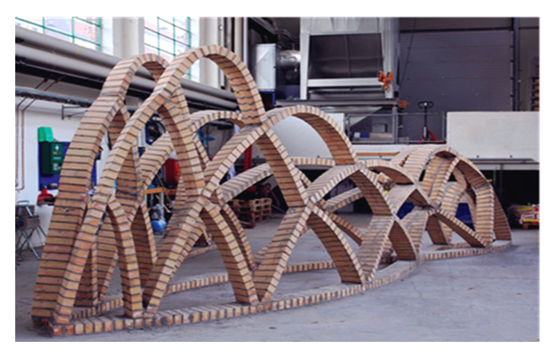 | Figure 3. A model of Nested Catenaries |
6. Ferrocement: A Novel Construction Material
- Ferro Cement (also called Ferro-concrete) is a rich or composite mortar plaster applied to both sides of a thin and well distributed reinforcement layer (usually a layer metal mesh and closely spaced thin steel rods). Normally plaster of 1:2 cement mortar should be applied to a matrix structure made of weld mesh would round the chicken mesh [29]. Ferrocement is a building material composed of a relatively thin layer of concrete, embedded with reinforcing material as steel wire mesh (Figure 4). As the building techniques are simple enough to be done by unskilled labor, ferrocement is an attractive construction method in areas where labor costs are low. Sand, cement, reinforcing material (steel rods, mesh, pipe, chicken wire, or expanded metal) and water usually can be obtained locally thus keeping the cost of construction to a minimum. There is no need for the complicated formwork of Reinforced Cement Concrete (RCC) construction or welding needed for steel construction. Everything can be done by hand and no expensive machinery is needed. Ferrocement was first discovered in 1848 in France by Joseph Lambot and patented by him in 1852. With all these qualities it seems a wonder material but due to its relatively small cross section its usage is still limited. In 1943, Pier Luigi Nervi an, Italian architect patented "ferro-cemento" and it was his use of material in his buildings that brought ferrocement as a new age material to the front. Ferrocement is extensively used for shipbuilding (Figure 5.) as a cheap replacement for steel, in housing, pipes, water tanks and decorative sculptures [30].
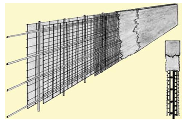 | Figure 4. A typical cross section of ferrocement panel |
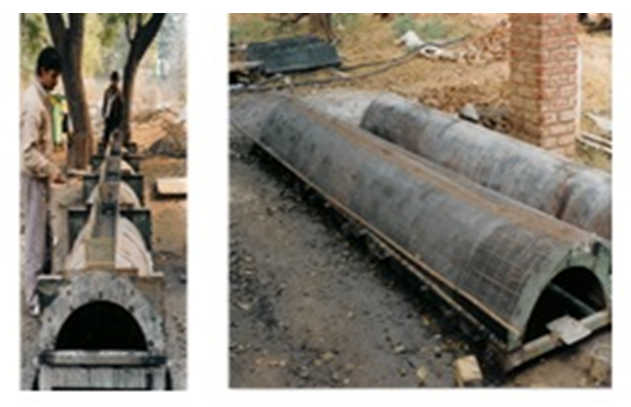 | Figure 5. Prefabrication of ferrocement shell barrel vault |
6.1. Advantages of Ferrocement
- The Ferrocement offers various advantages such as:a. It can be shaped in any form and it can take any kind of finishes on the surface.b. It can be formed into sections less than 25 mm thick and assembled over a light framework. c. The material is very dense, The structures made from it are light in weight. d. It is also rot and vermin proof, impervious to worms and borers. e. It is watertight.f. It satisfies users’ need of quality control.g. It is 45% lighter than RCC hence soil settlement cracks and earthquake risk is less. h. It uses less amount of water at site for construction.i. It is cost effective than normal construction, separate foundation, less weight, interlinked elements makes it earthquake resistant.j. Simple, efficient and time saving construction at the site.k. Lightweight, prefab, short assembling time and possibility of building up on almost any kind of soil condition.
6.2. Disadvantages of Ferrocement
- There are also few disadvantages of Ferrocement [34]. They are summarized as below:a. Excessive shrinkage due to higher cement content. Needs constant curing for a period of 7 days to avoid any shrinkage cracks.b. Structures made of it can be punctured by collision with pointed objects.c. Prone to corrosion of the reinforcing materials i.e MS bars and GI mesh due to the incomplete coverage of metal by mortar.d. As ferro-cement components are usually thin structures, Buckling is another factor that needs to be taken into consideration.e. It is difficult to fasten to Ferrocement with bolts, screws, welding and nail etc.f. Ferro-cement is labour intensive. So it might not be economical to use Ferrocement in places where the labour costs are high and large no of labors required.g. Tying rods and mesh together is especially tedious and time consuming.
7. Thin Shell Structure: Case Studies
- The basic motive of both architects and engineers over the centuries has been to achieve column free covering over a large area using less and less material. The free spanning shell structures made were heavy vaults and domes of roman Gothic era to extremely thin concrete shells and filigree space structures of twentieth century. Thin shells were revolutionized by Architect Pier Luigi Nervi, Euro Saarinen and Felix Candela [35]. The shell structures are classified as single curved or doubly curved and synclastic or anticlastic. A grid shell though scarce due to their complex form finding process, is of utmost importance in this research as they are formed by catenaries [36]. Thin shells have been constructed of reinforced cement concrete, timber and steel but there are no examples of catenary based ferrocement thin shell. This research will document and try to prove that catenary based ferrocement shells are the future in terms of economy and in reducing carbon imprint.
7.1. The Pantheon, Rome, Italy
- The Pantheon is a former Roman temple in Rome, Italy. It was built by the emperor Hadrian almost 2,000 years ago. The building is cylindrical with a portico of large granite Corinthian columns (eight in the first rank and two groups of four behind) under a pediment. A rectangular vestibule links the porch to the rotunda, which is under a coffered concrete dome, with a central opening (oculus) to the sky (Figure 6). Almost two thousand years after it was built, the Pantheon's dome is still the world's largest unreinforced concrete dome. The height to the oculus and the diameter of the interior circle are the same, 43 metres. The 4,535-tonne weight of the Roman concrete dome is concentrated on a ring of voussoirs 9.1 metres in diameter that form the oculus, while the downward thrust of the dome is carried by eight barrel vaults in the 6.4-metre-thick drum wall into eight piers.
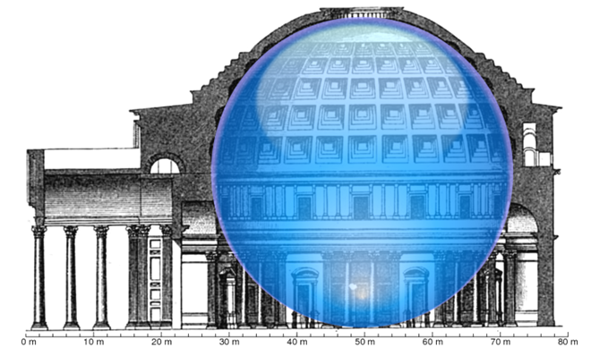 | Figure 6. Cross-section of the Pantheon showing a 43.3 m diameter sphere fits under its dome. 150A.D |
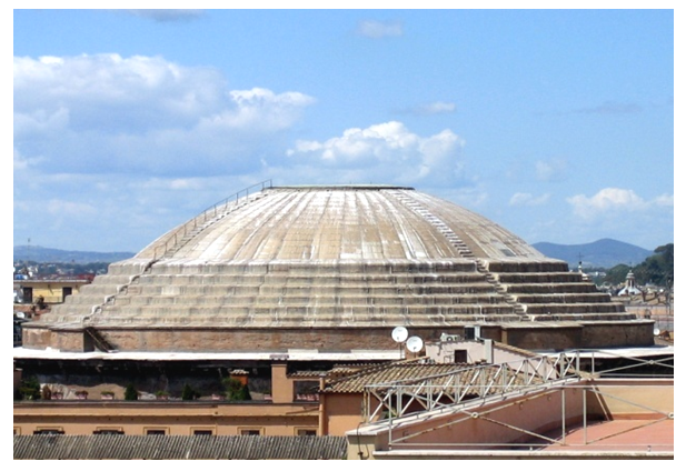 | Figure 7. The exterior of Pantheon's shell dome |
7.2. TWA Flight Center, New York, USA
- TWA Flight Center, also known as the Trans World Flight Center, was an airport terminal at New York City's John F. Kennedy International Airport (JFK). The TWA Flight Center, designed by Eero Saarinen is a pioneering example of thin-shell construction, consisting of a reinforced concrete shell roof supported at the corners. It is located at the middle of a curve in one of JFK Airport's service roads, in front of the elevated Air Train JFK people mover. Saarinen collaborated with Charles S. Whitney and Boyd G. Anderson of the firm Ammann & Whitney to structurally engineer the roof. The TWA Flight Center is a two-story structure. The roof's thin concrete shell was built to span a space with a minimum of material. The roof is composed of four concrete shells: two upward-slanting shells at the edges, which resemble wings, and two smaller shells slanting downward toward the front and back of the structure (Figure 8). The upward-slanting shells reach a height of up to 23 m above the ground level. The rooftop shells converge at the center of the roof, where each of the four shells supports the others. Four "Y"-shaped piers support the roof, facing the front and back facades. Skylights are located within the gaps between each shell. The building's main entrance is on the land side, where the roof projects over a sidewalk (formerly a driveway) with a scupper. The roof concrete varies in thickness from 180 mm at the edges to 1,000 mm at the convergence of the four shells. The roof weighs 6,000 short tons (5,400 t) in total [38].
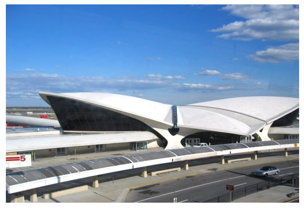 | Figure 8. The four concrete shells of TWA Flight Center, New York |
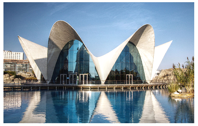
7.3. L'Oceanogràfic, Valencia, Spain
- The Oceanographic is an oceanarium situated in Valencia, Spain, where different marine habitats are represented. The steel-fiber reinforced concrete thin-shell structure was designed by the architect Félix Candela and the structural engineers Alberto Domingo and Carlos Lázaro (Figure 9). The shell structure has a distinctive hyperbolic parabola shape of the roof [39]. It is integrated inside the cultural complex known as the Ciutat de les Arts i de les Ciències (City of Arts and Sciences).
 | Figure 9. Hyperbolic Paraboloid shell of L'Oceanogràfic, Valencia, Spain |
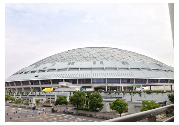
7.4. The Nagoya Dome, Nagoya, Japan
- The Nagoya Dome constructed in 1997, is a baseball field, located in the city of Nagoya, Japan. The dome has the capacity to seat up to 40,500 for sports and 49,000 for concerts. It is an example of a geodesic dome. This is the world's largest dome with a single-layered lattice structure. The roof frame is expressed as the interior structure design (Figure 10). The top of the roof features a shading system that allows the adjustment of natural light according to purpose. The roof structure incorporates a single-layered lattice, comprising triangular frameworks of steel pipes with a diameter of 65 centimeters and a length of ten meters. This structure means that the roof has become thinner, reducing its dominating impression on the periphery [40].
 | Figure 10. Single layered lattice shell roof of Nagoya Dome, Nagoya |
7.5. Ingalls Rink, Connecticut, USA
- David S. Ingalls Rink is a hockey rink in New Haven, Connecticut, designed by architect Eero Saarinen and built between 1953 and 1958 for Yale University. It is commonly referred to as The Whale, due to its shape (Figure 11). The building was constructed for $1.5 million, which was double its original cost estimate. It seats 3,500 people and has a maximum ceiling height of 23 meters. The building is named for David S. Ingalls, Yale class of 1920, and David S. Ingalls, Jr., Yale class of 1956, both of whom were hockey captains. The building was included on the America's Favorite Architecture list, created in 2007 by the American Institute of Architects [41].
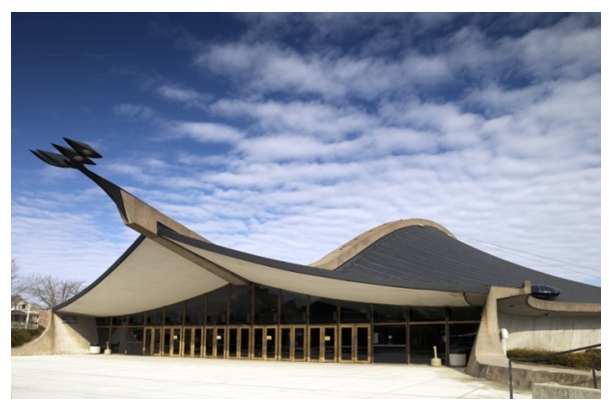 | Figure 11. The thin shell roof of Ingall’s rink, Connecticut, USA |
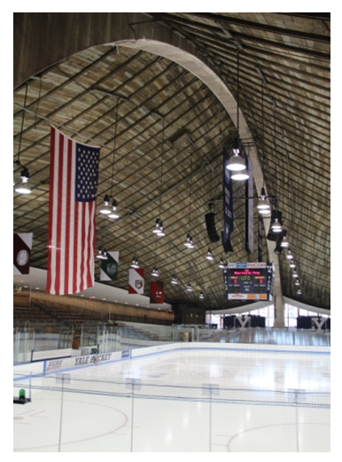 | Figure 12. Catenary shaped concrete arch dominates the interior |
7.6. Kresge Auditorium, Massachusetts, USA
- Kresge Auditorium (MIT Building W16) is an auditorium structure at the Massachusetts Institute of Technology, located at 48 Massachusetts Avenue, Cambridge, Massachusetts. It was designed by the Finnish-American architect Eero Saarinen, with ground-breaking in 1953 and dedication in 1955. The auditorium is defined by an elegant thin-shell structure of reinforced concrete, one-eighth of a sphere rising to a height of 15 m, and sliced away by sheer glass curtain walls so that it comes to earth on only three points (Figure 13). Thin-shelled concrete technology was innovative for the times; the dome is proportionately thinner than an eggshell. The dome weighs only 1,200 tons and it is clad with copper. It was originally covered with smooth, bright orastone which was then replaced with lead sheeting attached with stainless steel wires. The dome was originally supported only at the three corners, In 1980, cracks were found in the structure and the auditorium was closed immediately for repairs. Copper replaced the lead at that time, and the walls now carry part of the roof load. Sitting on a circular red brick platform, the dome contains a concert hall (with seating for 1,226 people), plus a lower level that houses a small theater of seating 177 persons, two rehearsal rooms, dressing rooms, offices, bathrooms, and lounges [42].
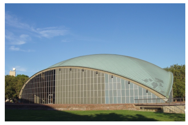 | Figure 13. The thin shell roof of Kresge Auditorium, Massachusetts, USA |
8. Discussion and Conclusions
- The paper basically reviews the technological development of catenary based ferrocement shells, and showed that catenary as a form in designing of structure has been in vogue since centuries but its form finding process has been empirical. A unique insight into this very innovative form has been provided by history as well as by present day construction techniques. This research has presented the history, properties and application of catenary shells and thin ferrocement structures. The basic concepts of catenary based ferrocement shell have been studied. The form was deduced by hanging chain method whereas current research is bringing computational methods and parametric design methods to fore. These methods are being validated by cross analyzing empirical designs with computational designs. Ferrocement as a material has been thoroughly investigated and current research is moving towards strengthening of the material by use of different additives. These additives are glass fibers, plastic fibers, brass coated steel fibers or even nanoparticles. The research could find application in low cost, low rise structures and to investigate any strategic advantage offered by catenary based ferrocement thin shells. The material, ferrocement today exists as a sustainable and ecofriendly material acting as a challenge and research area for designers. The paper emphasized the reason for catenary shells as a ‘form’ and ferrocement as a ‘material’ combined together could provide economically viable and sustainable solutions to buildings and structures.