Rasool Heydari1, Arash Totonchi2, Zahra Ebrahimi3
1Student Civil Engineering, Civil Dept, Apadana Nonprofit Shiraz
2Assistant Professor, Civil Dept, Islamic Azad University, Marvdasht Branch, Iran
3Msc in Structural Engineering, Civil Dept, Shiraz University, Shiraz, Fars, Iran
Correspondence to: Rasool Heydari, Student Civil Engineering, Civil Dept, Apadana Nonprofit Shiraz.
| Email: |  |
Copyright © 2017 Scientific & Academic Publishing. All Rights Reserved.
This work is licensed under the Creative Commons Attribution International License (CC BY).
http://creativecommons.org/licenses/by/4.0/

Abstract
In recent decades, some of the limitations of space and economic, political and military considerations attracted the attention of developed and developing countries with the construction of underground structures for the purpose of construction, mining and military. In this context, many studies took place in order to understand the behavior of underground structures against blast waves. Generally, underground structures are more resistant than structures on the ground to the blast; hence, they show less changes and degradation with explosion. This study aims to schematically modeling the underground structures by using ANSYS software and investigate the effect of soil type and the distance from the explosion site on design criteria including, moment, axial force, shear force and curvature. The results of simulations show that the explosive behavior is vastly different in each soil types ranging from soft to hard. All values of the evaluation criteria decrease with distance from the center of the explosion.
Keywords:
Underground concrete structure, Blast load, ANSYS schematic modeling, Soil type, Structure design criteria
Cite this paper: Rasool Heydari, Arash Totonchi, Zahra Ebrahimi, Effect of the Type of Soil on the Design Criteria of Horseshoe Shape Concrete Structures under the Surface Blast, Architecture Research, Vol. 7 No. 5, 2017, pp. 201-211. doi: 10.5923/j.arch.20170705.02.
1. Introduction
One of the strategic objectives in the security, throughout the world is blast and explosion, and for this reason, finding resources that will directly represent any information about it, is almost impossible. Hence, there is an obligation to carry out this research to study the effect of soil type and the distance from explosion on the mechanical behavior of structures buried underground.
1.1. Explosion
Blast effects are waves which expand from explosive material into the air with high-intensity. When the wave expands, its ability (power), duration and velocity is decreased. When the wave expands in the air, it collides with the structures that are in its path and bounces structures surrounded by waves. The size and distribution of the explosive charge on the structures are function of: 1) characteristics of explosives, material type, free energy, mass of explosives. 2) The location of explosion over protective structures. 3) Size and compression strength with the ground or the structure [1-2]. In the meantime, the impact of barriers on the positive and negative phases is different. Positive peak pressures decrease much faster than the negative pressure. This difference is due to the fast increase in blast load which is caused by high frequencies and short wave lines [3]. Since most obstacles are large, compared to the wavelengths, resulting explosion peak pressure would decrease significantly. If the explosion disseminate in direct tunnels, corridors and trenches, only a small amount of pressure is reduced, which in this case is still destructive [4].
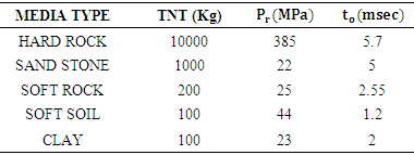
1.2. TNT Equivalent
TNT equivalent is used to determine the amount of energy released in the explosion. In Table 1 equivalent TNT for variable explosions is represented [5]. In order to simplify the calculations in some cases, equation of time - positive phase pressure is presented with the triangular pulse for a period of it (Figure 1). This approximation is used to determine the maximum reaction after crossing pressure pulse in the structures. In this case, the total impact on the triangular pulse curve, abc, must be equal to the impact of real time – pressure curve [6].Table 1. TNT Content equivalents
 |
| |
|
Table 2. PPV threshold for underground structures
 |
| |
|
 | Figure 1. History of Time pressure blast wave at one point |
1.3. Explosion and Buried Structures
In general, the impact to the ground as a result of a bomb explosion on or near the ground and buried structures is a major risk on the structures. Stresses caused by the buried explosions are larger in size and have more time frequency than the explosion in air [7, 8]. Significant increase tensions and earthmoving occur when the bombs penetrate more in the ground before they explode. Important variables that affect the intensity of the explosive charge include:1) Size and distance of bombs from constructs 2) Mechanical properties of soil or rock between the construct and explosion site3) Depth that bombs penetrated into the ground at the time of the explosion (blast depth) [9, 10].With these factors, the effect of rock or soil properties on hitting the ground is rarely predicted by simple methods. Hence, the Intensity of hitting the ground for a wide range of changes in soil type may increase more (e.g. low intensity in the dry sand compared to the saturated clay) [11].There are two important things that should be considered in evaluating the risk of hitting the ground on buried structures:1) The bomb that explodes directly on top of the building (facing on top or in the protective structure or cover rocks), causing a direct load on the roof slab.2) The bomb that penetrates into the soil around the structure and explodes near the structure, would insert load on the structure’s wall and ceiling.
1.4. Soil Impact on the Explosion Load
As noted before, the soil type has an important role in the design and deterioration of structures. Soil has an important role in impact resistance of buried structures in the explosion. Soil good performance in this area is due to its immobility, ability to scatter forces, the ability of energy dissipation in plastic deformation as well as its camouflage ability. Transferring the structure to the underground can significantly increase it’s withstand to a blast, however, can bring new forces and destruction [11, 13].Several important concepts should be considered when designing dynamic building against explosions. These include loading, energy absorption, safety factor, resistance functions, structural and functional considerations and most importantly, the factor of uncertainty.
1.5. Design Approach TM 5-855-1
This design approach suggests a way in which the process can be used to design a single member such as a ceiling or side wall structure. Then by repeating the process for each component of the structure, the entire structure can be developed. This design approach is based on the use of simple equations and diagrams. This process is divided into three main sections: (1) determine the free field loads. (2) The calculation of structural loads and (3) predict the structural response [4, 15]. The explosive tests carried out in soils ranging from sand to clay saturated dry and loose, and the empirical correlations have been proposed. The empirical relationships used to calculate the stresses and velocities of free field in the given range of investment under explosive charges in different soil types. The elastic modulus and Poisson estimates for different soils are derived from these existing sources [16].
1.6. Controlling the Dusty Environment around the Structures in Terms of PPV
Safety and stability of underground structures and vibration damage resulting from the explosion is often affected. The Source of accidental explosions could be blasting, drilling or military weapons. Accurate assessment of the damage in rock mass under the effect of the explosive charge blast is the first step to estimate the stability of underground structure. The amount of damage depending on the distance to the source of the explosion, the weight of the explosive, properties of the rock mass and the distribution of fractures in the rock mass. Some field tests were conducted and the test data and results were recorded. Empirical failure criteria, usually based on peak particle velocity (PPV), were obtained from observations and measurements [17]. According to papers, presented PPV threshold for failure-free mode is quite different, because the quality of monolith and mass rocks varies from place to place [18].Given the importance of the issue, the aim of this study is to evaluate the effect of the soil type under the blast and the distance from explosion, and measuring parameters such as deformation, stress, strain and maximum particle rate. Finally, using the results could be use full in designing the underground structures under the surface explosions.
2. Materials and Method
2.1. Software Designing
ANSYS was used to model a software system because of its special capabilities. In Order to avoid excessive complexity in analysis of the software, linear models were used for soil. Figure 2.a, 2.b and 2.c represent the outline of the buried structure, ANSYS simulation and the design structure respectively. | Figure 2.a. The buried structure outline |
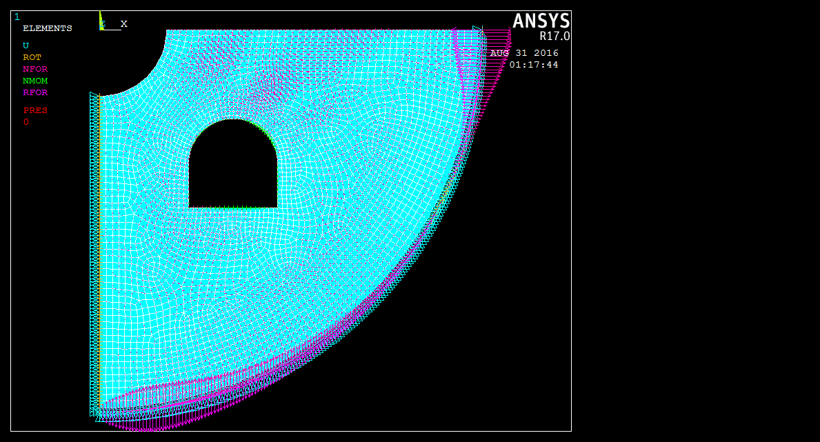 | Figure 2.b. ANSYS simulation of the model |
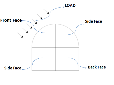 | Figure 2.c. Design structure |
To perform the analysis, behavioral models which are close to the reality are used. It should also be noted that for analysis on axially symmetric model, the value of materials in the model will be used.
2.1.1. Behavioral Half -Space Model, Ax Symmetric Model
The most important advantage of the model geometry is its symmetric orientation that helps it to provide a two-dimensional ax symmetric model with fewer elements compared to the complex three-dimensional model. Using an ax symmetric model decrease the hardware memory needed to solve the problem and favorably save time [1, 2]. According to modeling a limited part of the half-space environment around the site of the explosion in direct solution method, shifting boundaries are used In order to inhibit the wave reflection and absorption of model. The inner damping capacity of environment border is not able to remove waves returning from the boundaries, and this causes the wave energy trapped in these environments and affects the results. Therefore, the use of absorbent boundaries in this model and the selection of parameters must be considered carefully. For this purpose, the adsorbent transitional border is used. In the lateral boundaries of the medium, in each node, the two orthogonal damper spring elements in two directions perpendicular to each other is used with the Combine14 element to absorb the waves and prevent their reflection. Spring stiffness and damper coefficients were calculated from the following formula:The term E is the modulus of elasticity, ρ is density of the medium, L the length of the absorbed border, Vρ wave speed in the medium and α = 2 in symmetrical axis medias [3].Here, in order to model the soil, the eight-node element, Plane183, is used. This element is an element mesh generator suitable for two-dimensional structures with curved boundaries. It also has the ability to analyze linear and nonlinear problems [4]. Shell208 used to model the structure of the element. This element is suitable for symmetric lattice shell structures. It has 2 nodes and each node has two degrees of freedom.
2.1.2. Initial Model Controlling to Assess the Adequacy of the Soil Environment
For the control of soil environment, different models with different radians of soil environment prepared and analyzed. Absorbent boundaries set to optimal performance, hence, returned waves were eliminated. These elements as well as axially symmetric planar elements used, has eight nodes, each node has two degrees of freedom (movement in horizontal and vertical directions). By trying these two numbers a specific radius would be obtained. This radius simulates every parameter such as stress and strain close to one thirtieth of their quantity nearby the explosion. By doing the above steps can be expected that performing dynamic analysis has been prepared under the force of the blast impact (Ebrahimi model [5]).
2.1.3. The Basic Controller Model to Assess the Adequacy of the Load
This criterion is used for TNT explosive charge that imposed on the structure. This criterion is based on the soil capacity in terms of strain and the mass of applied TNT to the environment. This would control the maximum strain on the environment to stand in a range of capacity of the soil. By trial and error of different masses due to the strain of explosives in different environments suitable for loading on different soils, desirable results would be obtained (Ebrahimi model [5]).
2.1.4. Loading Blast
The simulation for underground structures of concrete with compressive strength, the criterion of 30 MPa and the grade of 400 kg per cubic meter was used. Loading pattern as a form of time plan was applied on the upper parts of the blast holes. A sensitivity analysis was performed for three important parameters: 1) Meshing elements, 2) time range and 3) the distance from absorbing boundary. The purpose of this analysis is to obtain the most optimal network size, time and distance from the border absorbent which for this analysis is less than 5% error rate in environment responses.
3. Results and Discussion
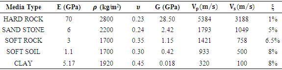
In this section the results and analysis of the impact on the soil type and the load parameter on the structures will be discussed. As mentioned before, the input parameters include fixed and variable parameters. Fixed parameters related to structural parameters such as Young's modulus (E), shear modulus (G), Poisson's ratio (υ), mass density (ρ) and damping (ξ) as well as the parameters are loading pressure and load duration. Variable parameters represented as soil hardness, soil types and the distance from the explosion.
3.1. The Basic Controller Model to Assess the Adequacy of the Soil Environment
For controlling the soil environment, different models with different radians prepared and analyzed. Results shows that the Absorbent boundaries had quite optimal performance and could eliminate returned waves. To calculate the distance of the boundary two criteria are considered: a standard distance 10 times of the loading cavity radius and other criteria 4 times the wavelength of the environment. According to the results presented in Table 3, it is clearly seen that at the time of loading, the response of structures not observed. But after a few hundredths of a second, structures were damaged by the deformations and stress force. To determine the parameters of the load on each of the environments, the UFC Regulation graph was used [1].Table 3. Loading parameters in different environment
 |
| |
|
3.2. Sensitivity Analysis
The sensitivity analysis was performed for three important parameters: 1) Meshing elements, 2) time range and 3) the distance from the absorbing boundary. Meshing sensitivity for systems with specific dimensions was performed, then these dimensions were repeated several times in one-half and double quantities. Some system responses such as speed and tension were determined in some points. In all analyzes, the values were compared with each other and the error rate was determined. The largest network dimensions for which the error was less than 5%, was considered as a criteria. In order to estimate the time sensitivity the analysis time was divided into intervals and each of the periods repeated with twice and half amounts.In this part of the analysis, the stated parameters will be discussed. As mentioned earlier, input parameters were fixed and variable parameters. Fixed parameters related to structural parameters such as Young's modulus (E), shear modulus (G), Poisson's ratio (υ), mass density (ρ) and damping (ξ) as well as the parameters are loading pressure and load duration.
3.3. PPV
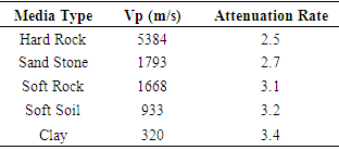
The variable Parameter related to soil type is completely presented in Table 4. Concrete structures with thickness of 30 cm, in different environments with PPV which was under the influence of different soil environments were studied. PPV change rate of the variable soil is shown in Figure 3. In Table 5 The rate of deceleration peak values are given for five environments. The results indicate that, the maximum speed of particle in the front face of the explosion decreases with increasing the distance from the explosion center. The rate of decline was Variant in different environments. Results in Table 5 shows that the highest drop rate belongs to the environment with the softest clay and the environment with the hard rock has the lowest rate of decline.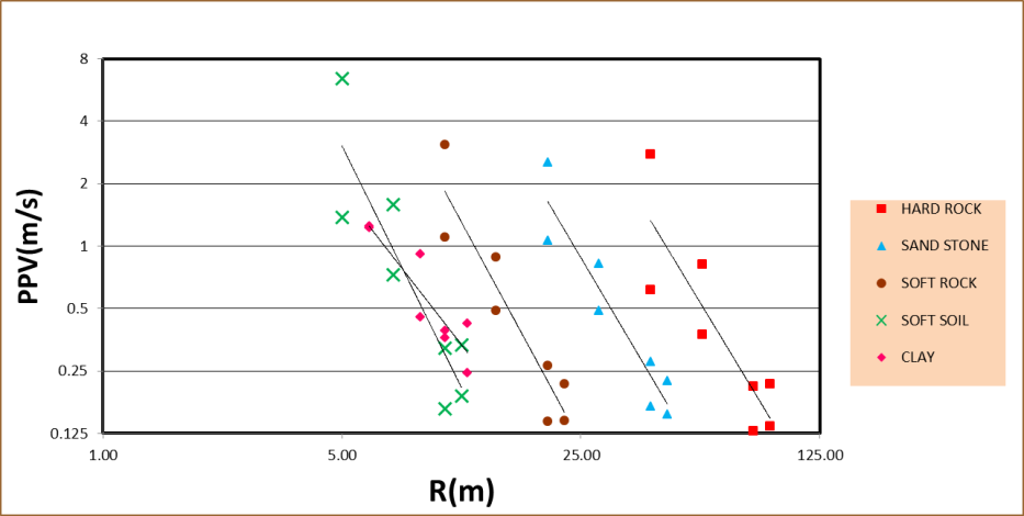 | Figure 3. PPV changes in different environments-thickness 30 cm –Front face load |
3.4. The Maximum Strain around the Concrete Structure
In this section the main changes to the normal strains and shear strain ε1 and ε2 is studied. Concrete structures at three faces, the front, side and behind were investigated and results are presented separately for each side. According to Figure 4, it could be concluded that the main shear strain in the front face to the blast decrease with increasing the distance of structure from the explosion center. The harder the environment is the less will be the main shear strain.Table 4. Mechanical Characteristics of clay
 |
| |
|
Table 5. PPV changes in different environments-thickness 30 (cm)- front face load
 |
| |
|
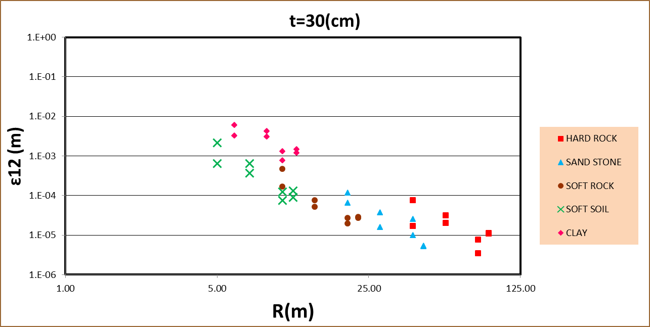 | Figure 4. The main shear strain changes in different environments-thickness 30cm- front face load |
3.5. The Maximum Concrete Structure’s Moment
In this section, the positive and negative moment changes in vertical and horizontal directions due to the surrounding soil type, is investigated on the buried concrete structure. The concrete structure at three faces, including the front, Side and behind the load is studied and results are presented separately for each side. Figure 5.a and 5.b show changes in positive and negative horizontal moment in concrete structures with 30 cm thickness.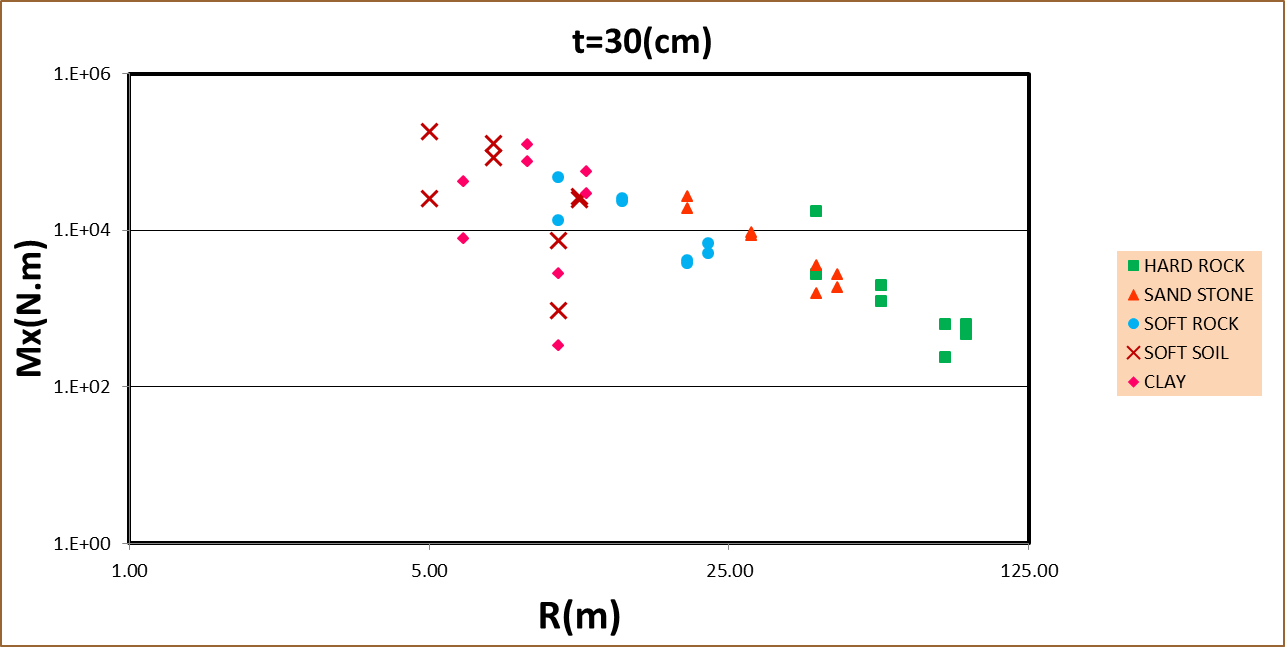 | Figure 5.a. Changes in the positive horizontal moment in different environments-thickness 30 (cm) – front face load |
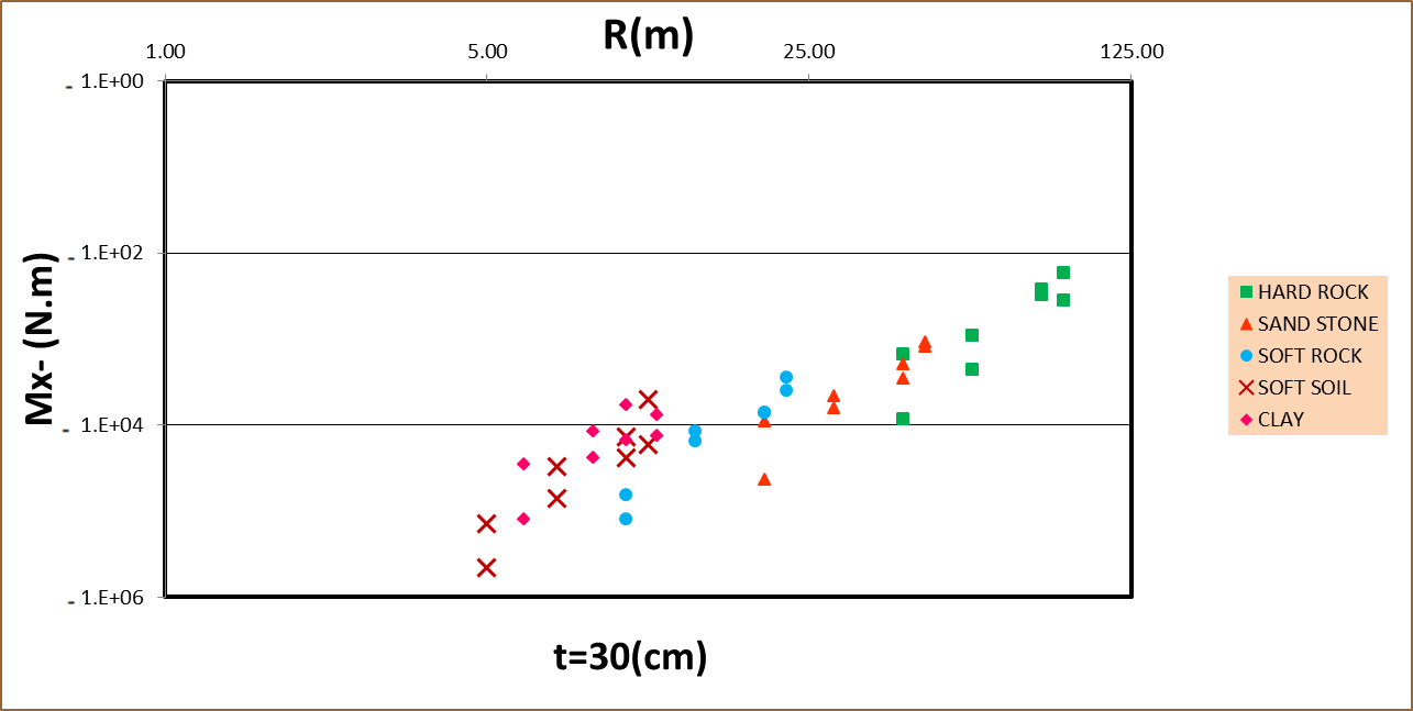 | Figure 5.b. Changes in the negative horizontal moment in different environments-thickness 30 (cm) - front face load |
As it could be seen, the trend of negative moment bolt in horizontal structures has an increasing trend from soft soil to harder than regular soil. Moreover, the horizontal positive moment changes have a decreasing trend from soft to hard mixture.Figures 6.a and 6.b Shows moment changes in positive and negative vertical concrete structure with a thickness of 30 cm, in different environments in front face. As is known, positive and negative moments in the horizontal and vertical decrease with increasing the distance from the explosion center. The harder the environment is, horizontal a vertical positive / negative moments would be less.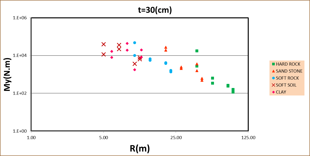 | Figure 6.a. Changes in positive vertical moment in different environments-thickness 30 cm- front face load |
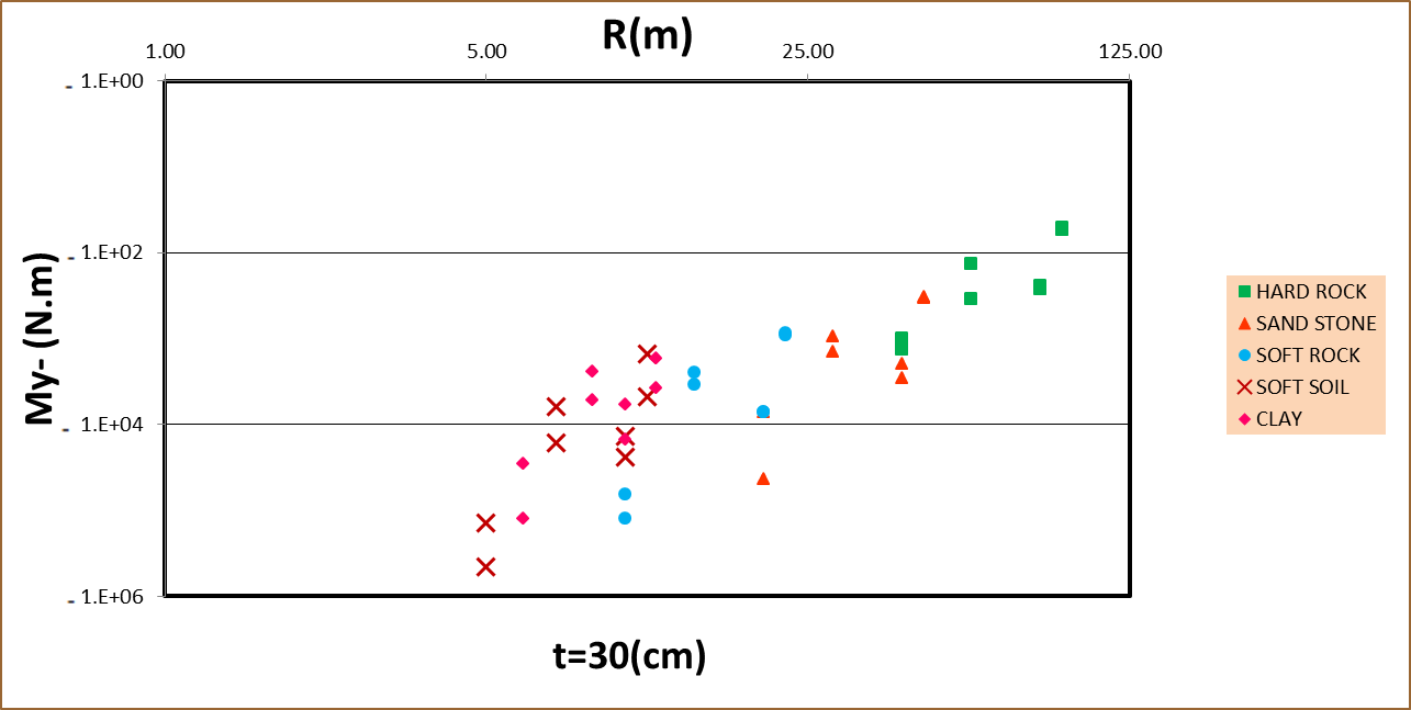 | Figure 6.b. Changes in negative vertical moment in different environments-thickness 30 (cm) - front face load |
3.6. Horizontal Positive Axial Forces in Different Environments
The changes in axial forces, compared to the environment surrounding the concrete structure, were studied. Concrete structures were studied at three faces, the front, and side and behind the load and the results were presented separately for each side. Figures 7.a and 7.b, shows the positive and negative axial forces in horizontal concrete structure with a thickness of 30 cm, in different environment in front face mode.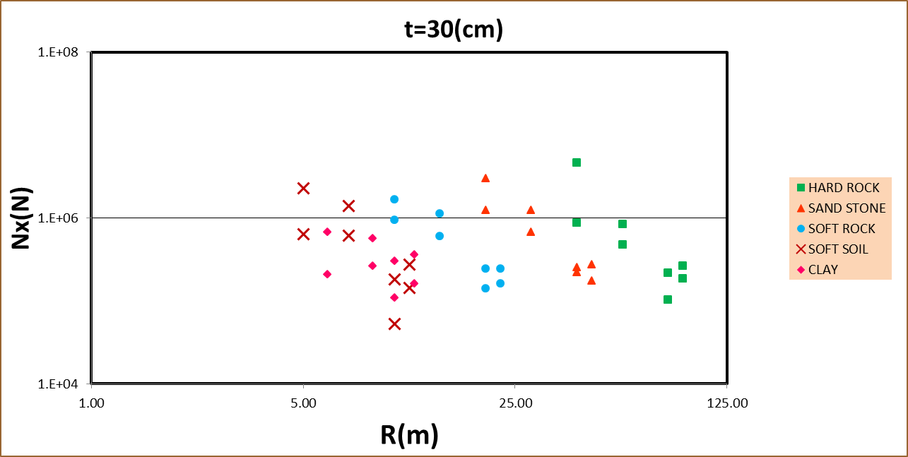 | Figure 7.a. Positive axial forces in horizontal concrete structure with a thickness of 30 cm, in different environment in front face mode |
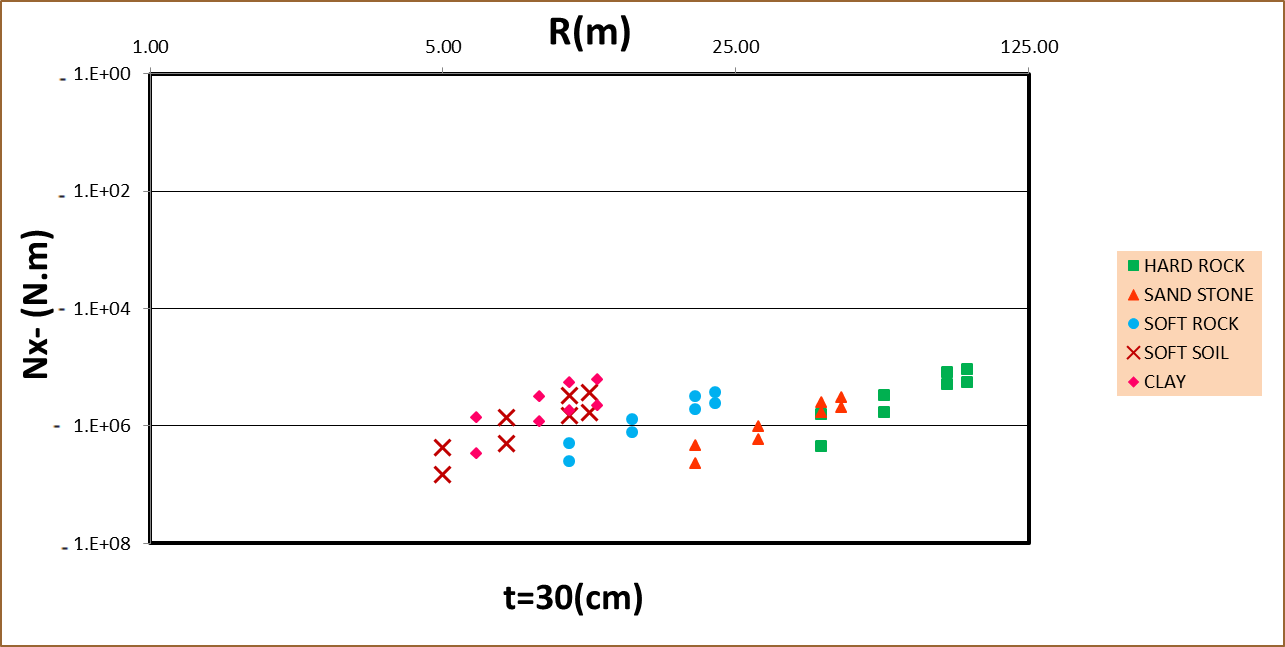 | Figure 7.b. Negative axial forces in horizontal concrete structure with a thickness of 30 cm, in different environment in front face mode |
Figure 8.a and 8.b shows changes of positive and negative axial forces acting in vertical concrete structures with thickness of 30 cm, in different environments-front face.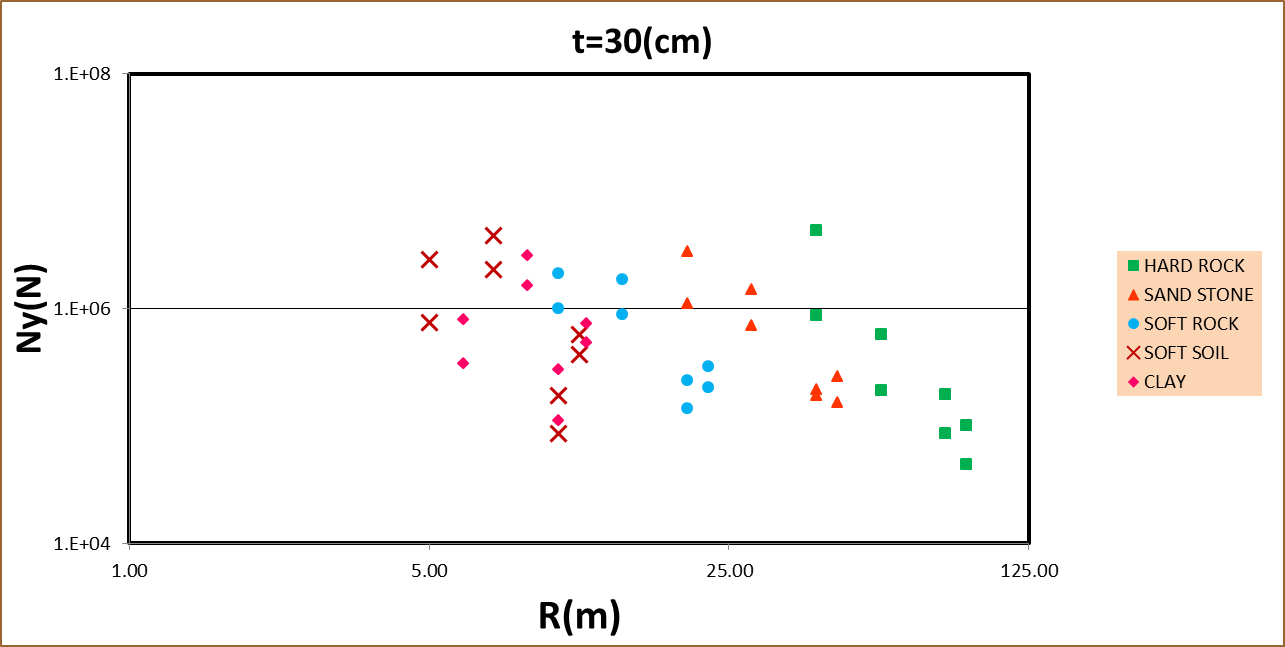 | Figure 8.a. Positive vertical axial forces in different environments-thickness 30 (cm) front face load |
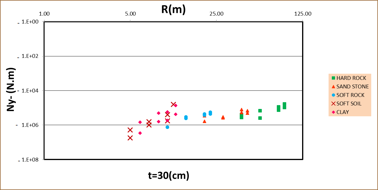 | Figure 8.b. Negative vertical axial forces in different environments-thickness 30 (cm) - front face load |
The results indicate the fact that the horizontal and vertical axial forces in both positive and negative aspects of the blast decrease by increasing the distance of the buried structure from an explosion center. The harder the environment is, positive / negative forces in horizontal and vertical axis would be less.
3.7. Shear Force Changes in Different Environments
In this section shear force changes in concrete structures for different type of soil is studied. Figure 9 shows changes in shear forces in the concrete structure with a thickness of 30 cm.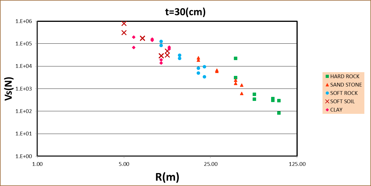 | Figure 9. The shear force changes in different environments-thickness 30 (cm) – front face load |
As is known, shear forces in the front face decrease with increasing the distance from the explosion center. The harder the environment is, these shear forces would be less.
3.8. Curvature Force Changes in Different Environments
In figure 10.a and 10.b, horizontal and vertical curvature changes in concrete structures with thickness of 30 cm, in different environments for the front face to the load is shown.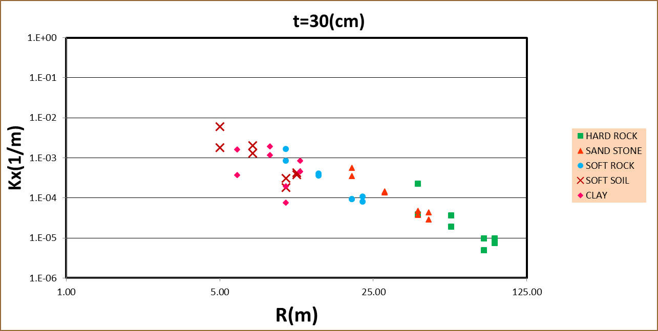 | Figure 10.a. The horizontal curvature change in various environments- thickness 30 (cm) front face load |
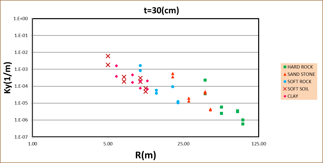 | Figure 10.b. The vertical curvature change in various environments- thickness 30 (cm) -front face load |
Horizontal and vertical curves in front face to the load decrease by increasing the distance between the buried structure and explosion center, and the harder the environment is, horizontal and vertical curvatures would be less.
4. Conclusions
The results of the study show that the behavior of elastic medium is a function of numerous parameters and geometric properties of materials. Additionally, this behavior will affect the explosion characteristics. The amount ant the intensity of effective parameters change in different situations makes any model more complex. Hence, in this study, by creating a theoretical model and provide a database with finite element, modeling such complex conditions is possible. The database can be used to build an experimental model which in turn is very effective to predict the behavior of structure and its surrounding environment in different situations. In the present study, the aim was schematic modeling of underground structures using ANSYS to form a buried cavity, as well as the effect of soil types on concrete structures and underground engineering design criteria includes moment, axial force, shear force and curvature of the surface explosion revealed.
References
| [1] | Bangash, M. and T. Bangash, Blast and Explosive Loadings on Buildings. Explosion-Resistant Buildings: Design, Analysis, and Case Studies, 2006: p. 67-101. |
| [2] | Jayasinghe, L.B., et al., Blast response of reinforced concrete pile using fully coupled computer simulation techniques. Computers & Structures, 2014. 135: p. 40-49. |
| [3] | Olarewaju, A.J., Prediction and assessment of loads from various accidental explosions for simulating the response of underground structures using finite element method. Electron. J. Geotech. Eng, 2013. 18: p. 375-396. |
| [4] | Ngo, T., et al., Blast loading and blast effects on structures–an overview. Electronic Journal of Structural Engineering, 2007. 7: p. 76-91. |
| [5] | Bastea, S., et al., CHEETAH 5.0 User’s Manual. Lawrence Livermore National Laboratory, 2007. |
| [6] | Zehrt Jr, W.H. and P.F. Acosta. Revision of Army Technical Manual 5-1300/NAVFAC P-397/AFR 88-22, “Structures to Resist the Effects of Accidental Explosions”. in Metropolis and Beyond. 2005. |
| [7] | Jayasinghe, L.B., et al. Blast induced ground shock effects on pile foundations. in Proceedings of World Academy of Science, Engineering and Technology. 2013: World Academy of Science, Engineering and Technology (WASET). |
| [8] | Roller, C., et al., Residual load capacity of exposed and hardened concrete columns under explosion loads. Engineering Structures, 2013. 55: p. 66-72. |
| [9] | Bulson, P.S., Explosive loading of engineering structures. 2002: CRC Press. |
| [10] | Liu, H., Dynamic analysis of subway structures under blast loading. Geotechnical and Geological Engineering, 2009. 27(6): p. 699-711. |
| [11] | Jayasinghe, L.B., et al., Effect of soil properties on the response of pile to underground explosion. Structural Engineering International, 2014. 24(3): p. 361-370. |
| [12] | Roy, P.P., Rock blasting: effects and operations. 2005: CRC Press. |
| [13] | Fiserova, D., Numerical analysis of buried mine explosions with emphasis on effect of soil properties on loading. 2006. |
| [14] | Edri, I., et al., On blast pressure analysis due to a partially confined explosion: I. Experimental studies. International Journal of Protective Structures, 2011. 2(1): p. 1-20. |
| [15] | Hyde, D.W., User's Guide for Microcomputer Programs ConWep and FunPro, Applications of TM 5-855-1, "Fundamentals of Protective Design for Conventional Weapons". 1988: US Army Engineer Waterways Experiment Station. |
| [16] | Coduto, D.P., Foundation design: principles and practices. 2015: Pearson. |
| [17] | Gohl, W., et al., Explosive compaction: design, implementation and effectiveness. 2000. |
| [18] | Singh, P., et al., Blast vibration effects in an underground mine caused by open-pit mining. International Journal of Rock Mechanics and Mining Sciences, 2015. 80: p. 79-88. |
| [19] | Li, Z. and H. Huang. The calculation of stability of tunnels under the effects of seismic wave of explosions. in Proceedings of the 26th Department of Defence Explosives Safety Seminar, USA, Department of Defence Explosives Safety Board. 1994. |

 Abstract
 Reference
 Full-Text PDF
 Full-text HTML