Alfredo Esteves1, 2, M. Victoria Mercado2, Carolina Ganem2, Daniel Gelardi1
1Facultad de Arquitectura, Urbanismo y Diseño, FAUD - Universidad de Mendoza, Boulogne Sur Mer, Mendoza, Argentina
2Instituto de Ambiente, Habitat y Energía, INAHE – CCT – CONICET, Mendoza. Av. Ruiz Leal s/n, Mendoza, Argentina
Correspondence to: Alfredo Esteves, Facultad de Arquitectura, Urbanismo y Diseño, FAUD - Universidad de Mendoza, Boulogne Sur Mer, Mendoza, Argentina.
| Email: |  |
Copyright © 2017 Scientific & Academic Publishing. All Rights Reserved.
This work is licensed under the Creative Commons Attribution International License (CC BY).
http://creativecommons.org/licenses/by/4.0/

Abstract
The amount of energy storage strongly depends on the position, material and it thickness. In this paper, the geometric and energetic positioning of thermal mass has been studied in order to determine the most convenient locations. Following this, 14 cases representing different positions of windows within facades facing the Equator are analyzed. These cases are studied with a model that estimates direct solar radiation that crosses through the window and is absorbed in various surfaces within the room. All cases show that 70% to 90% of the direct daily solar radiation that is transmitted by vertical windows impact the floor during the most energetic hours (from 9am to 3pm – solar time). East or Sest facades receive only 0% to 13% depending on whether the window is near the side East or West of the façade. The southern wall receives up to 10% of daily direct solar radiation depending on the depth of the room and the height of the window. Optimal thicknesses of storage materials are studied through the diurnal heat capacity (dhc), which also depends on the material and solar insolation of the elements. If it is sunny, optimal thickness and dhc are: 0.20 m and 266.1 kJ/m2.°C for granite; 0,20 and 247.3 kJ/m2.°C for concrete; 0,15 m and 224 kJ/m2.°C for paver brick and for hardwood 0,075 m and 49.8 kJ/m2.°C. In remote areas that do not receive direct sunlight, the optimum thickness of walls is reduced to 0,075 m with dhc approximately 30% of the dhc in sunny thermal mass. Therefore, in those spaces with direct gain or greenhouses, a thickness of 0.20 m of granitic or 0.15 m of cement floor and 0,075 m for walls should be used. In remote areas, a thickness of 0,075m for any floor or wall should be used. Wood is not recommended given the low dhc value for the usual thickness used in buildings (only 19,7 kJ/m2.°C for 0,025 m).
Keywords:
Bioclimatic architecture, Positioning of thermal mass, Thermal mass materials
Cite this paper: Alfredo Esteves, M. Victoria Mercado, Carolina Ganem, Daniel Gelardi, Positioning and Design Recommendations for Materials of Efficient Thermal Storage Mass in Passive Buildings, Architecture Research, Vol. 7 No. 2, 2017, pp. 29-40. doi: 10.5923/j.arch.20170702.01.
1. Introduction
In Argentina, total power consumption is distributed into four different sectors: industrial, transportation, agricultural and residential; the rest is accounted for by non-energetic applications of fossil resources, such as plastic production, etc. Figure 1 shows the total primary energy consumption of Argentina in 2014, which is equivalent to 59997 tons of oil (TOE), of which, 90,4% are from fossil sources. Of this, 34% corresponds to the consumption in buildings of residential, commercial and public buildings [1].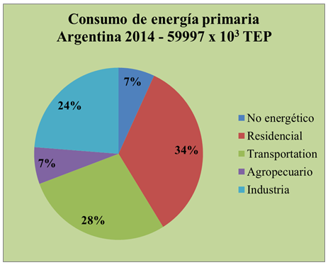 | Figure 1. Energy consumption by sector in Argentina 2014. (Secretary of Energy. 2016) |
This energy is used to operate buildings for heating, cooling, lighting, water heating, cooking, and the operation of electrical devices.The energy used for the manufacturing of building materials is considered part of the industrial sector. According to Roaf, the 34% for building operation reaches almost 45% when the energy consumption for the manufacturing of building materials is added [2]. The consumption of fossil fuels is leading us towards global climate change and if we continue with this level of consumption, we will have to design differently or work and live with the consequences [3].It is necessary to develop architectural projects that include energy efficient designs and it is essential that architects, builders, contractors and homeowners understand these concepts [4].The design of buildings must take into account the local climate along with sustainable architecture principles, on both, economic and ecological aspects [5]. This will result in a lowering of costs because of the decrease in energy consumption for the construction and operation of a building. In addition, the climatically responsive building can enhance its users "sense of well-being" while it allows them to learn about and experience the use of renewable resources [6]. In buildings located in temperate continental climates where absolute humidity is lower than 15 mm of mercury, it is possible to incorporate passive solar strategies for heating in winter and for cooling in summer. Providing a sufficient quantity of thermal mass is a very important factor [7-9] and there have been several formulae developed to predict the comfortable average, maximum and minimum indoor temperatures for all seasons [10].Thermal mass is used to reduce variations in temperature inside of buildings. Thermal storage is more effective in buildings where the diurnal variation of ambient temperatures is higher than 10K [11].When implementing heat storage elements (for thermal inertia), the operations of a building are less expensive and require less energy, but the specific design according to climate must be taken into account [2, 7].Due to the day/night cycle, the presence of thermal mass can be positioned to take advantage of solar radiation by accumulating and using it during the night. If this thermal mass is located in direct sunlight, it is more effective than one that is not [12]. The orientation of thermal mass and its interior distribution are very important for this cost-effective process.In passive buildings, the conservation of energy is exploited to minimize thermal losses. In winter, there is often energy available that is greater than the daytime heating requirements from solar and internal gains during the day. Then, this energy can be stored in the materials of the building (roof, walls and ceiling) in order to be available at night.The solutions provided in summer by popular architecture in desert and semi-desert places (with absolute humidity lower than 15 mmmHg), has been to “take advantage of the great temperature variation during the day-night cycle, delaying the penetration of heat as far as possible so that it reaches the interior at night, when it is least bothersome…” [14].In Argentina, there is an extensive area of arid climate that requires the presence of thermal mass in buildings. Figure 2 shows several dry climates that are called: arid mountain, arid hill, arid steppe and arid Patagonia. These climates are characterized by high temperature ranges with low temperatures in the winter and high temperatures in the summer, as well as low relative humidity and high clearness which allows for many sunny and partly cloudy days throughout the year. | Figure 2. Climatic zones of Argentina |
Figure 3 shows the isolines of thermal amplitude for the entire region of Argentina during January (Summer in the Southern Hemisphere). It can be observed that much of the territory possesses high thermal amplitude values in correspondence with arid climates. In these cases, the presence of thermal mass is very desirable for solar energy storage in the winter and it is important to know where direct solar radiation falls within a building in order to use appropriate materials that can receive and store this energy.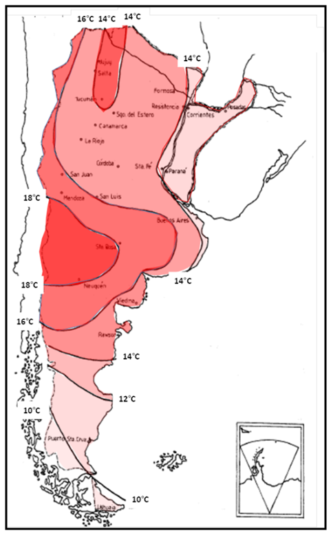 | Figure 3. Isolines of thermal amplitude in January (Summer) of Argentina [13] |
In the summer, this thermal mass acts as a deposit of energy that refreshes interior spaces. Building masonry and solid roofs can allow the structure to remain cool during summer days when interior spaces and building elements are coupled with materials for cooling by ambient heat sinks (air, sky, earth, water) and by natural means of heat transfer. These strategies reduce air conditioning requirements. It is possible to achieve temperature differences between the mean indoor and outdoor temperatures, which is greater than 10K and an indoor temperature swing of 2.5K [6].Thermal mass produces indoor temperatures between or near comfort ranges and produces a sense of shelter for occupants with a minimum consumption of energy and costs.In this context, and due to the fact that energy storage is a decisive factor for the use of renewable energy, it is imperative to advance the efficiency and presence of thermal mass along with its positioning inside buildings as alternatives to reduce reliance on HVAC in arid climates of Argentina.The specific objectives of this work are:a. To analyze the efficiency of different alternatives of interior distribution of thermal mass through a developed methodology. This paper employs the principle of observing the building during the day as seen from the trajectory of the Sun. b. To review the materials used as thermal mass along with their design characteristics to find and recommend the necessary thickness, orientation, and positioning of thermal mass elements involved for energy efficiency in passive systems.
2. Location of Thermal Mass Elements
For heating a passive building, there are three types of interior thermal storage areas:1- Primary thermal storage areas that need to be located under direct solar radiation, usually between 9 A.M. and 3 P.M. (the solar time) where in winter, nearly 82% of the daily solar radiation is transmitted through the windows. 2- Secondary thermal storage areas that are not in the sunlit area but are thermally coupled with the primary radiation storage. 3- A remote thermal storage surface area that is not in radiative contact with primary or secondary thermal storages. Heat transfer to remote storage is by convection heat transfer only.Balcomb indicates that the surfaces of insolated thermal mass have higher temperatures than other surfaces within the building [12]. Figure 4a shows an infrared thermography of direct gains within a room. It can be seen that the illuminated surface with direct solar radiation registers at almost 6K higher than the shadowed surfaces.As the solar radiation is transmitted through the window, some of it is absorbed in various surfaces within the room, and the energy is redistributed throughout the space by both infrared radiation and by air convection. This redistribution of energy is so effective that all surfaces enclosed within a direct gain space are nearly the same temperature at night (see Fig. 4b). It is important to understand that for high surface temperatures, accumulated energy penetrates into the thermal mass, and this increased energy will be released after sundown.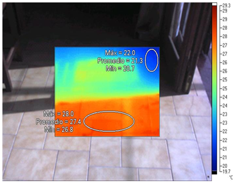 | Figure 4a. Thermography of the floor of a building with direct gain as a passive solar system: a) the maximum and minimum temperatures of the sunlit and shadowed areas at solar noon are indicated |
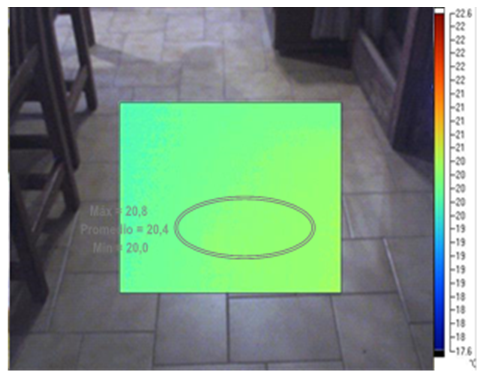 | Figure 4b. The Temperature of same ceramic floor of Fig. 4a is shown 3h after sunset |
An estimate of the storage can be obtained by assuming that the area directly heated by the sun is equal to the glazed area and then by treating all the other mass in the building as indirect storage [12, 15]. In order to estimate direct solar radiation on surfaces, a methodology is presented below that demonstrates how much sunlight will reach each interior surface element (floor, east, west and south wall) enclosed within the indoor environment in a parallelepiped shape building.This method is based on the representation of the building´s perspective as seen from the sun at every hour of the day, taking into account the size of the window and its relative location within the wall.The surfaces of the direct gain system in the facade that potentially collect solar energy can be represented with a grid of points. This grid is used to calculate direct solar beams passing through the window points and to know which element will collect the energy: floor, east wall, west wall or south wall. In figure 5, it is possible to see the elements (floor or walls) that receive direct solar energy at each hour.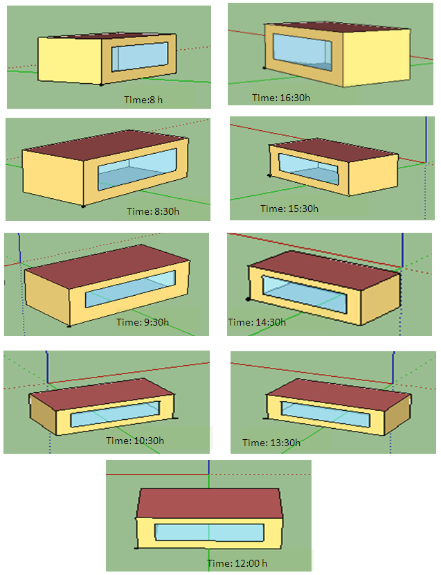 | Figure 5. A building as seen by the sun at different hours of the day |
Figure 5 shows images of a building with a window towards the Equator as seen from the sun hour by hour for June 21th (Winter in the Southern Hemisphere) from 8am to 4:30pm and it is possible to see the elements (floor or walls) that receive direct solar energy at each hour too.
2.1. Methodology
The methodology includes the following steps:1. The determination of the position of the Sun2. The determination of the coordinates of the element façades (windows, etc.) as seen from the Sun at every hour.3. The determination of the corresponding surfaces of the interior elements that are under sunlight at each hour1- Determination of the position of the SunThe position of the Sun is determined by two angles: altitude  and azimuth
  (Fig.6). Solar altitude can be obtained by equation (1) and the solar azimuth by the group of equations (2) [16].
 | (1) |
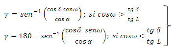 | (2) |
Where: = solar altitude (°)
 = solar azimuth (°)L = latitude of place (South of the Ecuador, negative)
 = solar declination (°)
 = Hour angle, the angular displacement of the sun, East or West of the local meridian due to rotation of the earth on its axis (15° per hour); morning negative, afternoon positive.2. Determination of the coordinates of the building elements as seen by the Sun at every hour.
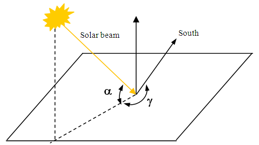 | Figure 6. Angles that define the position of the Sun: solar altitude (α), solar azimuth (γ) |
A point in space is represented in Cartesian coordinates in three dimensions x, y and z. A point as seen from the Sun can be represented by coordinates in two dimensions (Figure 7). Expressions that obtain xi and yi, coordinates of the point seen from the Sun, are calculated using equations 3 and 4, deducted from Figure 7. 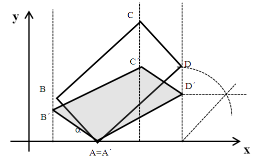 | Figure 7. ABCD are corners of building as seen in plant view; A´B´C´D´ are corners of building as seen from the sun. [17] |
Points ABCD correspond to the vertices of the building seen in plant view, which are transferred to positions A´B´C´D´, when they are seen from the Sun, when the solar azimuth is γ and the solar altitude is α.The mathematical expressions that calculate the coordinates of point D, for example, as seen from the sun are equation (3) and equation (4).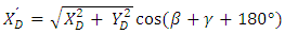 | (3) |
 | (4) |
Where:  XD, YD, ZD coordinates of point D in the spaceXD´, YD´ coordinates of point D as seen from the sunA subroutine has been developed that computes the values of the points indicated for this calculation, which changes hour-by-hour for any given day. Similarly, the boundary points of the window can be calculated along with all the points of the interior walls of a space. This creates a grid, composed of a quantity of determined points in each in a row (horizontal sense) and of a specific number of columns (vertical sense). The number of points in each row is obtained according to step, the distance between points. Usually 10 points/m are taken in each direction to obtain sufficient accuracy.It is possible to quantify all the points of the grid where each solar beam passes through and reaches the floor and the walls. In this way, the quantity of incident beams over these elements is proportional to the parts of the window through which the direct solar radiation enters. Then, it is possible know the position of the surface that is heated by the sun. In order to know which element of the interior space receives more direct solar radiation, one space with a width of 8 m, a depth of 4 m and a height of 2.6 m is studied. Both the depths and the heights are near the minimum dimensions for the rooms. Each window that faces the Equator has different measurements depending on the case. 14 cases were studied for this investigation. Table 1 shows the results of the subroutine for Case 1, as an example, for June 21, from sunrise to sunset in the city of Mendoza, Argentina.
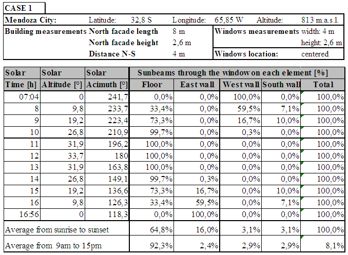 | Table 1. Result for case 1. Windows and Building characteristics, and windows surface distribution hourly |
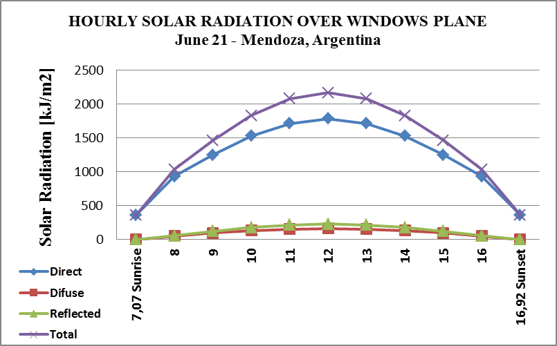 | Figure 8. Solar radiation on windows plane: direct, diffuse, reflected and total radiation |
Table 2 shows Case 1, June 21st. The window distributes direct solar radiation over different interior surface elements (in percentages of windows surface) and reaches the thermal mass storage on different walls and floors. Time intervals are considered in two ways: at every hour from 9am to 3pm and from sunrise to sunset. Figure 9 shows average hourly solar energy (Direct, Diffuse and Reflected) for June 21st for Mendoza, Argentina. It is possible to see that from 9am to 3pm are the more energetics hours of the day.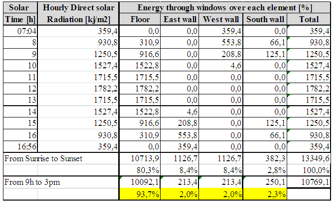 | Table 2. Result for case 1. Direct solar radiation distribution in interior elements of space |
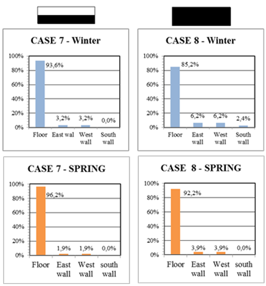
The results of direct incident solar radiation on each element are shown in figure 9a to figure 9g. The percentages of direct solar radiation through the window surface for winter (June 21st) and for intermediate seasons (September 21st) are calculated by taking into account the different solar altitudes and solar azimuths. In each case a schema indicates the facade N represented with white color and the location of the window represented with black colour.From fig. 9a to 9g, the following can be seen:1- Direct solar radiation strikes the floor in a relevant way in all analyzed cases, which also increases in intensity for all cases in the spring.2- When the window is centered in the facade, the direct solar radiation through the window that falls on the floor varies between 80% and 100%, depending on the closeness of the window to the floor. See Figures 9c and 9d.3- When the window’s length is equal to the length of the wall, the percentage of the window that transmits directly on the floor varies from 70% to 90% depending on the closeness of the window to the floor. (See Figures 9a and 9b.4- When the window is to one side of the façade facing the Equator, the wall perpendicular to the window corresponding to that side receives either 8% or 13% of the direct solar radiation from the window in spring and in winter, respectively. See Figures 9e and 9f.5- When the window is located close to the ceiling, the south wall receives direct sunlight, especially in the winter. However, the percentage is low, near 10%, depending on the depth of the room and the height of the windows. Also, when the window in this condition approaches the side of the house, percentage decreases to 2%. See Figure 9a (Case 2) and Figure 9c (Case 6). Taking all cases into account, the floor receives direct solar energy at the highest percentage, usually 70% or more of the window’s surface during the day, from 9 am to 3 pm (solar time). If the depth of the room is greater, this percentage increases. This draws our attention to the quality and quantity of the thermal mass that we should distribute within the house.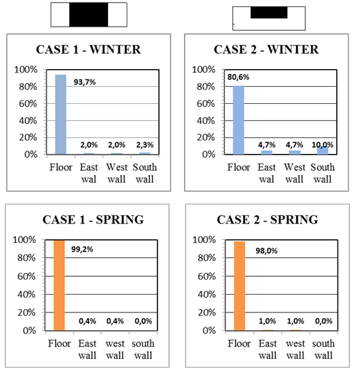 | Figure 9a. Results for Case 1 and 2 for winter and spring. A scheme is included indicated N façade (white color) and windows position (black color) |
 | Figure 9b. Results for Case 3 and 4 |
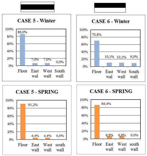 | Figure 9c. Results for Case 6 and 7 |
 | Figure 9d. Results for Case 7 and 8 |
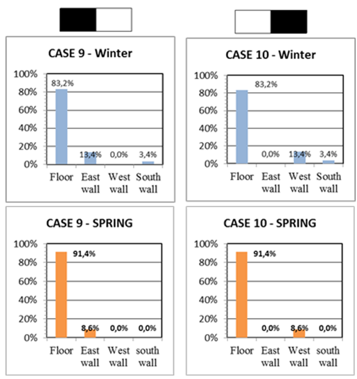 | Figure 9e. Results for Case 9 and 10 |
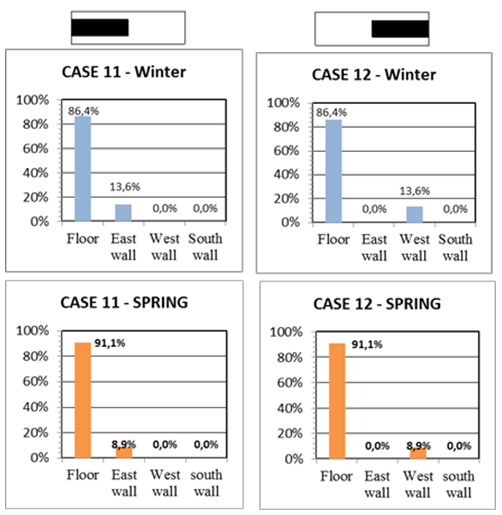 | Figure 9f. Results for Case 11 and 12 |
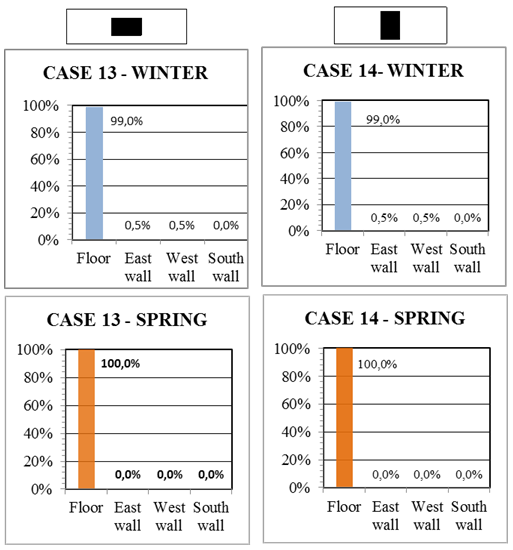 | Figure 9g. Results for Case 13 and 14 |
3. Thermal Storage Materials
Energy storage in buildings may be achieved through sensible heat of a solid or liquid medium or by latent heat materials. Sensible heat is normally stored through a change in temperature while latent heat is stored in materials without a radical a change of temperature but through phase change.Sensible heat materials have a storage capacity that depends on density and thermal conductivity. Table 3 shows the most common materials used as sensible heat storage: concrete, solid bricks, adobe, stone and water (when it is sealed for use).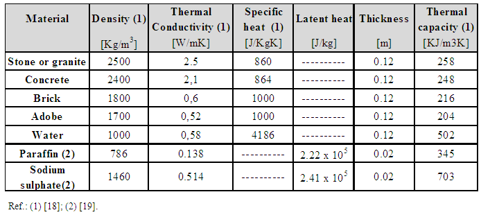 | Table 3. Thermal properties of materials used for sensible heat storage |
Total heat capacity (thc) is the amount of total heat per unit of surface which can be stored or delivered through certain materials of a given thickness. It can be calculated with Equation 5. | (5) |
Where:thc = total heat capacity (kJ/m2)c = specific heat of the material (J/kg.°C)m = mass of the element (kg) = density of the material (kg/m3)e = thickness of element (m)dT = change in the temperature of all material (°C)The specific heat of a material is the necessary heat that needs to be added to a unit of mass to raise its temperature by 1K. The heat storage capacity of ordinary building materials and water (between freezing point and boiling point) is practically independent of temperature.Thermal heat capacity of ordinary building materials is mainly dependent on the density of the material (Table 2). The means of accumulation requires high thermal conductivity in order to allow very quick heat transfer from an outside surface to an internal storage. In addition, high density and high conductivity are good indicators for sensible heat transfer.The thickness of the walls and floors define the mass available for storage. The effective thickness of ordinary building materials is between 80 mm and 160 mm for a period of charge and discharge of 24 hours, when the heat is supplied on one side only [20]. Roaf indicates that (effective) thickness may be reduced to 100 mm without significantly reducing performance [2].Water has a very large storage capacity per unit of volume and may be used in thicker storage layers. Water produces a very practical isothermal storage as a result of its natural flow circulation.(PCM) phase change materials promise a great release of energy through melting and/or solidification. The amount of stored heat can be expressed with equation (6):
 | (6) |
Where:thc = thermal heat storage (kJ/m2)c = specific heat of the material (J/kg.°C)m = mass of the element (kg) = density of the material (kg/m3)e = thickness of element (m)Tf = temperature of melting point (°C)
 T1 = (Tf-T1) = difference between initial and melting point temperature of PCM (°C).
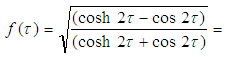
 T2 = (T2-Tf) = difference between melting point temperature of PCM and final temperature (°C).Phase Change Materials (PCM) have advantages when compared with other materials especially if the storage temperature is above the melting point. Benard have shown that the advantage of paraffin walls over concrete walls is that they are lighter (including containers) at about one-tenth of the weight of a concrete wall, they allow for average useful efficiency, sustain average comfort conditions and demonstrate an average daily storage similar to those of a concrete wall [21]. This is an enormous advantage for recycled building materials because it becomes possible to incorporate thin thermal panels.The problem with paraffin wax is that it has low thermal conductivity (see Table 3). Ansone analyze the amount of accumulated heat in containers made from a recycled material that encapsulated a PCM material and they utilize small containers that can provide a large heat transfer area [22].In Table 3, it is possible to see the thermal capacity of solid materials at similar thicknesses as well as the thermal capacity of an equivalent volume of water at 0,12 m3 (0.12 m of thickness/m2 of surface). In the same table, PCM materials show a thermal capacity for 0.02m3 of volume and it is possible to see, for example, that 0.12 m thickness of concrete is similar to 0.014 m thickness of paraffin in terms of thermal capacity. PCM are expensive and in the extensive arid zones of Argentina, it is difficult to implement their use. There is a tendency to use organic fats of animal origin, like economic compounds to produce PCM as well [23].Thermal heat capacity (thc) is a good indicator of the quantity of energy that is possible for storage in all materials; but, for solid materials, it is not possible to store all the heat to reach the thermal capacity of the wall or floor in a day.Balcomb indicates that the figure of merit is the diurnal heat capacity - dhc [12]. This is the amount of heat that a material accumulates in a day (when its surface is subjected to higher temperatures or to solar energy), which is then discharged at night (when its surface temperature decreases).Diurnal heat capacity, dhc, is a property based on the thermal conductivity, the density and the specific heat of a material. The dhc is equivalent to the thermal admittance.Values of dhc vary according to the thickness of the material. Logically, it is best to have the largest dhc for a wall. The thicker the wall, the larger the dhc depending on material. See equations 7 to 10:
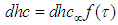 | (7) |
Where: 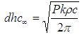 | (8) |
 | (9) |
 | (10) |
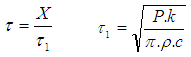
Where:dhcoo = diurnal heat capacity of storage material of infinite thickness.P = period - 24 hk = thermal conductivity of storage material [W/m.K]c = specific heat of storage material [J/kg.°C] = density of the storage material [kg/m3]
 = dimensionless thickness X = variable thickness of heat storage material [m]If the material is located under direct solar radiation for several hours per day, then the increase of surface temperature will easily exceed the room temperature (see Figure 4a).When the sun heats the air in a room and then this heat is delivered to the wall or floor by way of convection, then the possibilities of heat accumulation in that element decrease since the same air provides additional thermal resistance.Table 4 shows dhc for several storage materials of the elements used heat storage as a function of thickness when they are radiatively coupled. Table 5 indicates dhc for different materials that are convectively coupled through a heat transfer coefficient between the air in the room and a wall surface equal to 8,5 W/m2.°C. The highlighted numbers in both tables correspond to the thicknesses giving the maximum value of dhc.The dhc of interior partition walls can be determined from Table 4 and 5 by using half of the actual wall thickness because both surfaces are considered as storing energy. The result comes from an increase in the effectiveness of the wall since the surface area is doubled, compared to the same wall used on the envelope of a building. For example, a 0.20 m thick brick wall is a common construction in many parts of Argentina. If it is used as a partition wall between two rooms with direct gain passive systems in each, there will be a dhc=185 kJ/m2.°C corresponding to a wall of 0.10 m for each surface, which adds dhc=370 kJ/m2.°C to the total wall. Now, if the same wall forms part of the envelope of the building, there will be a dhc=215.5 kJ/m2.°C.
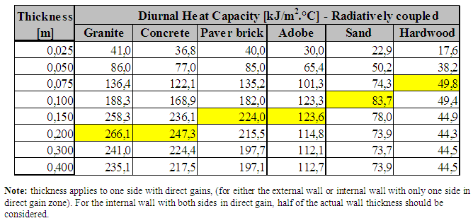 | Table 4. dhc of materials for storage heat radiatively coupled |
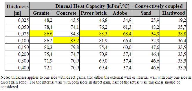 | Table 5. dhc of materials for storage heat convectively coupled |
Another interesting example is a one-inch thick wood floor, which is very commonly used for warmth. It has the dhc of approximately 10% (dhc = 17,6 kJ/m2.°C) of a concrete floor or cement base (dhc = 168,9 kJ/m2.°C for 0,10 m thickness). This is an important concept to take into account for places with scarce fuel or with limited sources of energy.In the summer, direct storage does not occur because all windows of the building are shaded. There is only indirect storage. Givoni indicates that the dhc for indirect accumulation is 40% of the value of the dhc calculated for direct accumulation [24]. Balcomb indicates a variable percentage depending on the thickness of the material [12]. This is consistent with the values shown in Table 5.During the summer, thermal mass is an excellent strategy for decreasing expected maximum temperatures [25]. The thermal mass should be distributed as evenly as possible within the building and combined with shading and night-time ventilation strategies.In the summer, air ventilation enhances convective heat losses from mass elements to lower air temperatures at night. Ceiling fans can also be used to increase indoor air movement and raise the convective heat transfer in order to generate higher comfort temperatures. The recommended rate of ventilation at night is 90 m3/h.m2 of the floor area [11].By combining both effects, the daily sunlight and thickness to improve efficiency, we can conclude that floor should be the optimal thickness indicated in Table 4, while the walls of remote thermal mass should be projected with materials whose thickness is indicated in Table 5.
4. Conclusions
Building projects with thermal storage materials is highly recommended, especially in arid or semiarid climates. By evaluating the position and amount of thermal storage materials, one can increase the thermal efficiency of the building. The amount of energy storage strongly depends on the position, material and thickness. Thermal mass is very important for winter insolation. In terms of position, the floor appears as the element most relevant for storing heat on sunny and partially cloudy days. This research concludes that 70% to 90% of the direct daily solar radiation that is transmitted by vertical direct gains impacts the floor during the more energetic hours (from 9am to 3pm – solar time). Eastern or western facades receive only 0% to 13% depending on how close the windows are to the equatorial façades. The South wall receives up to 10% of daily direct solar radiation depending on the depth of the room and the height of the windows. Also, when the window is located to one side of the equatorial façade, the percentage decreases by 2%.Optimal thickness of storage materials is studied through the diurnal heat capacity (dhc), which is dependent on the material and solar conditions. If it is sunny, optimal thickness and dhc are: 0.20 m and 266.1 kJ/m2.°C for granite; 0,20 and 247.3 kJ/m2.°C for concrete; 0,15 m and 224 kJ/m2.°C for paver brick and 0,075 m and 49.8 kJ/m2.°C for hardwood. Taking into account that 0,025 m of thickness is usual for wood floor, in this case, dhc is only 17,6 kJ/m2.°C, which means 7% dhc of a solid concrete floor, therefore is not recommended.During the summer or in remote areas in winter, the accumulation of heat in solid elements occurs without sunlight and is available in convectively coupled storage. In this case, the more appropriate thickness also depends on the material. The optimum thickness and dhc result: 0.075 m and 86.6 kJ/m2.°C for granite; 0.1 m and 85.2 kJ/m2.°C for concrete. If the material is brick, adobe or hardwood, the optimum thickness is 0.075 m with an accumulation of 83.3 kJ/m2.°C, 68.4 kJ/m2.°C and 38.8 kJ/m2.°C respectively.Therefore, those spaces with direct gain should use a thickness of 0.20 for granite or cement flooring. For brick or adobe walls, the use of 0.15 m thickness is recommended. Wood is not recommended given its low accumulation of heat. In those remote areas that do not receive direct sunlight the thickness of walls could reduced to 0,075 m especially when it comes to materials such as brick and adobe. The thickness of concrete walls could slightly increase (0.10 m) for these conditions.In construction, most walls are built with the same thickness for simplicity; however, if the findings of this research are employed, buildings will improve their thermal capacity and reduce costs through the reduction of thickness in thermal mass materials.
References
| [1] | Secretaría de Energía 2016. Balances Energéticos Nacionales – Argentina. Consultation: 09-10-2016. http://energia3.mecon.gov.ar/contenidos/verpagina.php?idpagina=3366. |
| [2] | Roaf Susan, Fuentes Manuel, Thomas Stephanie. 2003. Ecohouse 2 - A Design Guide. Architectural Press, Amsterdam. |
| [3] | IPCC. 2011. Renewable Energy and Climate Change. Cambridge University Press, Cambridge, United Kingdom and New York, NY, USA. |
| [4] | Milne M., Liggett R., Benson A., Bhattacharya Y. 2009. Climate Consultant 4.0 Develops Design Guidelines for Each Unique Climate. www.aud.ucla.edu/energydesign-tools. |
| [5] | Wassouf M. 2014. De La Casa Pasiva Al Estándar Passivhaus. Ed. Gustavo Gili. Barcelona. |
| [6] | Esteves A. 2013. Arquitectura sustentable: desarrollo y evaluación de factores que relacionan el diseño arquitectonico con el desempeño ambiental y económico del edificio en climas templado-continentales. Ph Tesis. FAUD. Universidad de Mendoza. Argentina. |
| [7] | Givoni B. 1992. Comfort, climate analysis and building design guidelines. Energy and Buildings, 18, pp. 11-23. |
| [8] | Esteves A., Gelardi D., Ganem C., Mercado M.V. 2004. Eficiencia económica de la masa térmica en el acondicionamiento térmico de climas templados. Avances en Energías Renovables y Medio Ambiente Vol. 8, Nº 1. http://www.asades.org.ar/averma.php. |
| [9] | Henze G.P., Pfafferott J., Herkel S., Felsmann C. 2007. Impact of adaptive comfort criteria and heat waves on optimal building thermal mass control. Energy and Buildings 39, pp. 221–235. |
| [10] | Singh M.K., Mahapatra S., Atreya S.K., Givoni B., 2010. Thermal monitoring and indoor temperatura modeling in vernacular buildings of North-East India. Energy and Builcing 42, pp. 1610-1618. |
| [11] | Balaras C.A. 1996. The role of thermal mass on the cooling load of buildings. An overview of computational methods. Energy and Building 24, pp. 1-10. Elsevier. |
| [12] | Balcomb J.D., Barley C.D., Mc Farland R.D., Perry J.E. Jr., Wray W.O. and Noll S. 1983. Passive Solar Design Handbook, Volume Three. DOE/CS0127/2. Washington. U.S.Department of Energy. |
| [13] | IRAM 11603. 1996. Acondicionamiento Térmico de Edificios. Clasificación Bioambiental de la República Argentina. Instituto Argentino de Normalización. ICS 91.120.10. |
| [14] | Coch H. 1998. Chapter 4 – Bioclimatism in vernacular architecture in Architecture, Comfort and Energy. Ed. Gallo, C., Sala M., Sayigh A.M.M. Elsevier. Amsterdam. |
| [15] | Flores Larsen S., Lesino G. 2001. Modelo térmico del programa SIMEDIF de simulación de edificios. Rev. Energías Renovables y Medio Ambiente. Vol. 9, pp. 15 – 24. |
| [16] | Kreither J., Kreith F. (1979). Solar Energy Handbook. Ed. Mc. Graw Hill. NY. |
| [17] | Los S. 1986. Solar perspective: a graphic technique to draw building as seen by the sun. Passive Solar Conf. ISES, pp. 422-425. |
| [18] | Gelardi, D.; Esteves, A.; Puliafito, E.; Quero, J.; Inzirillo, R. 2000. “Bioclimatic Building with water wall solar system with bottles of polythylene Terephthalate (pet.). 3rd International Conference for Teachers of Architecture, Oxford. |
| [19] | Sharma A., Tyagi V.V., Chen C.R., Buddhi D. 2009. Review on thermal energy storage with phase change materials and applications. Renewable and Sustainable Energy Review 13, pp. 318-345. |
| [20] | Goulding et al, 1994. Energy in Architecture". The Energy Research Group. School of Architecture.University of Dublin, IRL. |
| [21] | Benard C., Body Y., Zanoli A. 1985. "Experimental Comparation of Latent and Sensible Heat Thermal Walls". Solar Energy vol. 34, N° 6, pp. 475-487. Pergamon. |
| [22] | Ansone A., Dzikevics M., Zandeckis A. 2016. Energy accumulation using encapsulated phase change materials with recycled material components. Energy Procedia 95, pp. 153-158. |
| [23] | Vilte M., Bouciguez A. 2008. Determinación experimental y numérica de propiedades termicas de grasas orgánicas. Averma. Secc. 03, pp. 47-54. Salta. |
| [24] | Givoni, B. 1994. Passive and Low Energy Cooling of Buildings. Nueva York, NY: John Wiley. & Sons. |
| [25] | Singh M.K., Mahapatra S., Atreya S.K., Givoni B. 2010. Thermal monitoring and indoor temperatura modeling in vernacular buildings of North-East India. Energy and Buildings 42, pp. 1610-1618. |

 Abstract
 Reference
 Full-Text PDF
 Full-text HTML