-
Paper Information
- Paper Submission
-
Journal Information
- About This Journal
- Editorial Board
- Current Issue
- Archive
- Author Guidelines
- Contact Us
Architecture Research
p-ISSN: 2168-507X e-ISSN: 2168-5088
2016; 6(3): 57-67
doi:10.5923/j.arch.20160603.02

ConvNet Use in Architectural Design Process: Evaluation System of the Artificial Creativity Couple
 Abstract
 Reference
 Full-Text PDF
 Full-text HTML
Joaquim Silvestre1, Yasushi Ikeda1, François Guéna1, 2
1Faculty of Media and Governance, Keio SFC, Fujisawa, Japan
2MAP-MAACC, ENSAPLV, Paris, France
Correspondence to: Joaquim Silvestre, Faculty of Media and Governance, Keio SFC, Fujisawa, Japan.
| Email: |  |
Copyright © 2016 Scientific & Academic Publishing. All Rights Reserved.
This work is licensed under the Creative Commons Attribution International License (CC BY).
http://creativecommons.org/licenses/by/4.0/

The use of algorithms in the architectural design process can be driven by interrelated motivations including reducing labour in the representation phase and gaining fast visual feedback. Kostas Terzidis coined the term ‘algorithmic design’ in his book Algorithmic Architecture. Based on the interaction loop between human and computer unveiled in his book, this paper proposes to apply the concept to a specific kind of algorithmic tool: convolutional neural networks (ConvNet). Some types of ConvNet can be used with deconvolution operations to produce realistic images with only a few inputs. The paper will present an evaluation system to compare digital tools that can be used in the design process. This system focuses on the couple of User and Tool in creative design issue. From these evaluations, insight on the typology of tools for designer are discussed. Then, the specificity of ConvNet based tools considered amongst other conventional tools will be presented.
Keywords: ConvNet, Design process, Algorithmic design, Architecturology
Cite this paper: Joaquim Silvestre, Yasushi Ikeda, François Guéna, ConvNet Use in Architectural Design Process: Evaluation System of the Artificial Creativity Couple, Architecture Research, Vol. 6 No. 3, 2016, pp. 57-67. doi: 10.5923/j.arch.20160603.02.
Article Outline
1. Introduction
- Design processes that involve the use of computer tools are described by Kostas in [1] as a loop of interaction seeking solution to a design problem. But this simple description covers a deeper reality that involves intentions, expressions, expectation, and understanding of how the tool works. As in human interaction, there are conventions and common ground that need to be grasped by the actors in order to qualify the interaction as a communication relationship. Since this relation presents the unique aspects of communicating with an unconscious entity, the user does not test or expect understanding from his digital interlocutor but he still has some expectation regarding obedience to his instructions. Individuals are always prone to interpret stimuli they receive on the basis of their expectation. Outside the design approach, the user expects only compliance to these commands. As long as these commands stay simple and direct, the user is aware of their nature and has a precise expectation of the output.Digital tools exist in various forms. All these forms belong to categories of functions. Usually, evaluation of these tools consists in the comparison between tools that perform the same functions. For example, benchmarking systems estimate the speed or the precision of tools of the same category.Digital tools for design are diverse and this diversity makes the insertion of a common ground for comparison a difficult task. The extension of this diversity to ConvNet based tools illuminates the need for a comprehensive classification and the evaluation of interaction types during design processes which involves digital tools. As with all tools, their purpose is to enhance human capacity. Therefore, the ensemble of tools set up for a design can be seen as enhancing various design practice such as workflow, labour time, precision or creative discovery.
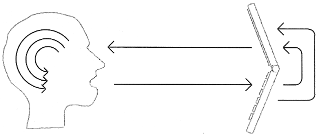 | Figure 1. Loop of interaction with a computer during design process. According to [1] “[…]design signifies not only the vague, intangible, or ambiguous, but also the strive to capture the elusive”. Based on Greek etymological research of the word “design”, Kostas concludes that collaboration with computer tools should aim to capture more efficiently the elusive thing that “we had once but we lost”. Figure from [4] |
2. The Digital Design Process
2.1. Digital Tool Interaction with an Unconscious Entity
- In the book Algorithmic Architecture, Kostas Terzidis proposes that we consider the computer as a partner in the design process. Beyond the philosophical consequence of this proposition, two ideas deserve to be studied in depth:The implication of considering an unconscious computer entity as a communication partner.The polymorphic aspect of the computer as a tool-partner for design.
2.1.1. Computer as Partner
- Since computer as partner envisions that this control loop feedback interaction is an interactive process between two entities, we propose to study this interaction as information transmission. Therefore this paper carries out such study with an information theory background. According to this theory, information is a selection from a collection of signs. From a more phenomenological point of view (figure 2), designer’s expressive power is limited because of its knowledge of the communication system. This knowledge is the supposed boundaries of the sign collection. Above that, depending on the quality of its understanding of the tool, designer projects expectations on the effect of its input. It is through an interweaving of its understanding of the tool and intentions that designer make a selection of elements in the collection to create input message. Then, through the filter of its expectation designer judge the output produced by the tool. Based on this feedback the designer and its design project gradually evolve. Progressively, understanding of a tool is reinforced through experience. Indeed, its next intention is driven by the feedback of its immediately previous interaction.
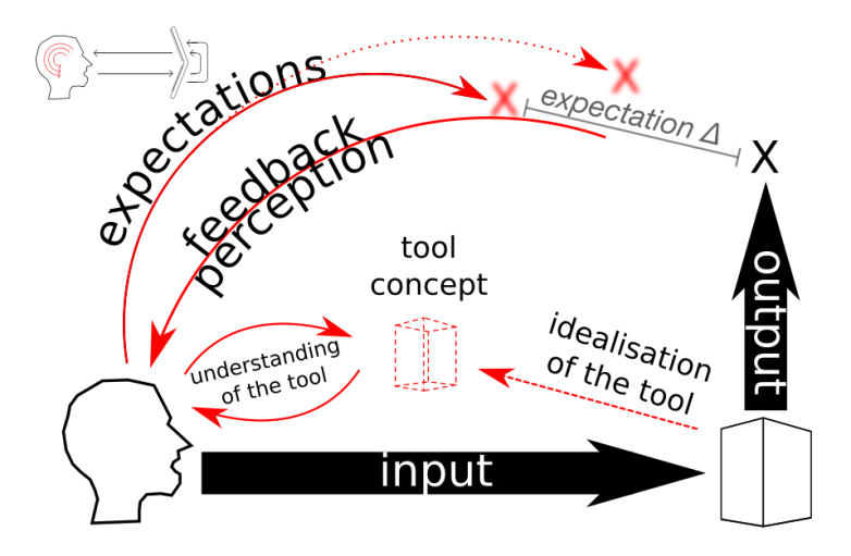 | Figure 2. Detail of the mind side in the loop of interaction with a computer during design process (figure 1). Course of thought in the user’s mind (red) when the input message is produced and when the output message is processed |
2.1.2. Computer as Tool
- The term “computer as tool” hides a more complex reality of interconnected tools: hardware, software, libraries, scripts and also input/output devices. Users interact with all of them at the same time. The interactions are generally a control loop feed back, but to propose an evaluation system it is not possible to encompass all the collections of sub-tools already available in a computer behind the same term. In Algorithmic Architecture, the implied tool is the general concept of computation. But even if all tools in the computer are computational, they don’t necessarily require the same use of computation. Some of them are meant to solve problems scientifically, others propose a model for managing data, and still others translate from one model to another. They are designed with a specific purpose and are already in a fixed form. Users encounter and discover tools as new individuals and their interactions are driven by the user’s understanding of the tool’s individuation as it's defined by Simondon in [5]. If we take a tool like GIMP or Photoshop, it is in fact an integrated group of tools that work together as a common environment. We cannot consider the software as a single tool. The single tool use is based on the pace of 'activation unit level’: one feedback triggered by one or a group of input. In the end, software such as Photoshop are toolkit that work with the same model of data management.Designers never use one digital tool directly, as they are connected through a chain of sub-programs that are invisible to them. For instance, some of them are part of the GUI (Graphic User Interface) that ease interface with the user by providing direct visual feedback, while others manage the data format to apply an algorithm efficiently.As shown in figure 3, in software development the different responsibilities are usually classified into different layers: presentation, domain knowledge and data. The presentation layer contains everything related to the GUI. The data layer concerns all the data management according to the hardware architecture.
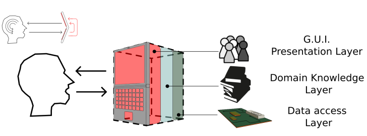 | Figure 3. Detail of the computer entity of the loop of interaction with a computer during design process (figure 1). The computer program tools are make from 3 layers. Even if the GUI layer is an important part of the tool use experience, the core functionalities of tools in software are in the Domain Knowledge layer |
2.1.3. Computer as Intelligent System
- Tools can be evaluated through various perspectives. Increase of efficiency, precision, speed, or unlocking brand new abilities are common purposes of tools. Another evaluation of tools can be focused on intrinsic qualities of the system. Like the Turing test which aims to evaluate the intelligence of a machine. In this test intelligence is reduced to the ability to have a natural conversation with a human. In fact, this test is more an evaluation of a conversational tool rather than evaluation of intelligence in all of its aspects. It assesses a limited aspect of intelligence, partly because what intelligence is has not been clearly established and is hard to reduce to a single ability. Similarly, the notion of creativity presents such challenges. Both lack of an objective formal definition, so it is not possible to make a program that emulates creativity or intelligence.The evaluation by a jury in the Turing test reflects the lack of an objective definition of intelligence; it relies on a consensus. The efficacy of the test is up to the judgement and intelligence of the jury. A less able jury may be persuaded by an unsophisticated discussion. This shows the subjective nature of the evaluation. In artificial intelligence, intelligence is mainly in the human perception that recognize intelligence. This synthetic intelligence resonates with the intelligence of the observer. With an even more lax definition, creativity follows a similar process of recognition by ‘resonance’− observers recognise somewhat creative outcome as something that they see in themselves too.As with other tools, ConvNet based design tools are evaluated by the added value they bring to the creative aspect of the design. Indeed, precision, speed or new abilities of tools in design are only meaningful in how they help to reach the goals of the designer: finding a better solution.It follows that evaluation of the creativity in the system is dependent on the perspective of the designer. They are the first person concerned, and judge at each instance of feedback if they are satisfied with the output they get. Since this is a subjective judgement, we cannot put a metric on this aspect, but by regarding the effort needed to produce the input for this tool, we can evaluate the efficiency of the system by comparing the trade off between input and output.
2.2. Nature of the Interaction: Information Processing
- The use of digital tools occurs in the digital design process as a subclass of the general design process. The use of tools usually happens during a action called in [6] conception operation. According to Architecturology, a framework theory of design process, conception operations are an attribution of a measure; deciding a level in a gradation of choice. As ‘measure’ covers a wide meaning, this could be meters as much as symbols. The measure attribution is made on a substrate model, and gradually the model changes by accumulating these “measures” until it becomes the final version of the project. Each conception operation is made upon a substrate model that receives and records gradually all operations. Conception operations are classified into various ‘scales’ that correspond to the general topic of conception operations in architecture design. An example of an Architecturologic description of a conception operation step could be: the designer aligns the windows of the second floor according to suitability to the ‘optical’ scale. They give a “measurement” of the windows' positions through a consideration of non-aligned and aligned window references. They pick the measurement that seems the more suitable relatively to their known reference.Digital tools, therefore, are used to apply, or to decide, that attribution of measure in a digital format. The digital tools serve to perform the conception operation as shown in figure 4. Operations, in CAD software, are applied on a substrate model. Then, as output, a model enriched by a single assignment of measurement is created. The next conception operation accrues on that same model. Conception operations that are digitally processed are those moments when the digital interaction loop (figure 1) takes place. To characterise it within an information theory framework: tools receive information input. Information is a selection in a collection, and this selection is, in figure 4, the substrate model and digital operation input data. It may be enriched by a selection of other signs that can be options, parameters or settings of the digital tool. The substrate model can be understood as a preselection of signs that have been gathered through the previous conception operation step. As an output, the designers receive a new model. They will interpret it through the expectation that guided their selection for the input.
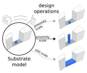 | Figure 4. Interaction with digital tools help to make a conception operation that change the substrate model into other plausible model. Those models are the result of the suit of operations in different scales |
3. Domain Knowledge Learning through a Neural Net
- Except tools based on ConvNet, digital tools are fully programmed by developers or designers. The domain knowledge is transformed into an operative form through the intellectual work of programming. By following some programming language grammar and using digital tool such as a compiler, an output of executable code is produced. This output becomes a new tool that can process a certain type of data format and produce an output that can be an analysis, a modification of the input data or even generation of new data. For instance, if we take the case of a digital tool that draws stairs based on only three parameters: the run, the rise and the starting point. A digital tool able to draw this staircase needs other parameters such as pitch line, tread depth or rise height. The knowledge for calculating these parameters is necessary to draw the staircase. In order to find them, the internal logic of the domain knowledge layer is encoded laboriously by human beings, i.e. programmers. Programmers decide what kind of input can be accepted and according to their technical knowledge of stairs design rules, they design an algorithm that translates those inputs into a stair schema. The final users don’t know and don’t need to know what happens in the domain knowledge tier. They just need to know how to use the tool to get a solution. Programs are human operative knowledge solidified to executable code.
3.1. Machine Learning with ConvNet
- Tools based on ConvNet presented in this paper are not built in the same way as usual digital tools. A part of the domain knowledge layer is not programmed manually by a conscious human being (figure 3) but learnt from very large databases through a training process. This learning system is an architecture of various layers of digital neurons called Deep Neural Network or ConvNet as explained in [7]. Each neuron has weight and a bias variable that are randomly assigned before the training. During a training sessions, each training instance submits an image and its corresponding label. The values of each pixel of the image are processed through the network and depending on the value of the weight and bias of the neurons at the other side of the network, one answer among many is selected. Here we have a very clear illustration of information definition: a selection in a collection. Since the collection of outputs from ConvNet is limited by the number of neurons on the output layer, the system is only able to select one answer from the collection of all labels used during the training phase.If the bias and weights are randomly set, it is likely to be unreliable information which becomes the output. Training sets contain ground truth labels in order to compare this unreliable output with the correct one. The back propagation algorithm will back propagate the correct answer through the network by changing weight and bias. Those changes are made in order to get the correct answer if the image is resubmitted later. The parameters of the neurons are not any more randomly set. Gradually, after thousands of automatised training sessions with different sets of pictures and correct labelling, the network starts to structure itself to select the correct label within the set of labels. In the end of the process the system ability to select the correct label is extended to images that had not been used in training. The system described here is for image recognition but, by using a similar principle, speech recognition and textual analysis can be performed. The methodology of training for prediction is powerful and can be extended to the same types of operations as those done by human-designed algorithms. As an example, even if past algorithms were more efficient, neural networks can be trained to predict trigonometric relationships between the angles of a triangle, or to perform multiplication.
 | Figure 5. Example of a Basic ConvNet taken from neuralnetworksanddeeplearning.com. The output layer contain the possible results |
3.2. Deconvolution
- Researchers in ConvNet wanted to know more about how information is encoded in the ConvNet after training. To do so, they used the network backwards in order to make it produce images. Deep Dream [9] was originally created to show what kind of features are encoded in the ConvNet. Elements of the initial input picture that stimulate feature detectors are modified in order to increase that stimulation response. The produced image is resubmitted until a number of iterations set by the user were reached. Currently, several other programs use deconvolution of trained ConvNet to generate images, e.g. Neural Style [11] and DCGAN [9]. The key element in those programs is the trained neural network used as a domain knowledge layer.The types of deconvolution process which use ConvNet are examined as tools in this paper. They are not specifically designed as a tool for designers, but designers who find usefulness of these tools in their design process can integrate them in their toolbox. They will be described through their interaction aspect because this is necessary in order to understand them as a process that modifies the data and the designer's mind at the same time.
3.2.1. Deep Dream
- The inputs are made up of one image and two parameters: an initial picture to initiate the dream, the neuron layer the user wants to stimulate, and the number of iterations. As said before, a trained ConvNet used as domain knowledge layer is a key element of those deconvolution system. In Deep Dream [10], since it uses the ConvNet features to modify the initial image, changing the ConvNet changes the image generation. Because it’s a component of the tool, changing the ConvNet should not be considered as an input parameter. The most important input parameter is the input image. Before submitting this image to Deep Dream, alteration of this image with other digital tools like in Figure 6 can effectively orient the modification of the output image.
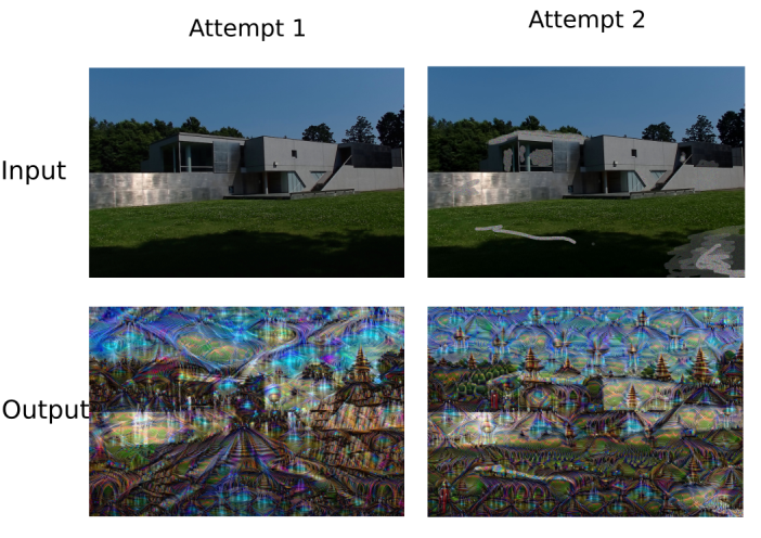 | Figure 6. DeepDream tool utilisation. Editing the input image with raster graphic tool allow to influence the 'dream' of the system |
3.2.2. Neural Style
- Regarding the previous one, this program has a more structured input system. Indeed, a simple grammar based expression is illustrated through this program: two images are submitted. The operator connecting the two operand images is “apply the style of picture A on picture B”. By using this, users progressively explore the meaning of “style”: a pattern of texture that is used to represent things. Hence such programs work quite well with impressionist paintings but not very well with cartoons. Indeed, impressionists are well known for their use of textures to represent things in their painting while cartoons are more using lines and flat colour surface. Without textures pattern to detect, Neural Style program doesn’t produce visually meaningful outputs.The purpose of this software can be shifted for architecture design goals: designers can use it as a tool to apply texture automatically to roughly designated areas. In this case the understanding of the tool behaviour is clearer than Deep Dream and user expectation about creativity of the tool narrows down to an intelligent system that fulfils automatically the proper application of textures on suitable areas of the picture. As shown in figure 7, with a vague indication of the texture application, the system apply them and complete the details.
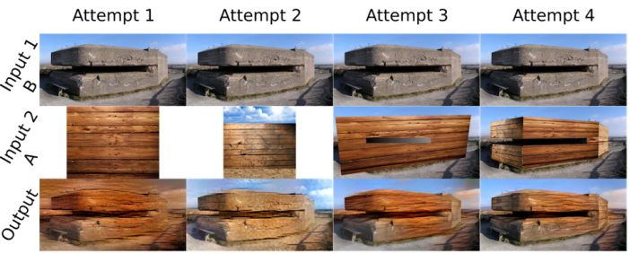 | Figure 7. Modification of the style input image (A) is the main variable of Expressivity in the Neural Style tool |
4. Evaluation Methodology
- Inspired by the methodologies of metadesigners as in [12], a tetrahedral evaluation chart can take into consideration all the possible relations between the agent and other entities involved in the utilisation of digital tools for Design. This diagrammatic concept allows a systematic and comprehensive approach of these 4 elements: • Input message• Output message• Tool• User
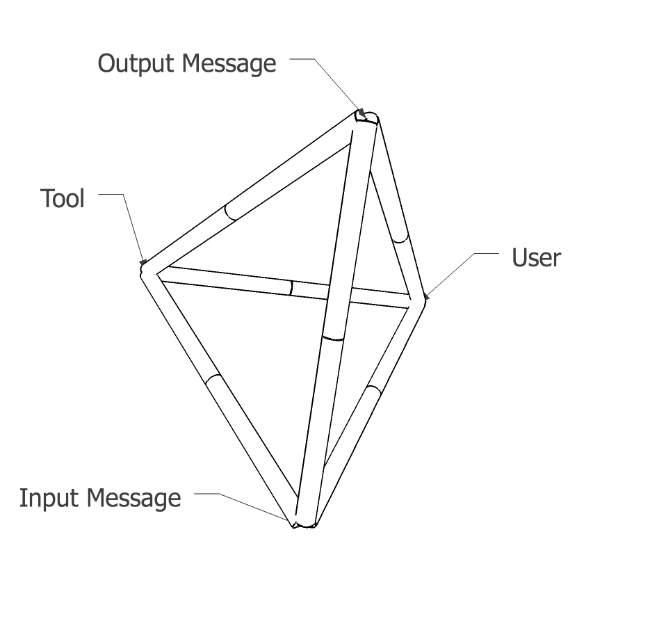 | Figure 8. Diagrammatic representation of the relations involved in digital tool utilisation. Each face represent an Orthogonal View: a specific approach to envision the relations and their interactions |
|

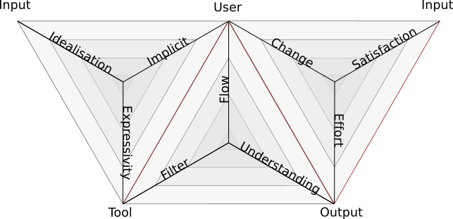 | Figure 9. An unfolded version of the Tetrahedral diagram centered on User perception. This chart contain all the criteria used for the evaluation. The center of each triangle shows the lowest value of each criteria |
5. Evaluation Criteria
- The Methodology presented above is based on relationship categories that help to deconstruct the general relationship that lies between User and digital Tool. Each relationship type is judged through a criterion. How to use these criteria to rank the four tools presented in figure 10 is explained in this part.
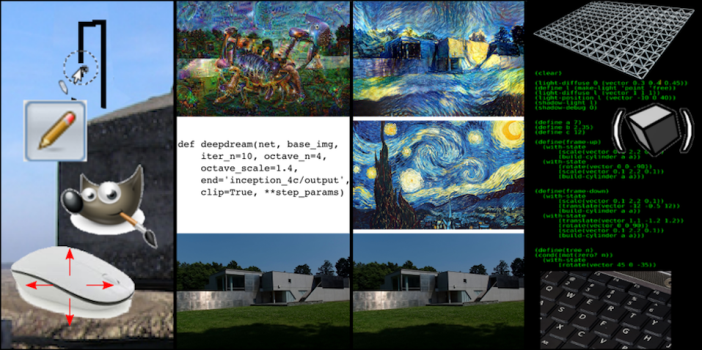 | Figure 10. Input and output of the 4 digital tools evaluated by the user: The pen tool in GIMP, DeepDream, Neural Style and Fluxus as programming language |
5.1. Production Orthogonal View
- This Orthogonal View is about the ability to produce meaningful input messages between User and Tool. Three criteria are interrelated to judge the production of the input message: Expressivity, Conceptualisation, Implicitness.
5.1.1. User to Input: Expressivity
- Expressivity between User and Input is the quality of input message that can be processed by the tool. This quality depends of the size and the diversity of the collection from which the User makes their selection to create an input message. To increase expressivity, the collection of the input message structure can be organised through the articulation of sub-selections done within sub-collection.To rank the Expressivity of the tools, the evaluator compares the ability that User has to convey their intention through the input message. Tools with a basic expressivity have a small collection and a simple input message structure. On the other hand, tools with high expressivity can process complex input messages that offer more options to transpose User's intention.
5.1.2. Input to Tool: Implicitness
- Implicitness between Input and Tool is the type and quantity of information that do not need to be inserted in the input message. Usually that information is about the User’s context during the Tool utilisation. Nonetheless, they can be about the hardware context of execution, the physical world or any context where the tool utilisation can take place.To rank Implicitness of the tools, evaluator compare the implicit information in the input message. If this implicit information is solely about the most basic condition of digital tool use context, this is the degree-zero of Implicitness. Meanwhile, if the Tool manages enough implicit information from the reality of the User's context, the Implicitness is rated as richer.
5.1.3. User to Tool: Conceptualisation
- Conceptualisation is the creation of a personal Tool Concept that narrates how it works. The tool purpose and reaction are anticipated by the User through this Tool Concept. As soon as the tool is encountered, based on preconceptions, the tool becomes a Tool Concept that is placed in the User’s mental collection of abilities. The User evolves toward its design project through conception operation, assuming those abilities are available (see 2.2).To rank Conceptualisation, the evaluator compare the clarity of its Tool Concept. If the designer can make correct predictions of the tool behaviour and output, the relation between User and Tool reaches a level of assimilation. Otherwise, the Tool Concept is still vague and may be assimilated with more experience or study later.
5.2. Feedback Orthogonal View
- The Feedback Orthogonal View (FOV) is the phase that happens right after the POV. This phase is about processing the output message as a feedback from the tool in the communication process. How the output message is perceived, has been analysed through three criteria: Filter, Understanding and Flow.
5.2.1. User to Output: Filter
- The Filter between User and Output is the way to assimilate the output of the tool. This filter is constructed by an imaginative process based on the expectations that emerge during the input message construction. Indeed, from the intention expressed in the message, and the Tool Concept, the User imagines a range of possible output message. This category of possible output message becomes intuitively a chart to interpret the effective output message.To rank Filter of the User to Output relation, evaluator compares the openness of User’s expectation regarding the input message produced and its Tool Concept. If the expected result is precisely defined, the Filter is ranked as locked. Otherwise, if the User’s expectation belongs to a large range of possibilities or a category definition, the filter criterion is open.
5.2.2. User to Output: Understanding
- The Understanding between the User and the Output is the potential to make evolve the Tool Concept through the feedback received during the use experience. This potential is measured as a rate of learning from feedback.To rank Understanding in the User to Output relation, evaluator compares the evolution of User’s Tool Concept in regard to the feedback received. If its Tool Concept doesn’t evolve with the tool feedback, the Understanding rate is low. Otherwise understanding rate is high when at each feedback the User feels improvement of the Tool Concept.
5.2.3. Tool to Output: Flow
- The Flow between the Tool and the Output is the criterion to evaluate the pace of interaction. The interaction back and forth time line starts with input message production then output generation concluded by the feedback assimilation.The input message production duration is up to the User but can present incompressible duration due to the production process. Output generation lasts from the moment the input message has been sent to the moment the feedback arrives. This duration is up to the quality of the algorithm implementation during the tool development. Finally, feedback assimilation is a process that doesn’t have precise ending because it’s completely up to the User’s mind. The Flow evaluate the average duration and balance between those 3 durations.To rank Flow of the Tool to Output relation, evaluator compares the duration input message construction and output generation. If it is relevant, user can include in the comparison the length of the feedback assimilation. Long input construction and output generation tools have a slow Flow pace. Real-time tools with instant tool input production have a rapid Flow pace.
5.3. User Process Integration Orthogonal View
- This Orthogonal View concern the relation between Input and Output in the User point of view. The tool is excluded from the relation system because it focuses on the ratio of effort and the scale of change that give a value to the output within the design and production process of the designer. It integrates the effects of the digital tool in a tool chain. The evaluated tool is between the output of a previous tool and the input of another tool. So, the integration in a workflow and the convenience provided by the tool is seen from the User’s perspective in this Orthogonal View. Satisfaction, Scale and Effort criteria allow the evaluation of the tool integration in User design Process.
5.3.1. User to Output: Satisfaction
- The Satisfaction between User and Output is the validation by the User of the tool output as a valuable document for design. It doesn’t imply that the output document contains the expected result. The question that is assessed is: is it a creative outcome? As Artificial Intelligence reveals its value through the gaze of the observers, the artificial creativity emergence is authenticated by their witness. The recognition of creativity or the creativity triggered in the designers’s mind is the sole criterion used to judge the output. The Turing test makes the interlocutors wonder if in the other room there is a human or not. But they build their judgement on the intellectual quality of the conversation. This judgment of intelligence is based on the recognition in the output of intelligence feature similar to their own model of intelligence. Here, even if the User does not wonder if it’s a human or not who creates those images, designer evaluate if this output could be considered as a creative contribution from its digital partner in design. The evaluation runs like the tester evaluates if the interaction is a conversation of interest in the Turing test.To rank the Satisfaction of the User to Output relation, evaluator compare multiple utilisation of the tool and judge if generally the output has been useful in the diversification of User’s creativity. Note that in a productive use of the tool, the Satisfaction happens only through fulfillment of locked Filter expectation (see Figure 11).
 | Figure 11. Various relation of dependency amongst the criteria. In red we have the tool learning loop. Blue connections represent the satisfaction factor shared with the tool use for productivity. Green is the Satisfaction specific to a tool use for creative issue |
5.3.2. Input to Output: Scale
- The Scale between the Input and the Output is the amount of new data generated in the Output compare to the data provided in the Input. This criteria give an indication about the scale of change by feedback. To rank the Scale between Input and Output the evaluator compare if lots of new data are produced in the output. If like in a calculation, the output is one digit, the Scale of tool is low. Otherwise, if like in Deepdream use, most of the pixel values of the input image are changed, the tool is ranked with higher Scale of change than a mere pocket calculator.
5.3.3. User to Input: Effort
- The Effort between User and Input is the labour cost to produce the input message that generates the Output. To rank the Effort in the User to Input relation, the evaluator compares the labor for producing the input message. The comparison can be based on the duration or on the difficulty that was perceived during the input message production.
6. Analysis of the Evaluation
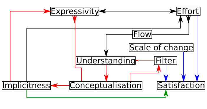
6.1. Interaction between Criteria for Tool Typology
- During the evaluation process, we figure out that criteria have interactions. These interactions are similar in different tools and illuminate the existence of a typology within the digital tool. Criteria that describe same relation in different orthogonal view tend to be inversely proportional.For example, the Effort and Expressivity present this kind of relation: if the Expressivity increase, it becomes more time consuming to produce the correct selection. It follows that Effort criteria increase with the Expressivity. But if the Effort are too demanding, there is a risk of loss in Understanding through a slower Flow and Satisfaction could be diminished too. It could be hard to select between tools that have such trade off. A rule of thumb seems to look on average biological limitation of Users in general. For instance according to [13], an average human can manage 4 entities in its short-term memory. If follows that picking tools that have input message structure that are associating 4 sub-selections seems to balance Expressivity and Effort judiciously. If we look closely on the relations between the above analysed relation, we can figure that Implicitness feature has a direct influence on 3 other criteria and specifically on the Satisfaction when the tool is used in heuristic creativity. According to the hypothesis developed in [14], the influence of Implicitness is explained by the extension of human mind to its near context. Implicit recognition of the same near context allow creative suitability of the output message. This sole quality does not make the specificity of ConvNet tools. It’s the synergies of the different relation that creates a new category of digital tool.
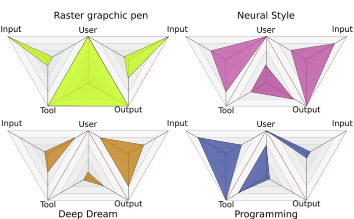 | Figure 12. Evaluation of the 4 tools. The tools presented in Figure 10 have been ranked with the different criteria of the evaluation system. The result (table 1) are reported on the unfolded tetrahedral diagram (figure 9) to get a visual comparison of the tools |
6.2. Specificity of ConvNet Based Tool
- The comparison of the tools through these criteria offers a reading grid to understand the specificity of new tools based on ConvNet. Schematically, these tools come to fill in a gap between easy and rapid input production tools and programming tools that can offer large scale of change at costly efforts.Finally, since the Satisfaction in Design process is related to serendipity, tools that present Implicit feature have probability to produce output that triggers creative satisfaction. Above that, whether the output provides high or low satisfaction if the cost to produce the input messages is low, Users can attempt to obtain creative insight for almost no Efforts.
7. Conclusions
- We can see through this evaluation system that ConvNets are efficient tools at the beginning of the architectural design process. They allow loose specification, selection in a huge alphabet and do not require much effort. From experience we know that in a later phase of the design process, creativity gives way for productivity and precision. There is a glass ceiling that prevents ConvNet from being a useful tool for this rendering phase of design process. Compared to output produced with tools specially designed for representation production, output of ConvNet based tools present too much artifact that makes them unpleasant to see. Output cannot be precise enough to specify clearly a solution or a vision. The same advantages that make them useful at the beginning phase of the design process, imprecision in the input, make them useless at the end of the process.